EP1202610A2 - Verfahren zum Ansteuern einer sensorgesteuerten Lampe - Google Patents
Verfahren zum Ansteuern einer sensorgesteuerten Lampe Download PDFInfo
- Publication number
- EP1202610A2 EP1202610A2 EP01117702A EP01117702A EP1202610A2 EP 1202610 A2 EP1202610 A2 EP 1202610A2 EP 01117702 A EP01117702 A EP 01117702A EP 01117702 A EP01117702 A EP 01117702A EP 1202610 A2 EP1202610 A2 EP 1202610A2
- Authority
- EP
- European Patent Office
- Prior art keywords
- sensor
- lamp
- sensor signal
- microprocessor
- switch
- Prior art date
- Legal status (The legal status is an assumption and is not a legal conclusion. Google has not performed a legal analysis and makes no representation as to the accuracy of the status listed.)
- Granted
Links
Images



Classifications
-
- H—ELECTRICITY
- H05—ELECTRIC TECHNIQUES NOT OTHERWISE PROVIDED FOR
- H05B—ELECTRIC HEATING; ELECTRIC LIGHT SOURCES NOT OTHERWISE PROVIDED FOR; CIRCUIT ARRANGEMENTS FOR ELECTRIC LIGHT SOURCES, IN GENERAL
- H05B47/00—Circuit arrangements for operating light sources in general, i.e. where the type of light source is not relevant
- H05B47/10—Controlling the light source
- H05B47/105—Controlling the light source in response to determined parameters
- H05B47/11—Controlling the light source in response to determined parameters by determining the brightness or colour temperature of ambient light
-
- Y—GENERAL TAGGING OF NEW TECHNOLOGICAL DEVELOPMENTS; GENERAL TAGGING OF CROSS-SECTIONAL TECHNOLOGIES SPANNING OVER SEVERAL SECTIONS OF THE IPC; TECHNICAL SUBJECTS COVERED BY FORMER USPC CROSS-REFERENCE ART COLLECTIONS [XRACs] AND DIGESTS
- Y02—TECHNOLOGIES OR APPLICATIONS FOR MITIGATION OR ADAPTATION AGAINST CLIMATE CHANGE
- Y02B—CLIMATE CHANGE MITIGATION TECHNOLOGIES RELATED TO BUILDINGS, e.g. HOUSING, HOUSE APPLIANCES OR RELATED END-USER APPLICATIONS
- Y02B20/00—Energy efficient lighting technologies, e.g. halogen lamps or gas discharge lamps
- Y02B20/40—Control techniques providing energy savings, e.g. smart controller or presence detection
Definitions
- the invention relates to a method for controlling a sensor-controlled Lamp according to the preamble of claim 1 and a Sensor-controlled lamp according to the preamble of patent claim 12.
- a fluorescent lamp is known in which the Control of a ballast for the discharge tube of the fluorescent lamp depending on the signal of a light sensor via which the incidence of light from the surroundings is detected.
- a problem with such fluorescent lamps is that the incidence of Eigenlight is overlaid with the incidence of light from the environment, so that signal detected by the light sensor can be falsified.
- This problem is reinforced by the fact that the spectrum of the discharge vessel emitted light after starting the lamp changed because of the proportion Infrared radiation immediately after starting is relatively high and after one certain start time (burn-in time) drops to a low value.
- this becomes normal Infrared light contained in daylight by the one emitted in the burn-in phase Infrared portion amplified, so that the signal detected by the sensor in the burn-in phase is significantly falsified.
- This falsification of the sensor signal can, for example, cause the fluorescent lamp to start with Reduction of the ambient light starts and then again after the start switches off because the sensors emit a signal due to the infrared component of the natural light detect that the brightness is greater than the actual brightness, so that the fluorescent lamp despite the low incidence of light from the Environment is switched off.
- the object of the invention is a method for controlling a sensor-controlled lamp and a sensor-controlled To create a lamp in which a falsification of the sensor signals due to superimposed interference signals even under unfavorable operating conditions is minimized.
- the lamp is provided with a microprocessor, over which the temporal change of the sensor signal due to the incident Light is detected. Depending on these gradients of the sensor signal can then control parameters for controlling the lamp be determined.
- This concept according to the invention makes it possible for the first time the control of the illuminant depending on the change over time to control the incidence of light so that external influences such as temperature fluctuations Type of covers, sources of interference etc., as well as the burn-in behavior recorded via the gradient and taken into account in the control becomes.
- the control over the time change of the control signal enables it, for example, the reduction of the infrared portion of the natural light to be detected extremely precisely during the burn-in phase, so that the lamp during the stoving phase - regardless of temperature, condition the lamp, the quality of the lamp, the power supply, the Type of lamp cover, mounting position, etc. - operated in one mode no change due to the incident light on the sensor the operating state of the discharge vessel.
- the normal control the lamp only takes place when the infrared portion is in natural light has subsided, so that the change in the sensor signal due to time the relatively constant incidence of light from the surroundings is low. This means, this switchover is no longer dependent on a medium-sized, usual one Operating conditions adapted dead time, but is individual, with each The fluorescent lamp is switched on depending on the operating conditions redefined so that it functions properly the lamp is guaranteed.
- the value falls below a predetermined limit value of the change over time Switch-off or switch-over threshold after each start process fixed by a predetermined value above the size of the sensor signal when the limit value is reached. That is, according to the invention these switch-off or switchover thresholds at each Starting process redetermined, so that a manual adjustment as described above State of the art is not required.
- the lamp can be switched off, for example, because then it can be assumed that there is sufficient daylight.
- Switching off can of course also on other operating conditions, such as for example a power reduction, a flashing, a dimming or similar can be switched.
- Interference signals can also be generated by external ambient light - for example car headlights, Headlights from neighboring buildings etc.- are hidden, since these stray light sources usually with a sudden increase the brightness are connected. That is, from the sudden change of the control signal is concluded on the presence of a stray light and according to the invention switched a dead time that runs until the stray light no longer influences the ambient light. That is, during this dead time the control of the discharge vessel is not changed.
- external ambient light for example car headlights, Headlights from neighboring buildings etc.- are hidden, since these stray light sources usually with a sudden increase the brightness are connected. That is, from the sudden change of the control signal is concluded on the presence of a stray light and according to the invention switched a dead time that runs until the stray light no longer influences the ambient light. That is, during this dead time the control of the discharge vessel is not changed.
- An emergency shutdown can also be specified via the microprocessor Be over which the lamp automatically when a predetermined switches off maximum sensor signals.
- the time recording of the incidence of light via the microprocessor enables it, a light curve depending on a light change cycle, for example, to capture a daily cycle, so that when known Light characteristic from the change in the sensor signal over time Conclusion on the cycle time, for example the time of day is possible.
- the lamp can then function as a function of this determined cycle time to be controlled.
- the fluorescent lamp according to the invention is preferably used with two Sensors executed, the signals of both sensors in the microprocessor processed independently or together.
- the lamp can be made particularly compact if the microprocessor, the sensors and the lamp control (pilot control unit, etc.) a single common board are included.
- the operational safety of the sensor-controlled lamp can be increased if a program for a test cycle is stored in the microprocessor, when the lamp is started up or when it is covered arbitrarily the sensors are passed through.
- the Lamp switched on and off for example after predetermined time intervals be so that the user can easily from the functionality the lamp can convince.
- FIG. 1 shows a schematic illustration of a fluorescent lamp 1.
- This has a discharge vessel 2, the end of which is fastened in a base housing 4 is.
- a screw-in base 6 for screwing in the fluorescent lamp 1 formed in a lamp holder.
- On the outer circumference of the base housing 4 are two diametrically arranged infrared sensors 8, 10 arranged, via which the infrared portion of the incident light can be detected is.
- a circuit board 12 indicated by dash-dotted lines recorded on which the two infrared sensors 8, 10, a microprocessor 14, as well as the usual lamp control, such as the ballast 16 (see Figure 2) added to control the discharge vessel 2 are.
- the Microprocessor 14 due to the time course of the sensors 8, 10 incident light to set and switch certain switching thresholds change and thus an optimal adjustment of the lamp control in Depends on the condition of the lamp, the network and the environmental conditions to ensure.
- Figure 2 shows a highly simplified circuit diagram of the circuit is recorded on the circuit board 12 indicated by dash-dotted lines. Accordingly, becomes the input signal ⁇ of the two corresponding to the incidence of light Sensors 8, 10 are acquired as a function of the measurement time and are acquired from these and stored sensor signals of the gradient d ⁇ / dt. In This then becomes dependent on these time-dependent values ⁇ and d ⁇ / dt Ballast 16 for the discharge vessel 2 controlled to their operating state to change (on / off; dim, blink etc.).
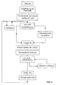
- FIG 3 shows a flow diagram of the program, which is via the microprocessor 14 is controlled.
- the program will start as soon as the Fluorescent lamp 1 is screwed into the lamp holder and a connection to the network. After such initial start-up the fluorescent lamp 1 will first be some for lamp control initialized necessary parameters, for example in memory data stored in the microprocessor 14 are read out or dependent be adjusted by the current incidence of light. This in memory of the microprocessor 14, for example Threshold values for switching the discharge vessel on and off, control times such as a self-test time, as well as maximum times for the detection of operating states (Burn-in time, dead times for blanking out interference signals etc.).
- the normal light detection takes place via the two sensors 8, 10, the sensor signals being time-dependent stored and the aforementioned gradient d ⁇ from the stored values / dt is formed.
- FIG. 4 shows the time course of the sensor signal ⁇ as a function of the time of day t.
- the sensor signal In the event of daylight, the sensor signal is at a high level, which is substantially above a switch-on threshold ⁇ E that was stored during initialization and possibly adapted to the ambient conditions.
- the sensor signal ⁇ becomes weaker and falls below the switch-on thresholds ⁇ E at time t 1 , so that the program recognizes the "dark" ambient state and generates a control signal for switching on the discharge vessel 2.
- the sensor signal ⁇ remains at an approximately constant low level and only rises again in the morning hours when the brightness falls to the threshold value ⁇ E , which it reaches at time t 2 .
- the discharge vessel 2 is switched off.
- the sensor signal ⁇ detected by the sensor when the lamp is switched off increases with increasing brightness until it reaches its maximum level in the midday.
- the lamp is started quickly and the discharge vessel 2 is switched on. If the sensor signal is still in the bright area, the incidence of light and the gradient d ⁇ / dt are recorded at predetermined time intervals and the lamp is switched on when the sensor signal ⁇ falls below the switch-on threshold ⁇ E.
- the gradient is then d ⁇ / dt the burn-in phase of the lamp in the manner described below detected and set a switch-off threshold after the burn-in phase.
- the light detection runs with the evaluation the sensor signals ⁇ and the formation of the gradients d ⁇ / dt.
- a stray light occurs when the discharge vessel 2 is switched on, can be blanked out via the program control via which the influence of the stray light can be compensated for and therefore no influence on the operating state of the discharge vessel.
- lamp 1 After exceeding the set during the program run Switch-off threshold, lamp 1 is switched off and, if necessary, from the figure 3 characteristic curve determines a time that a time-dependent program control allows. Program control then returns to yours Initial state after the initialization of the parameters and the one-off Function tests of the lamp back.
- the fluorescent lamp 2 two sensors 8, 10.
- the sensor signals ⁇ of both signals can (in Microprocessor) separately or after a weighting (average value) processed together.
- the microprocessor control according to the invention makes it possible to identify such sources of error from the gradient d ⁇ / dt and to issue corresponding correction signals to the lamp control. This will be explained with reference to the following figures 5 to 7.
- the characteristic curve shown in FIG. 4 represents an ideal state in which the sensor signal ⁇ is not falsified by interference or an inherent light component. In reality, a sensor signal arises, as shown in FIG. 5. As in the ideal state described above, the sensor signal ⁇ drops during the transition from light to dark to the switch-on threshold ⁇ E , so that the fluorescent lamp 1 is switched on when this switch-on threshold ⁇ E is reached.
- This can be predefined in the memory of the microprocessor, but in principle it is also possible to adapt this switch-on threshold dynamically depending on the characteristic curve shown in FIG. 4, so that seasonal influences, the time of initialization or the location of the lamp can be taken into account.
- the sensor signal ⁇ rises due to the comparatively high infrared portion of the natural light, so that the sensor signal moves back into the bright area.
- the infrared portion of the intrinsic light decreases, so that the sensor signal drops again below the switch-on threshold ⁇ E and, after the lamp has completely burned in, is essentially only determined by the incidence of light from the surroundings.
- the curve shown in FIG. 5 thus results in another overshoot in the bright area and a drop in the sensor signal in the dark area, the end of the burn-in phase being characterized by the transition to the approximately horizontal section of the sensor signal ,
- the burn-in phase can be reliably detected on the basis of the above-described changes in the sensor signal, the controller then reacting to the end of the burn-in phase when the gradient d ⁇ / dt falls below a predetermined limit value E 1 .
- the overshoot of the sensor signal into the bright area is disregarded, so that no control signals are emitted by the microprocessor 14 to switch off the discharge vessel to the ballast 16. The influence of natural light is thus reliably prevented during the burn-in phase.
- the program control sets a switch-off threshold ⁇ A which is a predetermined value above the sensor signal at which the burn-in phase was ended.
- the switch-off threshold ⁇ A is reset each time the discharge vessel 2 is switched on, so that the influence of sources of error, such as the outside temperature (change in the infrared light component due to fluctuations in mercury vapor pressure), fluctuations in the network or the age of the lamp are compensated for.
- the sensor signal ⁇ rises and reaches the switch-off threshold ⁇ A determined after the burn-in phase, so that the discharge vessel 2 is switched off.
- Switching off the discharge vessel 2 eliminates the comparatively small proportion of infrared light that is still present even after the burn-in phase, so that the sensor signal drops briefly downward again into the dark area and then increases with increasing brightness in the manner shown in FIG. 5 - the cycle can start again.
- the control shown in FIG. 6 differs from the control shown in FIG. 5 only in that the switch-off threshold ⁇ A determined after the burn-in phase is not kept constant as in the exemplary embodiment described above, but is changed dynamically depending on the course of the sensor signal in the dark area.
- Such dynamic tracking of the switch-off threshold ⁇ A (t) makes it possible to compensate for slow changes in the sensor signal, for example caused by temperature changes during the dark phase (in particular in winter time). This means that if the temperature drops comparatively strongly during the night, the infrared light component of the natural light is increased due to the decreasing mercury vapor pressure, so that the sensor signal rises slightly in the dark area.
- the gradient d ⁇ / dt of the sensor signal is, however, significantly lower than during the burn-in phase, so that the lamp control remains in its normal mode and does not decide whether a burn-in phase is present.
- the switch-off threshold is then changed as a function of this low gradient d ⁇ / dt in the manner shown in FIG. 5, the switch-off threshold ⁇ A always being a predetermined value above the respective sensor signal.
- To change the switch-off threshold with increasing brightness can prevent the dynamic change of the switch-off threshold to a predetermined time range of the characteristic curve shown in FIG be limited so that no dynamic tracking in the morning hours the switch-off threshold occurs.
- a stray light limit value E 2 is stored in the memory of the microprocessor 14, with which the gradient d ⁇ / dt is compared. If this gradient exceeds the stray light limit value E 2 , the program controller decides whether there is a stray light and during a certain dead time t 0 no control signal for changing the operating state of the discharge vessel 2 is emitted. After the dead time t 0 has elapsed, the gradient between the current sensor signal and the last sensor signal measured in the dark area is formed and again compared with the stray light limit value E 2 .
- the number of dead time cycles can be limited or each Dead time cycle the switch-off threshold can be increased until it reaches the level of the sensor signal resulting from the stray light exceeds ⁇ . With increasing The sensor signal superimposed by the stray light then increases in brightness continue so that the increased switch-off threshold is exceeded and the Lamp 1 is turned off in the manner described above.
- an emergency stop limit value can also be stored in the memory of the microprocessor 14 be stored by the microprocessor when it is exceeded 14 a signal for switching off the fluorescent lamp 2 is emitted. This emergency stop limit ensures that the lamp is also at a faulty program sequence when a certain brightness range is reached is switched off.
- the operational reliability of the lamp according to the invention can be further increased improve when a maximum runtime in the memory of the microprocessor 14 be stored so that, for example, after a maximum value is exceeded the burn-in time the switch-off threshold depending on the last detected sensor signal is set.
- the course of the characteristic curve can be used according to FIG. 4, a conclusion can be drawn about the time of day, whereby it can be assumed that an axis of symmetry 18 of the characteristic 4 corresponds approximately to a time from 0.00 am to 0.30 am, so that Even if the characteristic curve is recorded over 24 hours, this is a relatively precise one Determining the time is possible. Depending on this time can then additionally control the parameters described above and to be changed.
- a sensor-controlled lamp and a method for the same are disclosed Control in which the sensor signals by means of a microprocessor evaluated and based on the temporal change in the sensor signals Operating parameters of the lamp control can be changed or activated.
Landscapes
- Circuit Arrangement For Electric Light Sources In General (AREA)
- Photometry And Measurement Of Optical Pulse Characteristics (AREA)
- Lighting Device Outwards From Vehicle And Optical Signal (AREA)
Abstract
Description
- 1
- Leuchtstofflampe
- 2
- Entladungsgefäß
- 4
- Gehäuse
- 6
- Einschraubsockel
- 8
- Infrarot-Sensor
- 10
- Infrarot-Sensor
- 12
- Platine
- 14
- Mikroprozessor
- 16
- Vorschaltgerät
- 18
- Symmetrieachse
Claims (15)
- Verfahren zum Ansteuern einer sensorgesteuerten Lampe (1), bei der das einfallende Licht über einen Lichtsensor (8, 10) erfaßt wird und über eine Steuereinheit (16) in Abhängigkeit vom Sensorsignal (ε) ein Leuchtmittel der Lampe (1) angesteuert wird, gekennzeichnet durch die Schritte:Erfassen einer zeitlichen Änderung des Sensorsignals (dε/dt) undFestlegen von Steuerparametern (εE, εA, t0) zur Ansteuerung des Leuchtmittels (2) in Abhängigkeit von der Größe (ε) und der zeitlichen Änderung (dε/dt) des Sensorsignals.
- Verfahren nach Patentanspruch 1, wobei bei Unter- bzw. Überschreiten eines Grenzwerts (E1, E2) der zeitlichen Änderung des Sensorsignals (d ε/dt) der dazugehörige Sensorwert (ε) mit einem Schwellwert (εE, εA) verglichen wird und bei Unter- bzw. Überschreitung dieses Schwellwerts der Betriebszustand des Leuchtmittels geändert wird.
- Verfahren nach Patentanspruch 2, wobei nach Unterschreiten des Grenzwertes (E1) eine Ausschaltschwelle (εA) festgelegt wird, die um einen vorbestimmten Wert oberhalb der Größe des Sensorsignals (ε) bei Unterschreiten des Grenzwertes (E1) liegt.
- Verfahren nach Patentanspruch 2 oder 3, wobei bei einer nach der Festlegung des Umschaltwertes auftretenden, einen Störlichtgrenzwert (E2) überschreitenden zeitlichen Änderung des Sensorsignals (ε) während einer vorbestimmten Totzeit (t0) kein Steuersignal zur Veränderung des Betriebszustandes des Leuchtmittels abgegeben wird.
- Verfahren nach Patentanspruch 4, wobei die Totzeit (t0) verlängert wird, solange das Sensorsignal (ε) auf dem veränderten Niveau bleibt und dabei mit zunehmender Totzeit (t0) die Umschaltschwelle (εA) angehoben wird, bis das veränderte Niveau des Sensorsignals (ε) erreicht ist.
- Verfahren nach einem der vorhergehenden Patentansprüche, wobei über den Mikroprozessor (14) ein Ausschaltsignal abgegeben wird, wenn das Sensorsignal (ε) einen im Speicher des Mikroprozessors (14) abgelegten Not-Aus-Grenzwert überschreitet.
- Verfahren nach einem der vorhergehenden Patentansprüche, wobei während eines Lichtwechselzyklus, beispielsweise eines Tageszyklus erfaßte Sensorsignale (ε) im Speicher des Mikroprozessors (14) abgelegt und daraus eine Kennlinie ermittelt wird, aus der in Abhängigkeit vom erfaßten Sensorsignal (ε) ein Rückschluß auf die Zykluszeit (t) ableitbar ist.
- Verfahren nach Patentanspruch 7, wobei Abschalt-, Umschalt- oder Einschaltschwellen in Abhängigkeit von der Zykluszeit verändert oder festgelegt werden.
- Verfahren nach einem der vorhergehenden Patentansprüche, wobei die Lampe (1) Sensoren (8,10) hat und ein Mikroprozessor (14) die Sensorsignale (ε) getrennt voneinander oder beide Sensorsignale gewichtet gemeinsam verarbeitet und Steuersignale an eine Lampensteuerung des Leuchtmittels abgibt.
- Verfahren nach einem der vorhergehenden Patentansprüche, wobei bei Verbindung mit der Stromversorgung oder bei Abdecken der Sensoren (8, 10) ein Testzyklus durchfahren wird, wobei die Lampe (1) nach vorbestimmten Zeitintervallen ein- und ausgeschaltet wird.
- Verfahren nach einem der vorhergehenden Patentansprüche, wobei ein vorgegebener Einschaltwert (εE) in Abhängigkeit vom Lichteinfall bei Inbetriebnahme der Lampe (1) verändert wird.
- Sensorgesteuerte Lampe, die insbesondere nach dem Verfahren nach einem der vorhergehenden Patentansprüche ansteuerbar ist, mit zumindest einem Sensor (8, 10) zur Erfassung des einfallenden Lichtes und mit einer Steuereinheit zur Ansteuerung der Lampe (1) in Abhängigkeit vom Sensorsignal (ε), gekennzeichnet durch einen Mikroprozessor (14) zur Erfassung einer zeitlichen Änderung des Sensorsignals (dε /dt), zum Speichern der Sensorsignale und von Betriebsparametern und Grenzwerten (E1, E2) und zur Abgabe eines Steuersignals zur Veränderung eines Betriebszustandes der Lampe (1), wenn das Sensorsignals (ε) einen der Grenzwerte (εE, εA) über- oder unterschreitet.
- Sensorgesteuerte Lampe nach Patentanspruch 12, wobei zwei Sensoren (8, 10) vorgesehen sind, deren Signale von der Auswerteeinheit (14) getrennt oder gemeinsam verarbeitbar sind.
- Sensorgesteuerte Lampe nach Patentanspruch 12 oder 13, wobei auf einer gemeinsamen Platine (12) der Mikroprozessor (14) zur Erfassung, Speicherung und Verarbeitung der Sensorsignale (ε), zwei Sensoren (8, 10) und die Lampensteuerung (16) angeordnet sind.
- Sensorgesteuerte Lampe nach einem der Patentansprüche 12 bis 14, wobei die Lampe eine Leuchtstofflampe (1) ist und der Sensor (8, 10) ein IR-Sensor ist.
Applications Claiming Priority (2)
| Application Number | Priority Date | Filing Date | Title |
|---|---|---|---|
| DE10052541A DE10052541A1 (de) | 2000-10-23 | 2000-10-23 | Verfahren zum Ansteuern einer sensorgesteuerten Lampe |
| DE10052541 | 2000-10-23 |
Publications (3)
| Publication Number | Publication Date |
|---|---|
| EP1202610A2 true EP1202610A2 (de) | 2002-05-02 |
| EP1202610A3 EP1202610A3 (de) | 2004-11-17 |
| EP1202610B1 EP1202610B1 (de) | 2007-09-05 |
Family
ID=7660778
Family Applications (1)
| Application Number | Title | Priority Date | Filing Date |
|---|---|---|---|
| EP01117702A Expired - Lifetime EP1202610B1 (de) | 2000-10-23 | 2001-07-26 | Verfahren zum Ansteuern einer sensorgesteuerten Lampe |
Country Status (6)
| Country | Link |
|---|---|
| US (1) | US6580221B2 (de) |
| EP (1) | EP1202610B1 (de) |
| CN (1) | CN1275501C (de) |
| CA (1) | CA2359537C (de) |
| DE (2) | DE10052541A1 (de) |
| ZA (1) | ZA200108520B (de) |
Families Citing this family (14)
| Publication number | Priority date | Publication date | Assignee | Title |
|---|---|---|---|---|
| US7417378B2 (en) * | 2002-11-06 | 2008-08-26 | Jihn-Kuk Kim | Apparatus for controlling lighting lamp with security function and lighting control method using the same |
| DE10322987A1 (de) * | 2003-05-21 | 2004-12-09 | Patent-Treuhand-Gesellschaft für elektrische Glühlampen mbH | Lampe mit drehbarem Sockel |
| KR200334515Y1 (ko) * | 2003-08-18 | 2003-11-28 | 황윤규 | 복합 센서가 일체로 구비된 절전형 자동 점멸 램프 |
| KR100964613B1 (ko) * | 2003-09-04 | 2010-06-21 | 삼성전자주식회사 | 램프 모니터링 장치, 이를 갖는 램프 모니터링 시스템,이를 갖는 백라이트 어셈블리 및 이를 이용한 액정표시장치 |
| US7148628B2 (en) * | 2004-07-30 | 2006-12-12 | Desa Ip, Llc | Photosensitive control with dynamic calibration |
| US7372010B1 (en) * | 2004-11-12 | 2008-05-13 | Hilary Boehme | Combination socket and photosensor for measuring and adjusting intensity of lamp in the socket |
| JP4634906B2 (ja) * | 2005-10-18 | 2011-02-16 | 株式会社フジクラ | 車両用照明装置 |
| TWM396557U (en) | 2010-08-11 | 2011-01-11 | Cnl Lighting Corp | Photo-driving light with a timer |
| DE102012008215B4 (de) | 2012-04-18 | 2019-06-13 | Heribert Oechsler | Vorrichtung zur Realisierung einer Referenzuhr mit selbsttätiger Anbindung der internen Systemzeit an die Erdrotation |
| CN106018899A (zh) * | 2016-07-08 | 2016-10-12 | 华立科技股份有限公司 | 红外唤醒智能电表的处理方法 |
| DE102016220075A1 (de) * | 2016-10-14 | 2018-04-19 | Audi Ag | Kraftfahrzeug und Verfahren zur 360°-Umfelderfassung |
| CN110234190A (zh) * | 2018-03-06 | 2019-09-13 | 松下家电研究开发(杭州)有限公司 | 一种便座照明灯的控制方法 |
| WO2021081077A1 (en) * | 2019-10-21 | 2021-04-29 | Milwaukee Electric Tool Corporation | Portable lighting device with ramp-down capability |
| CN110972381B (zh) * | 2019-12-31 | 2022-03-11 | Tcl空调器(中山)有限公司 | 灯光控制方法、设备及存储介质 |
Family Cites Families (10)
| Publication number | Priority date | Publication date | Assignee | Title |
|---|---|---|---|---|
| US4996606A (en) * | 1987-11-14 | 1991-02-26 | Canon Kabushiki Kaisha | Light emitting device and original reading apparatus having the device |
| US5367223A (en) * | 1991-12-30 | 1994-11-22 | Hewlett-Packard Company | Fluoresent lamp current level controller |
| DE19514973A1 (de) * | 1995-04-24 | 1996-10-31 | Steinel Gmbh & Co Kg | Dämmerungsschalter |
| DE19514972A1 (de) | 1995-04-24 | 1996-10-31 | Steinel Gmbh & Co Kg | Dämmerungsschalter |
| DE19633159A1 (de) * | 1996-08-17 | 1998-02-19 | Abb Patent Gmbh | Verfahren zum Terminieren technischer Vorgänge und Vorrichtung zur Durchführung des Verfahrens |
| US5837994C1 (en) * | 1997-04-02 | 2001-10-16 | Gentex Corp | Control system to automatically dim vehicle head lamps |
| US6035266A (en) * | 1997-04-16 | 2000-03-07 | A.L. Air Data, Inc. | Lamp monitoring and control system and method |
| US6028396A (en) * | 1997-08-19 | 2000-02-22 | Dark To Light | Luminaire diagnostic system |
| US6188177B1 (en) * | 1998-05-20 | 2001-02-13 | Power Circuit Innovations, Inc. | Light sensing dimming control system for gas discharge lamps |
| US6483245B1 (en) * | 2000-09-08 | 2002-11-19 | Visteon Corporation | Automatic brightness control using a variable time constant filter |
-
2000
- 2000-10-23 DE DE10052541A patent/DE10052541A1/de not_active Withdrawn
-
2001
- 2001-07-26 EP EP01117702A patent/EP1202610B1/de not_active Expired - Lifetime
- 2001-07-26 DE DE50112954T patent/DE50112954D1/de not_active Expired - Lifetime
- 2001-10-17 ZA ZA200108520A patent/ZA200108520B/xx unknown
- 2001-10-19 US US10/008,122 patent/US6580221B2/en not_active Expired - Lifetime
- 2001-10-22 CA CA2359537A patent/CA2359537C/en not_active Expired - Fee Related
- 2001-10-23 CN CNB011371234A patent/CN1275501C/zh not_active Expired - Lifetime
Also Published As
| Publication number | Publication date |
|---|---|
| EP1202610B1 (de) | 2007-09-05 |
| ZA200108520B (en) | 2002-10-17 |
| DE10052541A1 (de) | 2002-04-25 |
| US20020057569A1 (en) | 2002-05-16 |
| CN1275501C (zh) | 2006-09-13 |
| US6580221B2 (en) | 2003-06-17 |
| CA2359537C (en) | 2011-03-15 |
| CN1350418A (zh) | 2002-05-22 |
| CA2359537A1 (en) | 2002-04-23 |
| DE50112954D1 (de) | 2007-10-18 |
| EP1202610A3 (de) | 2004-11-17 |
Similar Documents
| Publication | Publication Date | Title |
|---|---|---|
| EP1202610A2 (de) | Verfahren zum Ansteuern einer sensorgesteuerten Lampe | |
| DE69912750T2 (de) | Lcd-projektor | |
| EP0801880B1 (de) | Dämmerungsschalter | |
| DE60309359T2 (de) | Methode und Schaltungsanordnung zur Regelung einer LED | |
| DE19643465C2 (de) | Steuervorrichtung für einen optischen Sensor, insbesondere einen Regensensor | |
| DE102007018224A1 (de) | LED-Leuchte mit stabilisiertem Lichtstrom und stabilisierter Lichtfarbe | |
| EP2412206B1 (de) | Dimmbares betriebsgerät und beleuchtungssystem zur erhöhung der lebenserwartung bei leds und oleds | |
| EP2439451B1 (de) | Vorrichtung zur Erkennung des Vorhandenseins einer Flamme | |
| EP1745253A1 (de) | Haushaltsgerät mit innenraumbeleuchtung und beleuchtungsbaugruppe dafür | |
| EP0563696B1 (de) | Verfahren und Schaltanordnung zum Ein- und Ausschalten künstlicher Lichtquellen in einem Raum | |
| EP2310668A1 (de) | Notlichteinheit | |
| EP3518628A1 (de) | Helligkeitssensor auf led-modul | |
| EP1030540B1 (de) | Bewegungsmelder | |
| EP3420349B1 (de) | Verfahren und schaltungsanordnung zum signalisieren eines zustands eines wachstumssubstrats für eine pflanze | |
| WO1995007500A1 (de) | Verfahren und vorrichtung zur minimierung des engergieverbrauchs einer elektrischen last | |
| DE102015207331A1 (de) | Verfahren zur Adressierung von Leuchtmittelbetriebsgeräten | |
| DE102014109145B4 (de) | Computerbildschirm umfassend eine Matrixanzeigefläche und eine Statusanzeige | |
| EP2329641A1 (de) | Verfahren zur steuerung einer videoüberwachungseinrichtung | |
| DE4303808A1 (de) | Selbsttätige Beleuchtungssteuerung mit Warneinrichtung und vor Kunstlicht geschützten Detektoren | |
| DE102008053910A1 (de) | Beleuchtungsvorrichtung und Verfahren zum Betreiben einer solchen | |
| DE19514973A1 (de) | Dämmerungsschalter | |
| WO2001086243A1 (de) | Temperaturüberwachungsvorrichtung, insbesondere für schaltschränke | |
| DE102005029632B3 (de) | Bewegungsmelder mit integrierter Nachtbeleuchtung | |
| DE10361909A1 (de) | Einrichtung zur Beleuchtung einer Strichplatte einer Zieleinrichtung | |
| DE10026491A1 (de) | Lichtsensorsystem |
Legal Events
| Date | Code | Title | Description |
|---|---|---|---|
| PUAI | Public reference made under article 153(3) epc to a published international application that has entered the european phase |
Free format text: ORIGINAL CODE: 0009012 |
|
| AK | Designated contracting states |
Kind code of ref document: A2 Designated state(s): AT BE CH CY DE DK ES FI FR GB GR IE IT LI LU MC NL PT SE TR |
|
| AX | Request for extension of the european patent |
Free format text: AL;LT;LV;MK;RO;SI |
|
| PUAL | Search report despatched |
Free format text: ORIGINAL CODE: 0009013 |
|
| AK | Designated contracting states |
Kind code of ref document: A3 Designated state(s): AT BE CH CY DE DK ES FI FR GB GR IE IT LI LU MC NL PT SE TR |
|
| AX | Request for extension of the european patent |
Extension state: AL LT LV MK RO SI |
|
| 17P | Request for examination filed |
Effective date: 20041206 |
|
| AKX | Designation fees paid |
Designated state(s): BE DE FR GB IT NL |
|
| 17Q | First examination report despatched |
Effective date: 20060724 |
|
| GRAP | Despatch of communication of intention to grant a patent |
Free format text: ORIGINAL CODE: EPIDOSNIGR1 |
|
| GRAS | Grant fee paid |
Free format text: ORIGINAL CODE: EPIDOSNIGR3 |
|
| GRAA | (expected) grant |
Free format text: ORIGINAL CODE: 0009210 |
|
| AK | Designated contracting states |
Kind code of ref document: B1 Designated state(s): BE DE FR GB IT NL |
|
| REG | Reference to a national code |
Ref country code: GB Ref legal event code: FG4D Free format text: NOT ENGLISH |
|
| REF | Corresponds to: |
Ref document number: 50112954 Country of ref document: DE Date of ref document: 20071018 Kind code of ref document: P |
|
| GBT | Gb: translation of ep patent filed (gb section 77(6)(a)/1977) |
Effective date: 20071022 |
|
| ET | Fr: translation filed | ||
| PLBE | No opposition filed within time limit |
Free format text: ORIGINAL CODE: 0009261 |
|
| STAA | Information on the status of an ep patent application or granted ep patent |
Free format text: STATUS: NO OPPOSITION FILED WITHIN TIME LIMIT |
|
| 26N | No opposition filed |
Effective date: 20080606 |
|
| REG | Reference to a national code |
Ref country code: DE Ref legal event code: R081 Ref document number: 50112954 Country of ref document: DE Owner name: OSRAM GMBH, DE Free format text: FORMER OWNER: OSRAM GESELLSCHAFT MIT BESCHRAENKTER HAFTUNG, 81543 MUENCHEN, DE Effective date: 20111128 Ref country code: DE Ref legal event code: R081 Ref document number: 50112954 Country of ref document: DE Owner name: LEDVANCE GMBH, DE Free format text: FORMER OWNER: OSRAM GESELLSCHAFT MIT BESCHRAENKTER HAFTUNG, 81543 MUENCHEN, DE Effective date: 20111128 |
|
| REG | Reference to a national code |
Ref country code: DE Ref legal event code: R081 Ref document number: 50112954 Country of ref document: DE Owner name: OSRAM GMBH, DE Free format text: FORMER OWNER: OSRAM AG, 81543 MUENCHEN, DE Effective date: 20130205 Ref country code: DE Ref legal event code: R081 Ref document number: 50112954 Country of ref document: DE Owner name: LEDVANCE GMBH, DE Free format text: FORMER OWNER: OSRAM AG, 81543 MUENCHEN, DE Effective date: 20130205 |
|
| REG | Reference to a national code |
Ref country code: DE Ref legal event code: R081 Ref document number: 50112954 Country of ref document: DE Owner name: OSRAM GMBH, DE Free format text: FORMER OWNER: OSRAM GMBH, 81543 MUENCHEN, DE Effective date: 20130822 Ref country code: DE Ref legal event code: R081 Ref document number: 50112954 Country of ref document: DE Owner name: LEDVANCE GMBH, DE Free format text: FORMER OWNER: OSRAM GMBH, 81543 MUENCHEN, DE Effective date: 20130822 |
|
| PGFP | Annual fee paid to national office [announced via postgrant information from national office to epo] |
Ref country code: NL Payment date: 20130719 Year of fee payment: 13 Ref country code: BE Payment date: 20130719 Year of fee payment: 13 |
|
| PGFP | Annual fee paid to national office [announced via postgrant information from national office to epo] |
Ref country code: GB Payment date: 20130719 Year of fee payment: 13 |
|
| PGFP | Annual fee paid to national office [announced via postgrant information from national office to epo] |
Ref country code: IT Payment date: 20130729 Year of fee payment: 13 |
|
| REG | Reference to a national code |
Ref country code: NL Ref legal event code: V1 Effective date: 20150201 |
|
| GBPC | Gb: european patent ceased through non-payment of renewal fee |
Effective date: 20140726 |
|
| PG25 | Lapsed in a contracting state [announced via postgrant information from national office to epo] |
Ref country code: NL Free format text: LAPSE BECAUSE OF NON-PAYMENT OF DUE FEES Effective date: 20150201 |
|
| PG25 | Lapsed in a contracting state [announced via postgrant information from national office to epo] |
Ref country code: IT Free format text: LAPSE BECAUSE OF NON-PAYMENT OF DUE FEES Effective date: 20140726 |
|
| PG25 | Lapsed in a contracting state [announced via postgrant information from national office to epo] |
Ref country code: GB Free format text: LAPSE BECAUSE OF NON-PAYMENT OF DUE FEES Effective date: 20140726 |
|
| REG | Reference to a national code |
Ref country code: FR Ref legal event code: PLFP Year of fee payment: 16 |
|
| REG | Reference to a national code |
Ref country code: DE Ref legal event code: R081 Ref document number: 50112954 Country of ref document: DE Owner name: LEDVANCE GMBH, DE Free format text: FORMER OWNER: OSRAM GMBH, 80807 MUENCHEN, DE |
|
| REG | Reference to a national code |
Ref country code: FR Ref legal event code: PLFP Year of fee payment: 17 |
|
| PG25 | Lapsed in a contracting state [announced via postgrant information from national office to epo] |
Ref country code: BE Free format text: LAPSE BECAUSE OF NON-PAYMENT OF DUE FEES Effective date: 20140731 |
|
| REG | Reference to a national code |
Ref country code: FR Ref legal event code: CA Effective date: 20180607 Ref country code: FR Ref legal event code: CD Owner name: OSRAM GMBH, DE Effective date: 20180607 Ref country code: FR Ref legal event code: TP Owner name: OSRAM GMBH, DE Effective date: 20180607 |
|
| REG | Reference to a national code |
Ref country code: FR Ref legal event code: PLFP Year of fee payment: 18 |
|
| PGFP | Annual fee paid to national office [announced via postgrant information from national office to epo] |
Ref country code: DE Payment date: 20200928 Year of fee payment: 20 Ref country code: FR Payment date: 20200728 Year of fee payment: 20 |
|
| REG | Reference to a national code |
Ref country code: DE Ref legal event code: R071 Ref document number: 50112954 Country of ref document: DE |