EP1203172B1 - Getriebemotor - Google Patents
Getriebemotor Download PDFInfo
- Publication number
- EP1203172B1 EP1203172B1 EP00967535A EP00967535A EP1203172B1 EP 1203172 B1 EP1203172 B1 EP 1203172B1 EP 00967535 A EP00967535 A EP 00967535A EP 00967535 A EP00967535 A EP 00967535A EP 1203172 B1 EP1203172 B1 EP 1203172B1
- Authority
- EP
- European Patent Office
- Prior art keywords
- gear
- geared motor
- shaft
- housing
- area
- Prior art date
- Legal status (The legal status is an assumption and is not a legal conclusion. Google has not performed a legal analysis and makes no representation as to the accuracy of the status listed.)
- Expired - Lifetime
Links
- 230000005540 biological transmission Effects 0.000 claims description 8
- 238000004026 adhesive bonding Methods 0.000 claims 1
- 238000000034 method Methods 0.000 claims 1
- 230000002093 peripheral effect Effects 0.000 claims 1
- 238000005192 partition Methods 0.000 description 5
- 230000014616 translation Effects 0.000 description 2
- 238000013519 translation Methods 0.000 description 2
- 238000010276 construction Methods 0.000 description 1
- 239000003292 glue Substances 0.000 description 1
- 238000004519 manufacturing process Methods 0.000 description 1
- 239000000463 material Substances 0.000 description 1
- 238000005476 soldering Methods 0.000 description 1
- 238000009987 spinning Methods 0.000 description 1
- 238000003466 welding Methods 0.000 description 1
Images
Classifications
-
- F—MECHANICAL ENGINEERING; LIGHTING; HEATING; WEAPONS; BLASTING
- F16—ENGINEERING ELEMENTS AND UNITS; GENERAL MEASURES FOR PRODUCING AND MAINTAINING EFFECTIVE FUNCTIONING OF MACHINES OR INSTALLATIONS; THERMAL INSULATION IN GENERAL
- F16H—GEARING
- F16H1/00—Toothed gearings for conveying rotary motion
- F16H1/28—Toothed gearings for conveying rotary motion with gears having orbital motion
- F16H1/32—Toothed gearings for conveying rotary motion with gears having orbital motion in which the central axis of the gearing lies inside the periphery of an orbital gear
-
- H—ELECTRICITY
- H02—GENERATION; CONVERSION OR DISTRIBUTION OF ELECTRIC POWER
- H02K—DYNAMO-ELECTRIC MACHINES
- H02K7/00—Arrangements for handling mechanical energy structurally associated with dynamo-electric machines, e.g. structural association with mechanical driving motors or auxiliary dynamo-electric machines
- H02K7/10—Structural association with clutches, brakes, gears, pulleys or mechanical starters
- H02K7/116—Structural association with clutches, brakes, gears, pulleys or mechanical starters with gears
-
- F—MECHANICAL ENGINEERING; LIGHTING; HEATING; WEAPONS; BLASTING
- F16—ENGINEERING ELEMENTS AND UNITS; GENERAL MEASURES FOR PRODUCING AND MAINTAINING EFFECTIVE FUNCTIONING OF MACHINES OR INSTALLATIONS; THERMAL INSULATION IN GENERAL
- F16H—GEARING
- F16H1/00—Toothed gearings for conveying rotary motion
- F16H1/28—Toothed gearings for conveying rotary motion with gears having orbital motion
- F16H2001/2881—Toothed gearings for conveying rotary motion with gears having orbital motion comprising two axially spaced central gears, i.e. ring or sun gear, engaged by at least one common orbital gear wherein one of the central gears is forming the output
Definitions
- the invention relates to a geared motor in which the motor an electric motor and the gearbox a planetary gear is.
- the invention addresses the problem of such a problem Small volume motor, especially with a short overall length, train.
- the epicyclic gear train as an eccentric gear is a in the generic engine transmission particularly small construction volume with high translation achieved.
- the gear part of the gear motor can be easily reach a length of only about 8 mm.
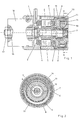
- an electric motor 3 is arranged in the between the closed end wall of the pot-shaped housing 1 and the partition 2.
- This Electric motor 3 consists of a fixedly attached to the housing Stator and one connected to a rotor shaft 4 Rotor 4.
- Rotor shaft 5 protrudes on both sides of the electric motor 3 axially out.
- the protruding from the partition 2 Part consists of a first, adjacent to the partition 2 Rotor shaft area 6 and an adjoining, axially freely tapering, second rotor shaft area 7.
- a flange is mounted as an output shaft 8.
- the shape of the Output shaft 8 is cup-shaped, with the freely running out Cylinder jacket area radially on the outside of the housing 1 supported on a rotary bearing.
- a roller bearing can be used as a rotary bearing 9 may be provided.
- the first rotor shaft region 6 runs with an axis of rotation E by a value e eccentric to the rotor shaft axis Z.
- a disc-shaped power transmission means 10 rotatably mounted on the eccentric first rotor shaft area 6 .
- This power transmission means 10 is concentric with two fitted into one another, namely an outer ring gear 11 and a radially spaced in this lying inner ring gear 12.
- the two ring gears 11 and 12 engage in associated ring gears the outer ring gear 11 in a housing-fixed ring gear 13 and the inner ring gear 12 in a fixed with the output shaft 8 connected inner ring gear 14.
- the two ring gears 13 and 14 have different ones Numbers of teeth.
- the gear ratio of the gearbox will determined by the measure of the selected eccentricity e as well the difference in the number of teeth.
- the spinning inner ring gear 14 relative to the outer ring gear fixed to the housing 13 has a larger or smaller number of teeth a different direction of rotation of the output shaft 8 before.
- the geared motor described can glue different parts together his. Glued to the adjacent parts, for example be the rotor 5 and the stator of the electric motor that Partition 2 between the electric motor and transmission area as well the ring gears 13, 14 and the inner ring gear 12. Such Bonding is just one example of a material bond Connection, also by welding, soldering or the like can be achieved.
- the rotor shaft 4 also extends through the closed end wall of the housing 1, in which it is rotatably mounted. The one over there grips outwardly projecting region 15 of the rotor shaft 4 a rotatably and displaceably attachable to the housing 1 rotary sensor interacting with the motor gear 16.
- the rotor shaft 4 is passed axially through the rotation sensor 16, thus on the protruding from the rotary sensor 16 Area on the rotation sensor 16 axially displaceable fixing closure means 17 can be provided.
- the Closure means 17 can be free together with the rotor shaft 4 rotate with respect to the rotation sensor 16.
- the rotation sensor 16 can be implemented as a resolver or encoder.
Landscapes
- Engineering & Computer Science (AREA)
- General Engineering & Computer Science (AREA)
- Mechanical Engineering (AREA)
- Power Engineering (AREA)
- Connection Of Motors, Electrical Generators, Mechanical Devices, And The Like (AREA)
- Retarders (AREA)
Description
- Fig. 1
- einen Längsschnitt durch ein Motorgetriebe,
- Fig. 2
- einen Schnitt durch den Getriebeteil des Getriebemotors nach der Linie II-II in Fig. 1.
Claims (8)
- Getriebemotor, bei demdadurch gekennzeichnet, dass die ineinander kämmenden Verzahnungsbereiche des ersten Zahnkranzes (11) mit dem ersten Hohlrad (13) und des zweiten Zahnkranzes (12) mit dem zweiten Hohlrad (14) zumindest über einen axialen Teilbereich radial ineinander liegen.der Motor ein Elektromotor (3) und das Getriebe ein Zahnradumlaufgetriebe ist,das Getriebe und der Elektromotor (3) in einem etwa zylindrischen Gehäuse (1) axial benachbart angeordnet sind,der Elektromotor (3) einen gehäusefesten Statorring mit einem in diesem um eine zentral in dem Gehäuse (1) verlaufende Achse (Z) rotierenden Rotor (5) auf einer fest mit diesem verbundenen Rotorwelle (4) als Antriebsmittel des Getriebes besitzt unddie Rotorwelle (4) mit einem axial an den Elektromotor (3) angrenzenden ersten Wellenbereich (6) und einem weiteren sich axial daran anschließenden zweiten Wellenbereich (7) in das Getriebe eingreift,der erste Wellenbereich (6) mit einer Achse (E) gegenüber der Rotorwelle (4) mit der Achse (Z) exzentrisch versetzt ausgebildet ist, wobei die Achsen (Z und E) um einen Exzentrizitätswert (e) parallel beabstandet sind,auf dem exzentrisch versetzten ersten Wellenbereich (6) ein Kraftübertragungsmittel (10) mit zwei voneinander getrennten, zentrisch zu der E-Achse verlaufenden Umfangsverzahnungen (11, 12) rotiert, die als ein erster und zweiter Zahnkranz (11 bzw. 12) ausgebildet sind,beide Zahnkränze (11,12) in zentrisch zür Z-Achse verlaufenden, verzahnten Hohlrädern kämmen, nämlich der erste Zahnkranz (11) in einem ersten Hohlrad (13) und der zweite Zahnkranz (12) in einem zweiten Hohlrad (14),eines der beiden verzahnten Hohlräder (13, 14) fest mit dem Gehäuse verbunden ist,das andere der beiden Hohlräder (13 bzw. 14) Teil der Abtriebswelle (8) des Getriebemotors ist,bei den Zahnkranz-Hohlradpaarungen (12/14) bzw. (11/13) unterschiedliche Übersetzungen vorliegen,
- Getriebemotor nach Anspruch 1
dadurch gekennzeichnet, daß die Abtriebswelle (8) einerseits an dem Motorgetriebegehäuse (1) und andererseits auf dem zweiten Wellenbereich (7) der Rotorwelle (4) gelagert ist. - Getriebemotor nach Anspruch 1 oder 2,
dadurch gekennzeichnet, daß die Abtriebswelle (8) topfförmig ausgebildet ist und mit ihrer zylindrischen Topfwand das Motorgetriebegehäuse (1), auf dem sie axial neben den Zahnrädern (11,12) in einem radial den Elektromotor (3) umfassenden Bereich drehgelagert ist, umfaßt. - Getriebemotor nach Anspruch 3,
dadurch gekennzeichnet, daß die Drehlagerung der Abtriebswelle (8) über Nadellager erfolgt. - Getriebemotor nach einem der vorhergehenden Ansprüche,
dadurch gekennzeichnet, daß Teile des Getriebemotors stoffschlüssig miteinander verbunden sind. - Getriebemotor nach Anspruch 5,
dadurch gekennzeichnet, daß die stoffschlüssige Verbindung eine Verklebung ist. - Getriebemotor nach Anspruch 5 oder 6,
dadurch gekennzeichnet, daß ein Teil der Zahnkränze (11,12) und der Hohlräder (13,14) stoffschlüssig mit Trägerteilen verbunden ist. - Getriebemotor nach einem der vorhergehenden Ansprüche,
dadurch gekennzeichnet, daß an der von dem Getriebe abgewandten Seite des Elektromotors ein Drehsensor (16) an dem Motorgetriebegehäuse drehund verschiebefest gelagert ist, wobei in dessen Inneren die Rotorwelle (4) bei aktivem Getriebemotor rotiert.
Applications Claiming Priority (3)
| Application Number | Priority Date | Filing Date | Title |
|---|---|---|---|
| DE19939608A DE19939608A1 (de) | 1999-08-20 | 1999-08-20 | Getriebemotor |
| DE19939608 | 1999-08-20 | ||
| PCT/DE2000/002838 WO2001014767A1 (de) | 1999-08-20 | 2000-08-18 | Getriebemotor |
Publications (2)
| Publication Number | Publication Date |
|---|---|
| EP1203172A1 EP1203172A1 (de) | 2002-05-08 |
| EP1203172B1 true EP1203172B1 (de) | 2002-11-06 |
Family
ID=7919096
Family Applications (1)
| Application Number | Title | Priority Date | Filing Date |
|---|---|---|---|
| EP00967535A Expired - Lifetime EP1203172B1 (de) | 1999-08-20 | 2000-08-18 | Getriebemotor |
Country Status (5)
| Country | Link |
|---|---|
| EP (1) | EP1203172B1 (de) |
| JP (1) | JP2003507685A (de) |
| DE (2) | DE19939608A1 (de) |
| ES (1) | ES2186656T3 (de) |
| WO (1) | WO2001014767A1 (de) |
Families Citing this family (2)
| Publication number | Priority date | Publication date | Assignee | Title |
|---|---|---|---|---|
| DE102004043310B4 (de) * | 2003-11-28 | 2009-08-06 | C. Rob. Hammerstein Gmbh & Co. Kg | Untersetzungsgetriebe für eine Verstellvorrichtung eines Kraftfahrzeugsitzes |
| JP2006234005A (ja) * | 2005-02-22 | 2006-09-07 | Aisin Seiki Co Ltd | モータ組込みハイポサイクロイド減速機 |
Family Cites Families (5)
| Publication number | Priority date | Publication date | Assignee | Title |
|---|---|---|---|---|
| US1563945A (en) * | 1921-07-08 | 1925-12-01 | Vincent G Apple | Electric motor |
| US2881619A (en) * | 1957-04-23 | 1959-04-14 | Richard J Fox | Coaxial control rod drive mechanism for neutronic reactors |
| DE4134553A1 (de) * | 1991-10-20 | 1992-03-05 | Bernhard Orlowski | Von einem elektromotor angetriebenes planeten-zahnradgetriebe |
| DE4422492A1 (de) * | 1993-07-19 | 1995-01-26 | Teves Gmbh Alfred | Motor mit einem Umlaufgetriebe |
| DE29515381U1 (de) * | 1995-09-26 | 1995-11-30 | Interelectric Ag | Bürstendeckel für Gleichstrommaschinen |
-
1999
- 1999-08-20 DE DE19939608A patent/DE19939608A1/de not_active Withdrawn
-
2000
- 2000-08-18 DE DE50000737T patent/DE50000737D1/de not_active Expired - Fee Related
- 2000-08-18 WO PCT/DE2000/002838 patent/WO2001014767A1/de not_active Ceased
- 2000-08-18 ES ES00967535T patent/ES2186656T3/es not_active Expired - Lifetime
- 2000-08-18 JP JP2001518608A patent/JP2003507685A/ja active Pending
- 2000-08-18 EP EP00967535A patent/EP1203172B1/de not_active Expired - Lifetime
Also Published As
| Publication number | Publication date |
|---|---|
| EP1203172A1 (de) | 2002-05-08 |
| DE50000737D1 (de) | 2002-12-12 |
| JP2003507685A (ja) | 2003-02-25 |
| ES2186656T3 (es) | 2003-05-16 |
| DE19939608A1 (de) | 2001-02-22 |
| WO2001014767A1 (de) | 2001-03-01 |
Similar Documents
| Publication | Publication Date | Title |
|---|---|---|
| DE602004003081T3 (de) | Kraftfahrzeuglenkung | |
| EP0903471B1 (de) | Vorrichtung zur verstellung der nockenwelle einer brennkraftmaschine mit innerer verbrennung | |
| CA2328426A1 (en) | Modular motorized electric wheel hub assembly for bicycles and the like | |
| DE102005018956A1 (de) | Vorrichtung zur Nockenwellenverstellung einer Brennkraftmaschine | |
| DE10013785A1 (de) | Getriebebaukasten | |
| WO2010043193A1 (de) | Antriebswellenanordnung für ein getriebe eines kraftfahrzeuges | |
| WO2009012872A1 (de) | Integrierte innenzahnradpumpeneinheit mit elektrischem motor | |
| EP1289790B1 (de) | Direkt angetriebene antriebsachse mit planeten-differential-getriebestufe | |
| EP1191254A2 (de) | Zweistufige Getriebeanordnung | |
| DE102011011012A1 (de) | Radnabenantrieb | |
| DE10004373A1 (de) | Antrieb einer Schraubenspindelpumpe | |
| DE19714528C2 (de) | Exzentergetriebe | |
| DE10130100A1 (de) | Getriebe für ein lenkbares Antriebsrad | |
| DE102019114120A1 (de) | Motoreinheit | |
| EP3306057B1 (de) | Aktuator zur verstellung von klappen für eine verbrennungskraftmaschine | |
| DE10315151A1 (de) | Vorrichtung zur relativen Winkelverstellung einer Nockenwelle gegenüber dem antreibenden Antriebsrad | |
| EP0622544B1 (de) | Verstelleinrichtung für Propellerpumpen | |
| DE19848324B4 (de) | Kupplung | |
| WO2014044277A1 (de) | Getriebeanordnung | |
| WO2025031820A1 (de) | Planetenträgeranordnung für ein plantetengetriebe und antriebseinrichtung mit einem derartigen planetengetriebe | |
| DE102007057391A1 (de) | Zahnstangen-Hilfskraftlenkung | |
| DE19939608A1 (de) | Getriebemotor | |
| DE102016119091B4 (de) | Aktuator für eine Verbrennungskraftmaschine | |
| EP0791237B1 (de) | Motorgetriebe | |
| DE102024203036B3 (de) | Getriebe, Antriebseinheit mit einem solchen Getriebe und Fahrzeug mit Antriebseinheit |
Legal Events
| Date | Code | Title | Description |
|---|---|---|---|
| PUAI | Public reference made under article 153(3) epc to a published international application that has entered the european phase |
Free format text: ORIGINAL CODE: 0009012 |
|
| 17P | Request for examination filed |
Effective date: 20011207 |
|
| AK | Designated contracting states |
Kind code of ref document: A1 Designated state(s): AT BE CH CY DE DK ES FI FR GB GR IE IT LI LU MC NL PT SE |
|
| GRAH | Despatch of communication of intention to grant a patent |
Free format text: ORIGINAL CODE: EPIDOS IGRA |
|
| GRAH | Despatch of communication of intention to grant a patent |
Free format text: ORIGINAL CODE: EPIDOS IGRA |
|
| GRAA | (expected) grant |
Free format text: ORIGINAL CODE: 0009210 |
|
| AK | Designated contracting states |
Kind code of ref document: B1 Designated state(s): DE ES FR GB IT |
|
| REG | Reference to a national code |
Ref country code: GB Ref legal event code: FG4D Free format text: NOT ENGLISH |
|
| REG | Reference to a national code |
Ref country code: IE Ref legal event code: FG4D Free format text: GERMAN |
|
| REF | Corresponds to: |
Ref document number: 50000737 Country of ref document: DE Date of ref document: 20021212 |
|
| GBT | Gb: translation of ep patent filed (gb section 77(6)(a)/1977) |
Effective date: 20021220 |
|
| REG | Reference to a national code |
Ref country code: ES Ref legal event code: FG2A Ref document number: 2186656 Country of ref document: ES Kind code of ref document: T3 |
|
| ET | Fr: translation filed | ||
| REG | Reference to a national code |
Ref country code: IE Ref legal event code: FD4D Ref document number: 1203172E Country of ref document: IE |
|
| PLBE | No opposition filed within time limit |
Free format text: ORIGINAL CODE: 0009261 |
|
| STAA | Information on the status of an ep patent application or granted ep patent |
Free format text: STATUS: NO OPPOSITION FILED WITHIN TIME LIMIT |
|
| 26N | No opposition filed |
Effective date: 20030807 |
|
| PGFP | Annual fee paid to national office [announced via postgrant information from national office to epo] |
Ref country code: ES Payment date: 20080828 Year of fee payment: 9 |
|
| PGFP | Annual fee paid to national office [announced via postgrant information from national office to epo] |
Ref country code: FR Payment date: 20080813 Year of fee payment: 9 Ref country code: IT Payment date: 20080823 Year of fee payment: 9 |
|
| PGFP | Annual fee paid to national office [announced via postgrant information from national office to epo] |
Ref country code: GB Payment date: 20080821 Year of fee payment: 9 |
|
| PGFP | Annual fee paid to national office [announced via postgrant information from national office to epo] |
Ref country code: DE Payment date: 20081029 Year of fee payment: 9 |
|
| GBPC | Gb: european patent ceased through non-payment of renewal fee |
Effective date: 20090818 |
|
| REG | Reference to a national code |
Ref country code: FR Ref legal event code: ST Effective date: 20100430 |
|
| PG25 | Lapsed in a contracting state [announced via postgrant information from national office to epo] |
Ref country code: DE Free format text: LAPSE BECAUSE OF NON-PAYMENT OF DUE FEES Effective date: 20100302 Ref country code: FR Free format text: LAPSE BECAUSE OF NON-PAYMENT OF DUE FEES Effective date: 20090831 |
|
| REG | Reference to a national code |
Ref country code: ES Ref legal event code: FD2A Effective date: 20090819 |
|
| PG25 | Lapsed in a contracting state [announced via postgrant information from national office to epo] |
Ref country code: GB Free format text: LAPSE BECAUSE OF NON-PAYMENT OF DUE FEES Effective date: 20090818 |
|
| PG25 | Lapsed in a contracting state [announced via postgrant information from national office to epo] |
Ref country code: IT Free format text: LAPSE BECAUSE OF NON-PAYMENT OF DUE FEES Effective date: 20090818 |
|
| PG25 | Lapsed in a contracting state [announced via postgrant information from national office to epo] |
Ref country code: ES Free format text: LAPSE BECAUSE OF NON-PAYMENT OF DUE FEES Effective date: 20090819 |