EP1203184B1 - Isoliermantel für elektrofilter - Google Patents
Isoliermantel für elektrofilter Download PDFInfo
- Publication number
- EP1203184B1 EP1203184B1 EP00960459A EP00960459A EP1203184B1 EP 1203184 B1 EP1203184 B1 EP 1203184B1 EP 00960459 A EP00960459 A EP 00960459A EP 00960459 A EP00960459 A EP 00960459A EP 1203184 B1 EP1203184 B1 EP 1203184B1
- Authority
- EP
- European Patent Office
- Prior art keywords
- insulating jacket
- wall
- insulating
- units
- insulation
- Prior art date
- Legal status (The legal status is an assumption and is not a legal conclusion. Google has not performed a legal analysis and makes no representation as to the accuracy of the status listed.)
- Expired - Lifetime
Links
- 239000012717 electrostatic precipitator Substances 0.000 title description 4
- 239000011810 insulating material Substances 0.000 claims abstract description 13
- 239000002184 metal Substances 0.000 claims abstract description 9
- 239000012530 fluid Substances 0.000 claims 1
- 239000000725 suspension Substances 0.000 claims 1
- 230000008646 thermal stress Effects 0.000 abstract description 3
- 238000010521 absorption reaction Methods 0.000 abstract 1
- 238000009413 insulation Methods 0.000 description 47
- 238000010438 heat treatment Methods 0.000 description 10
- 239000012774 insulation material Substances 0.000 description 10
- 230000015572 biosynthetic process Effects 0.000 description 6
- 210000002105 tongue Anatomy 0.000 description 5
- 238000009423 ventilation Methods 0.000 description 5
- 238000010276 construction Methods 0.000 description 4
- 239000007789 gas Substances 0.000 description 3
- 239000003365 glass fiber Substances 0.000 description 3
- XLYOFNOQVPJJNP-UHFFFAOYSA-N water Substances O XLYOFNOQVPJJNP-UHFFFAOYSA-N 0.000 description 3
- 239000000969 carrier Substances 0.000 description 2
- 238000005253 cladding Methods 0.000 description 2
- 230000000694 effects Effects 0.000 description 2
- 238000005516 engineering process Methods 0.000 description 2
- 239000004744 fabric Substances 0.000 description 2
- 239000011888 foil Substances 0.000 description 2
- 239000011521 glass Substances 0.000 description 2
- 238000003860 storage Methods 0.000 description 2
- 206010011469 Crying Diseases 0.000 description 1
- 239000004831 Hot glue Substances 0.000 description 1
- 230000006735 deficit Effects 0.000 description 1
- 239000011152 fibreglass Substances 0.000 description 1
- 238000009415 formwork Methods 0.000 description 1
- 229910052602 gypsum Inorganic materials 0.000 description 1
- 239000010440 gypsum Substances 0.000 description 1
- 230000001771 impaired effect Effects 0.000 description 1
- 238000009434 installation Methods 0.000 description 1
- 238000002955 isolation Methods 0.000 description 1
- 238000004519 manufacturing process Methods 0.000 description 1
- 239000000463 material Substances 0.000 description 1
- 238000000034 method Methods 0.000 description 1
- 239000002557 mineral fiber Substances 0.000 description 1
- 239000000203 mixture Substances 0.000 description 1
- 239000012811 non-conductive material Substances 0.000 description 1
- 230000000149 penetrating effect Effects 0.000 description 1
- 230000035515 penetration Effects 0.000 description 1
- 229920001296 polysiloxane Polymers 0.000 description 1
- 238000012805 post-processing Methods 0.000 description 1
- 239000005871 repellent Substances 0.000 description 1
- 229910000679 solder Inorganic materials 0.000 description 1
- 239000007787 solid Substances 0.000 description 1
- 230000007704 transition Effects 0.000 description 1
Images






Classifications
-
- B—PERFORMING OPERATIONS; TRANSPORTING
- B03—SEPARATION OF SOLID MATERIALS USING LIQUIDS OR USING PNEUMATIC TABLES OR JIGS; MAGNETIC OR ELECTROSTATIC SEPARATION OF SOLID MATERIALS FROM SOLID MATERIALS OR FLUIDS; SEPARATION BY HIGH-VOLTAGE ELECTRIC FIELDS
- B03C—MAGNETIC OR ELECTROSTATIC SEPARATION OF SOLID MATERIALS FROM SOLID MATERIALS OR FLUIDS; SEPARATION BY HIGH-VOLTAGE ELECTRIC FIELDS
- B03C3/00—Separating dispersed particles from gases or vapour, e.g. air, by electrostatic effect
- B03C3/34—Constructional details or accessories or operation thereof
- B03C3/82—Housings
- B03C3/84—Protective coatings
-
- B—PERFORMING OPERATIONS; TRANSPORTING
- B03—SEPARATION OF SOLID MATERIALS USING LIQUIDS OR USING PNEUMATIC TABLES OR JIGS; MAGNETIC OR ELECTROSTATIC SEPARATION OF SOLID MATERIALS FROM SOLID MATERIALS OR FLUIDS; SEPARATION BY HIGH-VOLTAGE ELECTRIC FIELDS
- B03C—MAGNETIC OR ELECTROSTATIC SEPARATION OF SOLID MATERIALS FROM SOLID MATERIALS OR FLUIDS; SEPARATION BY HIGH-VOLTAGE ELECTRIC FIELDS
- B03C3/00—Separating dispersed particles from gases or vapour, e.g. air, by electrostatic effect
- B03C3/34—Constructional details or accessories or operation thereof
- B03C3/66—Applications of electricity supply techniques
- B03C3/70—Applications of electricity supply techniques insulating in electric separators
-
- B—PERFORMING OPERATIONS; TRANSPORTING
- B03—SEPARATION OF SOLID MATERIALS USING LIQUIDS OR USING PNEUMATIC TABLES OR JIGS; MAGNETIC OR ELECTROSTATIC SEPARATION OF SOLID MATERIALS FROM SOLID MATERIALS OR FLUIDS; SEPARATION BY HIGH-VOLTAGE ELECTRIC FIELDS
- B03C—MAGNETIC OR ELECTROSTATIC SEPARATION OF SOLID MATERIALS FROM SOLID MATERIALS OR FLUIDS; SEPARATION BY HIGH-VOLTAGE ELECTRIC FIELDS
- B03C3/00—Separating dispersed particles from gases or vapour, e.g. air, by electrostatic effect
- B03C3/34—Constructional details or accessories or operation thereof
- B03C3/82—Housings
-
- E—FIXED CONSTRUCTIONS
- E04—BUILDING
- E04H—BUILDINGS OR LIKE STRUCTURES FOR PARTICULAR PURPOSES; SWIMMING OR SPLASH BATHS OR POOLS; MASTS; FENCING; TENTS OR CANOPIES, IN GENERAL
- E04H5/00—Buildings or groups of buildings for industrial or agricultural purposes
- E04H5/10—Buildings forming part of cooling plants
-
- F—MECHANICAL ENGINEERING; LIGHTING; HEATING; WEAPONS; BLASTING
- F16—ENGINEERING ELEMENTS AND UNITS; GENERAL MEASURES FOR PRODUCING AND MAINTAINING EFFECTIVE FUNCTIONING OF MACHINES OR INSTALLATIONS; THERMAL INSULATION IN GENERAL
- F16L—PIPES; JOINTS OR FITTINGS FOR PIPES; SUPPORTS FOR PIPES, CABLES OR PROTECTIVE TUBING; MEANS FOR THERMAL INSULATION IN GENERAL
- F16L59/00—Thermal insulation in general
Definitions
- the invention relates to an insulating jacket for walls according to the Preamble of claim 1.
- DE 33 45 966 A1 describes a holding device for elements Insulation known.
- the individual insulation elements have protruding hook elements on that for connecting two adjacent Insulation elements are screwed together.
- the insulation elements are Can be attached to straps using the hook elements.
- the fastening devices are formed in two parts, wherein one fastener to a plasterboard and the other fastener a plasterboard arranged in parallel or attached to a wall.
- the two fasteners are connected using hot-melt adhesive or by solder.
- DE 44 35 837 A1 describes a method for fastening cladding panels known.
- the cladding panels are on a substructure screwed.
- a disadvantage of these known designs is the high expenditure of time to connect two adjacent elements or to connect one Elements with one wall.
- WO 88/03 630 A1 describes insulation for a storage container known.
- the insulation consists of individual plates, which are connected by tongue and groove are attached to each other.
- the tongues and the grooves are designed in the shape of a circular arc in order to be radial in the radial direction To be able to adapt storage tanks as well as possible.
- the invention therefore has as its object a flexible and inexpensive insulation system to create that the formation of thermal bridges practically excludes and can be installed with little effort.
- This task is characterized by the characteristics of the characteristic part of the Claim 1 solved.
- the insulation according to the invention it is possible to build modular units to create that have a high inherent stability and at the same time extreme can withstand high thermal loads.
- the one to be insulated Wall is provided with a completely uniform insulation, whereby any components protruding from the wall, such as supports, as well covered by thermal insulation or the moisture-repellent metal sheet are. The risk of creating thermal bridges is minimized Substructure is not necessary.
- the units point to their Inside connector, which is designed to correspond to the carrier are so that the units in the protruding parts of the carrier let it hang. In this way, those protruding from the wall Carriers as such are virtually included in the thermal insulation.
- the assembly of the insulation sheaths is also significantly simplified, that the units can be prefabricated and to be insulated The object is then simply hooked onto the bracket via the connector Need to become. Even for hard-to-machine areas such as corners, curves, Openings or particularly protruding components can be tailor-made Solutions are offered. It is a great advantage that this work takes place in a workshop instead of under construction site conditions can be carried out, the moisture protection in the form of Sheets are installed at the same time. Because neighboring units are in one overlap certain area, it is also guaranteed at these points that the thermal insulation has no weak point. The exchange too damaged units can be carried out in an uncomplicated manner, because the unit in question can be easily replaced without that the insulation system would be impaired.
- a particularly compact embodiment of an insulating jacket has been achieved if the insulation is stabilized by an all-round cover, preferably by bumpers connected to the outer cover and Inner panels.
- the mat-like thermal insulation is therefore on the outside and the inner surface and on its side edges covered with sheet metal, making a particularly stable, insensitive and high thermal Load-bearing unit is given. Over the total area distributed and also on the joints has such a unit uniform insulation properties, regardless of whether beams or other protruding components are covered with it.
- a preferred embodiment of the invention provides that the Bumps associated with impacts are designed as smooth plates. Thus should a particularly good interlacing of neighboring units possible become. Then there are any errors in the installation of the insulation jacket obvious due to the uneven contours and can accordingly be resolved.
- a particularly advantageous arrangement of the insulating jackets is achieved if the beams have an I, U or L profile and a kind of heat compensation duct arranged between the wall and the insulating jacket are. Thanks to the profiles, the insulating sleeves are at a distance from the wall held. This creates a rear ventilation, which advantageously can be used as a heat compensation duct. The one in this Beams in the area do not impede this rear ventilation. Also here is a significant advantage when you consider that Insulation material was previously placed on the wall, so that at all no rear ventilation remained.
- the inner sheet provided as part of the all-round cover on Insulation is particularly advantageous if the inner sheet is a perforated sheet with an additional trickle protection in the form of a glass fiber mat Is provided. Especially when there are requirements for the insulating jacket with regard to sound insulation, it is recommended to use a glass cloth to be used, which prevents insulation material from coming loose.
- the carrier on the inner sheet facing Side is provided with a glass fiber cover. Since it is with the Insulating jacket according to the invention is no longer necessary, electrostatic precipitator scooters can be moved with much less effort or cranes can be used. Of these, the insulation jackets are included to hang the connectors in the brackets. So that this is easier to handle is, the carrier with glass fiber cover or another, if possible provided smooth material which prevents the connectors or which enables insulating jackets over the straps.
- the outer cover of the insulating jacket by a Sheet metal is formed, with the outer cover and insulation material using fasteners are attached together via the connector.
- fasteners are only used to a very small extent to use.
- the insulation, with which the insulation on the wall is installed.
- a preferred embodiment of the invention provides that the outer cover and the inner sheet formed as a smooth sheet and on both sides are galvanized.
- Profiling the outer cover can be done accordingly be trained, depending on what type of construction is carried out. In a roof construction, for example, corresponding drainage or Gutters should be designed to drain the water.
- a drainage of water can also be caused by a Trapezoidal sheet serves as an outer cover. Basically any shape conceivable from the outside cover, especially since the units are factory-made are manufactured and assembled.
- the smooth sheet has a profile. This serves to prevent the outer cover from crying out.
- Another advantage of the insulating jacket according to the invention is that it is possible that the insulating jacket is equipped with a heating cable is.
- the use in an electrostatic filter is intended where it is to be prevented that those released from the raw gases Cool the suspended matter and bake it on. For this reason, it is one Heating provided specifically where the bottom of the electrostatic precipitator suspended solids collect, ensures a constant high temperature.
- the invention Insulating jacket can also be factory-made with a Heating cable.
- the heating cables run inside the unit is protected from external influences.
- the heating line within the Insulation arranged in a continuous manner and through one or more layers of foils is formed separately from the outer cover.
- two previously completely separate facilities - thermal insulation and heating - combined sensibly which also saves space.
- the invention is particularly characterized in that an insulating jacket is created for walls, in particular of electrostatic filters, which is made up of units or modules. These are special flexibly manageable, since it consists of a sheet metal jacket all around edged insulation material and connections to anyway existing supports can be attached to the filter wall.
- the building units form an independent formwork, so to speak that they cover all attachments and fixtures on the wall and the formation of thermal bridges is prevented.
- the invention Insulating jackets can be assembled in the workshop, whereby at most particularly problematic areas such as openings on the construction site still need to be tailored.
- the bumps between neighboring ones Units are by tongue and groove connections or step-like interlocking training realized. This will result in unnecessary temperature losses avoided in the area of the bumps, at the same time ensuring that the strains due to high thermal stress of the insulation system can be included.
- the insulating jacket 1 shown in FIG. 1 is an insulating jacket 1 formed with smooth sheet metal, which additionally has profiles 26 on the outside, which prevent the outer cover 4 from bulging.
- the inner plate 14 is designed as a perforated plate 20 and is provided with an additional trickle protection 17, which consists of a glass cloth and is used in particular when high demands are made on the insulating jacket 1 with regard to sound insulation.
- the assembly 2 has a rectangular cross section.
- An impact 32 or 33 is provided in and against a horizontal direction 31.
- the joint 33 has a web 34 protruding against the horizontal direction 31 on the underside.
- a longitudinal groove 35 is provided above the web 34 and is delimited at the bottom by the web 34 and at the top by a projecting part of the outer cover 4.
- the two layers of the insulating material 3 are bordered in the region of the web 34 and the longitudinal groove 35 by the bumper plate 21.
- a recess 36 is provided which is open towards the underside and is delimited by a web 37 arranged above it and projecting in the horizontal direction 31. In this area, too, the two layers of the insulating material 3 are bordered by the bumper plate 21.
- the assembly 2 also has joints 32 and 33 along a vertical direction 38, which runs perpendicular to the horizontal direction 31, which are not shown in FIG. 1.
- FIG. 2 One equipped with trapezoidal structures on the outer cover 4 Insulating jacket 1 is shown in Fig. 2.
- the outer cover 4 is with trapezoidal sheets 16 equipped, causing bulging of the outer cover 4 is prevented and also a drain of the located on this Water is guaranteed.
- the insulating material 3 consists of two layers 12 and 13, these in the horizontal direction 31st are slightly offset from each other, causing the gradations result at joint 8.
- the layers 12 and 13 are simply flat glued or stapled at the factory so that the formation of the Bumps 8 is specified. This overlaps neighboring ones Units advantageously. This brings constructive advantages Assembling the building units and at the same time prevents it from neighboring units come to the formation of thermal bridges can. Otherwise, reference is made to the description of the structural unit 2 according to FIG. 1 directed.
- FIG an embodiment An insulating jacket 1 suspended in a carrier 5 is shown in FIG an embodiment in a vertical section.
- a structural unit 2 exists from the insulating material 3, which is formed in two or more layers, and the outer cover 4.
- On the inside 10 is formed as a perforated plate 20
- Inner plate 14 can be seen, which with the outer cover 4th and the bumper plates form the all-round cover.
- a connector 11 is arranged to hang it the assembly 2 to the on the wall 6 of the object to be insulated attached carrier 5 allows.
- Mounts 27 or other hooking the Fiberglass covers that facilitate structural units can be used for the carriers 5 be assigned.
- the connector 11 and the fastening means 15 one from the outside through a bore 39 screw 40 guided in the plate 2 '.
- a bolt 41 which is fixed with a nut 42 in the screw direction is.
- the latch 42 encompasses a leg 43 of the double T profile trained carrier 5.
- a stop 44 is provided, which prevents twisting the bolt 41 prevented when tightening the screw 40.
- connection of two units 2, 2 ' with a carrier 5 via a screw 40 which is a unit 2 or 2 ' Penetrating from the outside in is primarily used when the wearer 5 do not run exactly parallel to each other and thus a bracing of the Units 2, 2 'in the direction of the carrier 5 is required. Are they lying Carrier 5 exactly one above the other, so is a connection of the units 2 on the respective carrier 5 according to that shown in FIGS. 10 and 11 Attachment principle preferred.
- Fig. 4 shows a horizontal section through a further embodiment with an insulating jacket 1, the joint 8 between the two units 2 and 2 'can be seen.
- the connector 11 are the respective Units 2, 2 'suspended in the carrier 5.
- the fasteners 15 attached to the butt 8 near the overlap 22 to prevent that there are shifts here and a tight fit of the neighboring ones
- Heat compensation duct 25 forms the rear ventilation of the entire structure guaranteed.
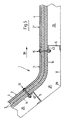
- FIG. 6 shows a further embodiment, that of FIG. 5 resembles, but in a slightly modified, folded version. Such designs can already be prefabricated in the factory or if necessary, can also be cut on site.
- FIG. 7 shows that the connection of Additional components, such as troughs 23 with the insulating jacket according to the invention 1 is easy to carry out.
- the carrier 5 is used simultaneously for the the trough 23 associated additional insulation 29 used.
- FIG. 8 Recognize embodiment A right-angled corner 28 is shown in FIG. 8 Recognize embodiment.
- two units 2 and 2 'meet which are connected via a fitting 24.
- the fitting 24 has corresponding grooves 45, 46 around the staggered Record layers 12, 13 and 12 ', 13'.
- the webs 34 and 37 grip into the grooves 45 and 46, respectively.
- unit 2 and Fitting piece 24 or unit 2 'and fitting piece 24 corresponding overlaps 22 or 22 '.
- heating lines 18 within an insulating jacket 1 are arranged.
- the heating lines 18 are covered or covered with foils 19, 19 ', 19 ".
- the insulating jacket 1 can thus be heated to a predetermined temperature.
- the Insulated jackets 1 equipped with heating lines 18 can thus advantageously are already manufactured in the factory and must be on site can only be connected accordingly.
- the assembly 2 has at its top, ie. H. against the vertical direction 38 end located on an L-shaped hook 47.
- On Leg 48 of the hook 47 is with the face 49 of the web 34 connected.
- On the side of the leg 48 facing the web 34 is in front the inner sheet 14 a profile 50 with a U-shaped direction 38 open Cross section provided that consists of a thermally non-conductive Material, especially a silicone mixture.
- a screw 51 is from the inside through a recess in the bumper plate 21 and the Leg 48 is inserted and points with its threaded end the vertical direction 38. The screw is fastened to the bumper plate 21.
- a recess 54 is provided, which is surrounded by slots running radially outwards and whose diameter is slightly smaller than the outside diameter of the Screw 51.
- the hook 47 has a second Leg 55, which is perpendicular to the other leg 48.
- In the leg 55 has a set screw 56 rotatably mounted in a thread, compared to the profile leg shown on the right in FIGS. 10 and 11 57 of the profile 50 is present.
Landscapes
- Engineering & Computer Science (AREA)
- Architecture (AREA)
- General Engineering & Computer Science (AREA)
- Civil Engineering (AREA)
- Structural Engineering (AREA)
- Mechanical Engineering (AREA)
- Building Environments (AREA)
- Organic Insulating Materials (AREA)
- Casings For Electric Apparatus (AREA)
- Sealing Battery Cases Or Jackets (AREA)
- Electrostatic Separation (AREA)
- Electrotherapy Devices (AREA)
- External Artificial Organs (AREA)
- Separation Using Semi-Permeable Membranes (AREA)
Description
- Fig. 1
- eine mit einem Glattblech versehene Baueinheit in perspektivischer Ansicht,
- Fig. 2
- eine mit Trapezblech versehene Baueinheit in perspektivischer Ansicht,
- Fig. 3
- einen Stoß zweier benachbarter Baueinheiten im Vertikalschnitt,
- Fig. 4
- einen Stoß zweier benachbarter Baueinheiten im Horizontalschnitt,
- Fig. 5
- einen abgerundeten Isoliermantel im Bereich einer abgewinkelten Wandung im Vertikalschnitt,
- Fig. 6
- einen scharfkantigen Isoliermantel im Bereich einer abgewinkelten Wandung im Vertikalschnitt,
- Fig. 7
- einen Isoliermantel mit angeschlossener Abflußrinne,
- Fig. 8
- die Ausbildung eines Isoliermantels an einer Ecke im Horizontalschnitt,
- Fig. 9
- eine Baueinheit mit darin verlaufender Heizleitung,
- Fig. 10
- einen Isoliermantel gemäß einer weiteren Ausführungsform im Vertikalschnitt und
- Fig. 11
- eine Ansicht gemäß Fig. 10 mit einem Stoß zweier benachbarter Baueinheiten.
Die Baueinheit 2 weist einen rechteckigen Querschnitt auf. In und entgegen einer Horizontal-Richtung 31 ist ein Stoß 32 bzw. 33 vorgesehen. Der Stoß 33 weist an der Unterseite eine entgegen der Horizontal-Richtung 31 vorstehenden Steg 34 auf. Oberhalb des Steges 34 ist eine Längsnut 35 vorgesehen, die nach unten durch den Steg 34 und nach oben durch einen überstehenden Teil der Außenabdeckung 4 begrenzt ist. Die zwei Lagen des Dämmstoffs 3 sind im Bereich des Stegs 34 und der Längsnut 35 von dem Stoßblech 21 eingefaßt. Am in Horizontal-Richtung 31 gelegenen Ende der Baueinheit 2 ist eine zur Unterseite hin offene Ausnehmung 36 vorgesehen, die durch einen darüber angeordneten, in Horizontal-Richtung 31 vorspringenden Steg 37 begrenzt wird. Auch in diesem Bereich sind die zwei Lagen des Dämmstoffs 3 von dem Stoßblech 21 eingefaßt. Die Baueinheit 2 weist auch entlang einer Vertikal-Richtung 38, die senkrecht zur Horizontal-Richtung 31 verläuft, Stöße 32 bzw. 33 auf, die in Fig. 1 nicht dargestellt sind.
Claims (9)
- Isoliermantel (1) für Wandungen (6), die mit flüssigen oder gasförmigen Medien hoher Temperatur in Kontakt stehen, insbesondere für Gehäuse von Elektrofiltern, bestehend aus einem Dämmstoff (3), einer vor allem gegen Feuchtigkeit absichernden Außenabdeckung (4) und Verbindern zur Fixierung an der Wandung (6), wobei Dämmstoff (3), Außenabdeckung (4) und Verbinder jeweils eine Baueinheit (2, 2') bildend ausgeführt sind, die über die Verbinder mit der Wandung (6) zugeordneten Trägern (5) koppelbar ist und die mit Stößen (8, 9) eine Überlappung (22) mit benachbarten Baueinheiten (2, 2') ergebend ausgebildet ist, dadurch gekennzeichnet, daßdie Verbinder einen L-förmigen Querschnitt zum Einhängen der Baueinheiten (2, 2') an den Trägern (5) aufweisen, undan jeder Baueinheit (2, 2') eine den Verbinder durchgreifende Schraube (51) zum Transportieren der Baueinheit (2, 2') und zum Eingreifen in eine entsprechende Ausnehmung (54) einer benachbarten Baueinheit (2, 2') vorgesehen ist.
- Isoliermantel nach Anspruch 1, dadurch gekennzeichnet, daß der Dämmstoff (3) über eine Rundumabdeckung (7) stabilisiert ist, vorzugsweise durch mit der Außenabdeckung (4) verbundene Stoßbleche (21) und Innenbleche (14).
- Isoliermantel nach einem der vorhergehenden Ansprüche, dadurch gekennzeichnet, daß die Stöße (8, 9) benachbarter Baueinheiten (2) eine Feder-/Nutverbindung ergebend ausgebildet sind.
- Isoliermantel nach einem der vorhergehenden Ansprüche, dadurch gekennzeichnet, daß die Stöße (8, 9) stufenartig ineinandergreifend ausgebildet sind.
- Isoliermantel nach einem der vorhergehenden Ansprüche, dadurch gekennzeichnet, daß der Dämmstoff (3) zweilagig ausgebildet ist, wobei beide Lagen (12, 13) leicht zueinander versetzt angeordnet sind und somit an den Stößen (8, 9) der Baueinheit (2) eine stufenartige Ausbildung ergeben.
- Isoliermantel nach einem der vorhergehenden Ansprüche, dadurch gekennzeichnet, daß der Dämmstoff (3) mindestens aus zwei Lagen (12, 13) besteht, wobei der Verbinder nur mit der der Wandung (6) zugewandten Lage (13) verbunden ist.
- Isoliermantel gemäß Anspruch 6, dadurch gekennzeichnet, daß der Verbinder am oberen Ende der der Wandung (6) zugewandten Lage (13) befestigt ist.
- Isoliermantel nach einem der vorhergehenden Ansprüche, dadurch gekennzeichnet, daß am oberen Ende der der Wandung (6) zugewandten Lage (13) die den Verbinder durchgreifende Schraube (51) befestigt ist.
- Isoliermantel nach einem der vorhergehenden Ansprüche, dadurch gekennzeichnet, daß am unteren Ende der der Wandung (6) zugewandten Lage (13) in dem Stoßblech (21) die Ausnehmung (54) vorgesehen ist.
Applications Claiming Priority (3)
| Application Number | Priority Date | Filing Date | Title |
|---|---|---|---|
| DE19938834 | 1999-08-19 | ||
| DE19938834 | 1999-08-19 | ||
| PCT/EP2000/007959 WO2001014784A1 (de) | 1999-08-19 | 2000-08-16 | Isoliermantel für elektrofilter |
Publications (2)
| Publication Number | Publication Date |
|---|---|
| EP1203184A1 EP1203184A1 (de) | 2002-05-08 |
| EP1203184B1 true EP1203184B1 (de) | 2004-03-03 |
Family
ID=7918578
Family Applications (1)
| Application Number | Title | Priority Date | Filing Date |
|---|---|---|---|
| EP00960459A Expired - Lifetime EP1203184B1 (de) | 1999-08-19 | 2000-08-16 | Isoliermantel für elektrofilter |
Country Status (6)
| Country | Link |
|---|---|
| EP (1) | EP1203184B1 (de) |
| AT (1) | ATE261084T1 (de) |
| AU (1) | AU7276000A (de) |
| DE (2) | DE50005537D1 (de) |
| DK (1) | DK1203184T3 (de) |
| WO (1) | WO2001014784A1 (de) |
Families Citing this family (1)
| Publication number | Priority date | Publication date | Assignee | Title |
|---|---|---|---|---|
| DE102006027532A1 (de) | 2005-06-24 | 2007-01-04 | Rheinhold & Mahla Ag | Flächiger Isolierkörper zur isolierenden Innenauskleidung von Räumen |
Family Cites Families (4)
| Publication number | Priority date | Publication date | Assignee | Title |
|---|---|---|---|---|
| US4152873A (en) * | 1977-09-14 | 1979-05-08 | National Gypsum Company | Bonded two piece metal stud |
| DE3345966A1 (de) * | 1983-12-20 | 1985-06-27 | Kaefer Isoliertechnik Gmbh & Co Kg, 2800 Bremen | Haltevorrichtung fuer die elemente einer daemmung |
| HUT49940A (en) * | 1986-11-04 | 1989-11-28 | Greiner Schaumstoffwerk | Insulation for tanks and mounting method for producing such insulations |
| DE4435837A1 (de) * | 1994-10-07 | 1996-04-11 | Rheinhold & Mahla Ag | Verfahren zur Befestigung von Verkleidungsplatten an einer Unterkonstruktion |
-
2000
- 2000-08-16 AT AT00960459T patent/ATE261084T1/de not_active IP Right Cessation
- 2000-08-16 DE DE50005537T patent/DE50005537D1/de not_active Expired - Lifetime
- 2000-08-16 EP EP00960459A patent/EP1203184B1/de not_active Expired - Lifetime
- 2000-08-16 DE DE10039821A patent/DE10039821A1/de not_active Withdrawn
- 2000-08-16 DK DK00960459T patent/DK1203184T3/da active
- 2000-08-16 AU AU72760/00A patent/AU7276000A/en not_active Abandoned
- 2000-08-16 WO PCT/EP2000/007959 patent/WO2001014784A1/de not_active Ceased
Also Published As
| Publication number | Publication date |
|---|---|
| DE10039821A1 (de) | 2001-02-22 |
| WO2001014784A1 (de) | 2001-03-01 |
| EP1203184A1 (de) | 2002-05-08 |
| ATE261084T1 (de) | 2004-03-15 |
| DK1203184T3 (da) | 2004-05-03 |
| AU7276000A (en) | 2001-03-19 |
| DE50005537D1 (de) | 2004-04-08 |
Similar Documents
| Publication | Publication Date | Title |
|---|---|---|
| EP2354368B1 (de) | Befestigungsbügel für Wandisolierungen | |
| EP0585663B1 (de) | Verkleidungselement für Böden, Decken und Wände | |
| EP0063733B1 (de) | Feuerschutz-Ummantelung | |
| DE69832105T3 (de) | Wand einer Gebäudefassade | |
| DE10147831B4 (de) | Ständerwand | |
| DE3435648C2 (de) | ||
| EP2722451B1 (de) | Gebäudesystem, insbesondere Wohngebäude | |
| DE3888846T2 (de) | Verbindung zwischen zwei Sandwichtafeln und Modulbausystem mit dieser Verbindung. | |
| EP3436638B1 (de) | Übergangskonstruktion zur überbrückung einer bauwerksfuge | |
| DE3327183A1 (de) | Vorrichtung zum befestigen von daemmplatten auf dachsparren | |
| DE3514267C2 (de) | Unterdecke für Gebäuderäume, insbesondere Flure | |
| DE29807808U1 (de) | Unterkonstruktion zur Halterung von Fassadenelementen | |
| DE3686587T2 (de) | Selbsttragendes element, metallgeruest und isolierende eindeckung dafuer und damit hergestelltes dach. | |
| EP0915212A2 (de) | Dachelement zur Herstellung eines Hausdachs | |
| DE19743846C2 (de) | Sattel- oder Krüppelwalmdach | |
| EP0227937A1 (de) | Balkon zum nachträglichen Anbringen an ein Gebäude | |
| EP1203184A1 (de) | Isoliermantel für elektrofilter | |
| DE4204638A1 (de) | Vorrichtung zur schalldaemmung in raeumen | |
| DE3230582A1 (de) | Auf eine metallkonstruktion vorgehaengte aussenwand | |
| DE3809020C2 (de) | ||
| DE3110026A1 (de) | "waermedaemende aussenwandverkleidung fuer bauwerkswaende" | |
| DE1609741A1 (de) | Wandplattensystem | |
| DE20118311U1 (de) | Kollektorfassade | |
| DE9209588U1 (de) | Kaminstülpkopf | |
| DE102008059883B4 (de) | Vorrichtung und Verfahren zur Befestigung einer Gebäudefassade sowie Fassadenstruktur |
Legal Events
| Date | Code | Title | Description |
|---|---|---|---|
| PUAI | Public reference made under article 153(3) epc to a published international application that has entered the european phase |
Free format text: ORIGINAL CODE: 0009012 |
|
| 17P | Request for examination filed |
Effective date: 20011214 |
|
| AK | Designated contracting states |
Kind code of ref document: A1 Designated state(s): AT BE CH CY DE DK ES FI FR GB GR IE IT LI LU MC NL PT SE |
|
| AX | Request for extension of the european patent |
Free format text: AL;LT;LV;MK;RO;SI |
|
| GRAP | Despatch of communication of intention to grant a patent |
Free format text: ORIGINAL CODE: EPIDOSNIGR1 |
|
| GRAS | Grant fee paid |
Free format text: ORIGINAL CODE: EPIDOSNIGR3 |
|
| GRAA | (expected) grant |
Free format text: ORIGINAL CODE: 0009210 |
|
| AK | Designated contracting states |
Kind code of ref document: B1 Designated state(s): AT BE CH CY DE DK ES FI FR GB GR IE IT LI LU MC NL PT SE |
|
| PG25 | Lapsed in a contracting state [announced via postgrant information from national office to epo] |
Ref country code: IT Free format text: LAPSE BECAUSE OF FAILURE TO SUBMIT A TRANSLATION OF THE DESCRIPTION OR TO PAY THE FEE WITHIN THE PRESCRIBED TIME-LIMIT;WARNING: LAPSES OF ITALIAN PATENTS WITH EFFECTIVE DATE BEFORE 2007 MAY HAVE OCCURRED AT ANY TIME BEFORE 2007. THE CORRECT EFFECTIVE DATE MAY BE DIFFERENT FROM THE ONE RECORDED. Effective date: 20040303 Ref country code: GB Free format text: LAPSE BECAUSE OF FAILURE TO SUBMIT A TRANSLATION OF THE DESCRIPTION OR TO PAY THE FEE WITHIN THE PRESCRIBED TIME-LIMIT Effective date: 20040303 Ref country code: CY Free format text: LAPSE BECAUSE OF FAILURE TO SUBMIT A TRANSLATION OF THE DESCRIPTION OR TO PAY THE FEE WITHIN THE PRESCRIBED TIME-LIMIT Effective date: 20040303 Ref country code: IE Free format text: LAPSE BECAUSE OF FAILURE TO SUBMIT A TRANSLATION OF THE DESCRIPTION OR TO PAY THE FEE WITHIN THE PRESCRIBED TIME-LIMIT Effective date: 20040303 |
|
| REG | Reference to a national code |
Ref country code: GB Ref legal event code: FG4D Free format text: NOT ENGLISH |
|
| REG | Reference to a national code |
Ref country code: CH Ref legal event code: EP |
|
| REG | Reference to a national code |
Ref country code: IE Ref legal event code: FG4D Free format text: GERMAN |
|
| REF | Corresponds to: |
Ref document number: 50005537 Country of ref document: DE Date of ref document: 20040408 Kind code of ref document: P |
|
| REG | Reference to a national code |
Ref country code: DK Ref legal event code: T3 |
|
| PG25 | Lapsed in a contracting state [announced via postgrant information from national office to epo] |
Ref country code: GR Free format text: LAPSE BECAUSE OF FAILURE TO SUBMIT A TRANSLATION OF THE DESCRIPTION OR TO PAY THE FEE WITHIN THE PRESCRIBED TIME-LIMIT Effective date: 20040603 |
|
| REG | Reference to a national code |
Ref country code: SE Ref legal event code: TRGR |
|
| PG25 | Lapsed in a contracting state [announced via postgrant information from national office to epo] |
Ref country code: ES Free format text: LAPSE BECAUSE OF FAILURE TO SUBMIT A TRANSLATION OF THE DESCRIPTION OR TO PAY THE FEE WITHIN THE PRESCRIBED TIME-LIMIT Effective date: 20040614 |
|
| PGFP | Annual fee paid to national office [announced via postgrant information from national office to epo] |
Ref country code: AT Payment date: 20040722 Year of fee payment: 5 |
|
| ET | Fr: translation filed | ||
| PG25 | Lapsed in a contracting state [announced via postgrant information from national office to epo] |
Ref country code: LU Free format text: LAPSE BECAUSE OF NON-PAYMENT OF DUE FEES Effective date: 20040816 |
|
| PGFP | Annual fee paid to national office [announced via postgrant information from national office to epo] |
Ref country code: FR Payment date: 20040819 Year of fee payment: 5 Ref country code: NL Payment date: 20040819 Year of fee payment: 5 |
|
| PGFP | Annual fee paid to national office [announced via postgrant information from national office to epo] |
Ref country code: BE Payment date: 20040823 Year of fee payment: 5 Ref country code: FI Payment date: 20040823 Year of fee payment: 5 |
|
| LTIE | Lt: invalidation of european patent or patent extension |
Effective date: 20040303 |
|
| PGFP | Annual fee paid to national office [announced via postgrant information from national office to epo] |
Ref country code: DK Payment date: 20040825 Year of fee payment: 5 Ref country code: SE Payment date: 20040825 Year of fee payment: 5 |
|
| PG25 | Lapsed in a contracting state [announced via postgrant information from national office to epo] |
Ref country code: LI Free format text: LAPSE BECAUSE OF NON-PAYMENT OF DUE FEES Effective date: 20040831 Ref country code: MC Free format text: LAPSE BECAUSE OF NON-PAYMENT OF DUE FEES Effective date: 20040831 Ref country code: CH Free format text: LAPSE BECAUSE OF NON-PAYMENT OF DUE FEES Effective date: 20040831 |
|
| GBV | Gb: ep patent (uk) treated as always having been void in accordance with gb section 77(7)/1977 [no translation filed] |
Effective date: 20040303 |
|
| REG | Reference to a national code |
Ref country code: IE Ref legal event code: FD4D |
|
| PLBE | No opposition filed within time limit |
Free format text: ORIGINAL CODE: 0009261 |
|
| STAA | Information on the status of an ep patent application or granted ep patent |
Free format text: STATUS: NO OPPOSITION FILED WITHIN TIME LIMIT |
|
| 26N | No opposition filed |
Effective date: 20041206 |
|
| REG | Reference to a national code |
Ref country code: CH Ref legal event code: PL |
|
| PG25 | Lapsed in a contracting state [announced via postgrant information from national office to epo] |
Ref country code: AT Free format text: LAPSE BECAUSE OF NON-PAYMENT OF DUE FEES Effective date: 20050816 Ref country code: FI Free format text: LAPSE BECAUSE OF NON-PAYMENT OF DUE FEES Effective date: 20050816 |
|
| PG25 | Lapsed in a contracting state [announced via postgrant information from national office to epo] |
Ref country code: SE Free format text: LAPSE BECAUSE OF NON-PAYMENT OF DUE FEES Effective date: 20050817 |
|
| PG25 | Lapsed in a contracting state [announced via postgrant information from national office to epo] |
Ref country code: DK Free format text: LAPSE BECAUSE OF NON-PAYMENT OF DUE FEES Effective date: 20050831 Ref country code: BE Free format text: LAPSE BECAUSE OF NON-PAYMENT OF DUE FEES Effective date: 20050831 |
|
| PG25 | Lapsed in a contracting state [announced via postgrant information from national office to epo] |
Ref country code: NL Free format text: LAPSE BECAUSE OF NON-PAYMENT OF DUE FEES Effective date: 20060301 |
|
| REG | Reference to a national code |
Ref country code: DK Ref legal event code: EBP |
|
| EUG | Se: european patent has lapsed | ||
| PG25 | Lapsed in a contracting state [announced via postgrant information from national office to epo] |
Ref country code: FR Free format text: LAPSE BECAUSE OF NON-PAYMENT OF DUE FEES Effective date: 20060428 |
|
| NLV4 | Nl: lapsed or anulled due to non-payment of the annual fee |
Effective date: 20060301 |
|
| REG | Reference to a national code |
Ref country code: FR Ref legal event code: ST Effective date: 20060428 |
|
| BERE | Be: lapsed |
Owner name: *RHEINHOLD & MAHLA A.G. Effective date: 20050831 |
|
| PG25 | Lapsed in a contracting state [announced via postgrant information from national office to epo] |
Ref country code: PT Free format text: LAPSE BECAUSE OF NON-PAYMENT OF DUE FEES Effective date: 20040803 |
|
| PGFP | Annual fee paid to national office [announced via postgrant information from national office to epo] |
Ref country code: DE Payment date: 20091020 Year of fee payment: 10 |
|
| REG | Reference to a national code |
Ref country code: DE Ref legal event code: R119 Ref document number: 50005537 Country of ref document: DE Effective date: 20110301 |
|
| PG25 | Lapsed in a contracting state [announced via postgrant information from national office to epo] |
Ref country code: DE Free format text: LAPSE BECAUSE OF NON-PAYMENT OF DUE FEES Effective date: 20110301 |