EP1203608A1 - Process and apparatus for removing pollutants from air in industrial plants - Google Patents
Process and apparatus for removing pollutants from air in industrial plants Download PDFInfo
- Publication number
- EP1203608A1 EP1203608A1 EP01830670A EP01830670A EP1203608A1 EP 1203608 A1 EP1203608 A1 EP 1203608A1 EP 01830670 A EP01830670 A EP 01830670A EP 01830670 A EP01830670 A EP 01830670A EP 1203608 A1 EP1203608 A1 EP 1203608A1
- Authority
- EP
- European Patent Office
- Prior art keywords
- emitting device
- polluting agent
- flow
- air mass
- filters
- Prior art date
- Legal status (The legal status is an assumption and is not a legal conclusion. Google has not performed a legal analysis and makes no representation as to the accuracy of the status listed.)
- Withdrawn
Links
- 238000000034 method Methods 0.000 title claims abstract description 23
- 230000008569 process Effects 0.000 title claims abstract description 21
- 239000003344 environmental pollutant Substances 0.000 title description 2
- 231100000719 pollutant Toxicity 0.000 title description 2
- 238000001914 filtration Methods 0.000 claims abstract description 23
- 230000007613 environmental effect Effects 0.000 claims abstract description 20
- 239000004753 textile Substances 0.000 claims abstract description 9
- 239000003795 chemical substances by application Substances 0.000 claims description 42
- OKTJSMMVPCPJKN-UHFFFAOYSA-N Carbon Chemical compound [C] OKTJSMMVPCPJKN-UHFFFAOYSA-N 0.000 claims description 24
- 238000004140 cleaning Methods 0.000 claims description 8
- 230000011664 signaling Effects 0.000 claims description 6
- 238000001514 detection method Methods 0.000 claims description 5
- 230000009849 deactivation Effects 0.000 claims description 3
- 230000000007 visual effect Effects 0.000 claims description 3
- 238000012423 maintenance Methods 0.000 claims description 2
- 230000007257 malfunction Effects 0.000 claims description 2
- 238000001556 precipitation Methods 0.000 claims description 2
- 230000000875 corresponding effect Effects 0.000 claims 5
- 230000003213 activating effect Effects 0.000 claims 3
- 230000004913 activation Effects 0.000 claims 2
- 230000002596 correlated effect Effects 0.000 claims 2
- 230000001276 controlling effect Effects 0.000 claims 1
- 230000036961 partial effect Effects 0.000 abstract description 2
- 239000006185 dispersion Substances 0.000 abstract 1
- 239000002904 solvent Substances 0.000 description 17
- 230000009471 action Effects 0.000 description 6
- 230000008929 regeneration Effects 0.000 description 5
- 238000011069 regeneration method Methods 0.000 description 5
- 239000000126 substance Substances 0.000 description 5
- 230000033228 biological regulation Effects 0.000 description 4
- 239000003599 detergent Substances 0.000 description 4
- 230000002829 reductive effect Effects 0.000 description 4
- 238000005238 degreasing Methods 0.000 description 3
- 239000007788 liquid Substances 0.000 description 3
- 238000011084 recovery Methods 0.000 description 3
- 230000007423 decrease Effects 0.000 description 2
- 238000010586 diagram Methods 0.000 description 2
- 239000012530 fluid Substances 0.000 description 2
- 239000000203 mixture Substances 0.000 description 2
- XLYOFNOQVPJJNP-UHFFFAOYSA-N water Substances O XLYOFNOQVPJJNP-UHFFFAOYSA-N 0.000 description 2
- 150000001875 compounds Chemical class 0.000 description 1
- 238000010276 construction Methods 0.000 description 1
- 238000001816 cooling Methods 0.000 description 1
- 238000000151 deposition Methods 0.000 description 1
- 230000000694 effects Effects 0.000 description 1
- 230000008030 elimination Effects 0.000 description 1
- 238000003379 elimination reaction Methods 0.000 description 1
- 238000003912 environmental pollution Methods 0.000 description 1
- 239000004744 fabric Substances 0.000 description 1
- 239000007789 gas Substances 0.000 description 1
- 230000036541 health Effects 0.000 description 1
- 230000002401 inhibitory effect Effects 0.000 description 1
- 238000009434 installation Methods 0.000 description 1
- 230000000670 limiting effect Effects 0.000 description 1
- 238000004519 manufacturing process Methods 0.000 description 1
- 239000000463 material Substances 0.000 description 1
- 230000007246 mechanism Effects 0.000 description 1
- 238000010422 painting Methods 0.000 description 1
- 238000002360 preparation method Methods 0.000 description 1
- 238000000746 purification Methods 0.000 description 1
- 239000013557 residual solvent Substances 0.000 description 1
- 239000007921 spray Substances 0.000 description 1
- 238000005507 spraying Methods 0.000 description 1
- 238000005496 tempering Methods 0.000 description 1
Images

Classifications
-
- B—PERFORMING OPERATIONS; TRANSPORTING
- B01—PHYSICAL OR CHEMICAL PROCESSES OR APPARATUS IN GENERAL
- B01D—SEPARATION
- B01D46/00—Filters or filtering processes specially modified for separating dispersed particles from gases or vapours
- B01D46/0027—Filters or filtering processes specially modified for separating dispersed particles from gases or vapours with additional separating or treating functions
- B01D46/003—Filters or filtering processes specially modified for separating dispersed particles from gases or vapours with additional separating or treating functions including coalescing means for the separation of liquid
- B01D46/0031—Filters or filtering processes specially modified for separating dispersed particles from gases or vapours with additional separating or treating functions including coalescing means for the separation of liquid with collecting, draining means
-
- B—PERFORMING OPERATIONS; TRANSPORTING
- B01—PHYSICAL OR CHEMICAL PROCESSES OR APPARATUS IN GENERAL
- B01D—SEPARATION
- B01D46/00—Filters or filtering processes specially modified for separating dispersed particles from gases or vapours
- B01D46/42—Auxiliary equipment or operation thereof
- B01D46/44—Auxiliary equipment or operation thereof controlling filtration
- B01D46/46—Auxiliary equipment or operation thereof controlling filtration automatic
-
- B—PERFORMING OPERATIONS; TRANSPORTING
- B01—PHYSICAL OR CHEMICAL PROCESSES OR APPARATUS IN GENERAL
- B01D—SEPARATION
- B01D53/00—Separation of gases or vapours; Recovering vapours of volatile solvents from gases; Chemical or biological purification of waste gases, e.g. engine exhaust gases, smoke, fumes, flue gases, aerosols
- B01D53/02—Separation of gases or vapours; Recovering vapours of volatile solvents from gases; Chemical or biological purification of waste gases, e.g. engine exhaust gases, smoke, fumes, flue gases, aerosols by adsorption, e.g. preparative gas chromatography
- B01D53/04—Separation of gases or vapours; Recovering vapours of volatile solvents from gases; Chemical or biological purification of waste gases, e.g. engine exhaust gases, smoke, fumes, flue gases, aerosols by adsorption, e.g. preparative gas chromatography with stationary adsorbents
- B01D53/0454—Controlling adsorption
-
- B—PERFORMING OPERATIONS; TRANSPORTING
- B01—PHYSICAL OR CHEMICAL PROCESSES OR APPARATUS IN GENERAL
- B01D—SEPARATION
- B01D2257/00—Components to be removed
- B01D2257/70—Organic compounds not provided for in groups B01D2257/00 - B01D2257/602
- B01D2257/708—Volatile organic compounds V.O.C.'s
Definitions
- the present invention relates to a process and related device for environmental control in industrial plants.
- process and device being the subject of the invention can be advantageously used in all sectors in which stain-removal/cleaning/degreasing or similar operations are required which for execution involve use of solvents or other polluting agents.
- a first typology involves a stain-removal operation of the "spray” type by means of an electric gun generating a jet of detergent material (solvents, mixtures of several detergents with or without water and/or steam, for example) with a small opening cone which is therefore directed to the portion to be cleaned in a precise manner; this jet is also provided with the desired pressure.
- detergent material solvents, mixtures of several detergents with or without water and/or steam, for example
- a further drawback is then connected with the fact that activated-carbon filters when depleted can be regenerated at least partly by making clean air flow through the filters themselves.
- activated-carbon filters when depleted can be regenerated at least partly by making clean air flow through the filters themselves.
- by idling of the emitting device part of the previously-collected polluting compound is dispersed in the surrounding atmosphere thereby enabling the filters to become efficient again.
- no environmental protection can take place and no control can be carried out by the competent bodies.
- such a device is preferentially utilized for textile dry stain-removal obtained by use of substances of reduced danger and reduced environmental impact.
- Typical examples of open internal environments can be work sites accessible to different operators during operation of the machines; these sites are delimited by structures that are not able to completely prevent escape of part of the pollutants or even defined by the so-called "open space" structures within a shed or loft building.
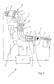
- control device 1 first of all comprises an apparatus 2 adapted to generate a flow 3 containing one or more polluting agents in an open internal environment of the industrial plant.
- such an apparatus 2 will be for example made up of an electric gun capable of generating a flow of detergent (solvents, mixtures of several detergents with or without water and/or steam, for example) to a high pressure which is directly addressed to the portion of the product 4 to be cleaned.
- detergent solvents, mixtures of several detergents with or without water and/or steam, for example
- the electric gun 2 will be provided with an actuating element 5 (in this particular case a push-button present on the handgrip) adapted to bring it from a non-operating rest condition (absence of flow and therefore of cleaning action) to an operating work condition in which spraying starts.
- an actuating element 5 in this particular case a push-button present on the handgrip
- the emitting device 6 is made up of at least one exhaust duct or pipe 7 which has an intake mouth 7a disposed at the internal environment and an outlet portion 7b which is generally placed close to an environment external to the plant.
- suction means 8 generally consisting of an appropriate fan or similar device capable of generating a flow in duct 7 consisting of an air mass from the internal environment directed to the environment external to the plant and therefore from the intake mouth 7a to the outlet portion 7b in the direction of arrows 9 shown in the figure.
- a filtering means 10 interposed between the intake mouth 7a and outlet portion 7b which is set to remove a predetermined amount of the polluting agents from the sucked air mass.
- this filtering means will consist of a predetermined number of activated-carbon filters arranged to be passed through by said flow so as to clean it.
- the air charged with solvent vapours passes through the activated-carbon filters that retain from 80 to 90 percent of the solvent.
- the residual solvent (still in the form of vapours) is conveyed along the disposal line that in turn can be provided with further filters.
- means for heat exchange 20 can be provided to enable the flow temperature to be varied during flow passage through the exhaust duct.
- the means for heat exchange can be of any kind, being specifically also adapted particular shapes of the exhaust duct 7 which are able to cause slowing down or at all events successive variations in the velocity of the flow (with a consequent heat exchange), to make temperature decrease to such an extent that precipitation of the polluting agents is caused.
- Such a device associated with a device for environmental control in industrial plants, in particular in plants for textile dry stain-removal, has proved to be by itself provided with novel and advantageous features as compared with the known art, i.e. independently of the use of automatic control means 11 evaluating the real operation of the emitting device 6.
- the device for environmental control being the object of the invention is also provided with automatic control means 11 active on the different components of the whole apparatus.
- the automatic control means 11 is set to carry out checking on good operation, efficiency and lack of tampering of the emitting device.
- First of all the control means is directed to check good operation of the activated-carbon filters.
- Said filters usually have an efficiency of about 90 percent with a yield of 20 percent by weight. This means that 100 kilos of activated carbons absorb 20 kilos of (liquid) solvent and retain 90 percent of possible vapours or gases.
- the automatic control means 11 is adapted to warn of the fact that the carbons are about to exhaust their absorbing action, by means of a signal light for example: the operator is given a sufficient work time to be able to replace them with new filters. This time elapsed (which time can vary from one to three hours, for example), the emitting device 6 stops and cannot be used any more until the activated-carbon filters 13 are replaced.
- control for depletion of filters 13 takes place by at least one sensor 12 which is able to evaluate the weight of the filters 13 themselves and generate a corresponding main control signal 12a when a main threshold value is overcome.
- the control means 11 deactivates the emitting device 6 and the corresponding apparatus 2 (electric gun) for generating a flow 3 containing the polluting agent.
- control for depletion of the activated carbons 13 is defined by a sealed system locking the apparatus when the activated carbons still have 5-10 per cent of their absorbing capacity. Obviously the physical portion of the system carrying out lock-out of the apparatus is sealed as well, and cannot be tampered from the outside without leaving evidence of the action.
- Sensor 12 is generally also capable of generating an auxiliary control signal 12b when an auxiliary threshold value linked to the filter weight as well, is overcome. Upon overcoming of this auxiliary threshold value the control means 11 warns in a visual, acoustic or any other appropriate manner, about the fact that exhaustion of the filtering power of filters 13 is taking place.
- the last-mentioned particular quality of the device is directed to enable easy and timely measures for replacement of the filters without stopping the working processes.
- the emitting device 6 then has at least one inlet valve 14 disposed at the intake mouth 7a of the exhaust duct 7 and at least one outlet valve 15 associated with the exhaust duct 7 at the outlet portion 7b.
- valves 14, 15 will be open to enable passage of the sucked air mass.
- the automatic control means 11 is also provided with at least one detection sensor 16 arranged to evaluate the presence or not of one or more polluting agents in the air mass being sucked from said internal environment so as to generate a corresponding signal 16a indicating the presence or absence of flow 3 and/or the polluting agent.
- This check which is carried out when the emitting device is active, enables to distinguish at least three operating conditions: a first condition of good operation in which the detection sensor detects the presence of flow 3 and/or of one or more polluting agents within the exhaust duct and enables operation of the emitting device 6; a second condition involving idling in which the absence of flow 3 and/or of a polluting agent in the sucked air mass is linked to non-operation of the electric gun 2; a third operating condition involving idling in which the electric gun 2 is active but the fluid flow containing the polluting agents is not directed to the intake mouth 7a and therefore the sucked air mass does not contain this flow and these substances.
- the signal indicating the absence of the polluting agent 16a causes the practically instantaneous lock-out of the emitting device 6 followed by closure of the inlet valve, preferably the outlet valve and followed by deactivation of the suction means 8.
- the activated-carbon filters used in the device are depleted, they are withdrawn and then regenerated by stripping, enabling subsequent reuses of same. Regeneration of the activated carbons enables four uses on an average in addition to the first one, thereby involving a great saving in terms of invested resources and environmental pollution.
- the solvent is recovered as well and can be either suitably drained or brought to the original conditions again and therefore reused too.
- the device herein described can also involve automatic signalling means (not shown in the figures) adapted to enable data sending carried out through the fixed or movable telephone system, the computer network or similar connections.
- This automatic signalling means is arranged to send, to a company entrusted with management/maintenance of the plant for example, corresponding information relating to good operation of the plant, depletion of the filters, lock-out of the emitting device and any other information which is useful for a good management of the plant itself.
- the suction means begins to automatically work in a predetermined period of time, in particular 3/5 seconds; at the same time the inlet valve 14 is opened to enable passage of the forced air mass which is thus conveyed to the activated-carbon filters 13.
- the air mass can be filtered once or several times depending on the operating requirements.
- the outlet valve 15 too is positioned to the operating working condition (opening).
- one or more detection sensors 16 evaluate the presence of flow 3 and/or one or more polluting agents in the air mass being sucked sending the corresponding signal 16a indicating the presence or absence 16a of a polluting agent.
- sensors 12 set to evaluate the filter weight in order to establish exhaustion or not of the filtering properties thereof send corresponding signals to the control means 11.
- control means 11 If all conditions required by the control means 11 are met (filters in good condition, operation with solvent suction, no tampering), the device for environmental control goes on with its correct operation enabling discharge of the purified or cleaned air mass to the outside (sequence enclosed by line A).
- the control means 11 sends a corresponding message, either of the visual type (pilot light) or of the acoustic type for example, to indicate that filters are to be replaced within a short period of time.
- the control means 11 commands closure of the inlet valve 14 and subsequently of the outlet valve 15; the same control means 11 stops operation of the suction means and the electric gun 2 thereby locking operation of the whole device. Practically in a relatively short period of time (5/8 seconds) the incorrect operation of the device is inhibited.
- the depleted filters are withdrawn, regenerated and possibly the polluting element/s (solvent) is regenerated as well (or at all events drained) and then the recovered elements are distributed again and reused if possible (sequence enclosed by line B).
- control means 11 will command closure of the inlet and outlet valves, locking the suction means and inhibiting use of the device and partial regeneration of the activated carbons to the detriment of the environment (sequence enclosed by line C).
Landscapes
- Chemical & Material Sciences (AREA)
- Chemical Kinetics & Catalysis (AREA)
- Engineering & Computer Science (AREA)
- Analytical Chemistry (AREA)
- General Chemical & Material Sciences (AREA)
- Oil, Petroleum & Natural Gas (AREA)
- Hydroponics (AREA)
- Greenhouses (AREA)
- Treating Waste Gases (AREA)
Applications Claiming Priority (2)
| Application Number | Priority Date | Filing Date | Title |
|---|---|---|---|
| ITMI20002379 IT1319084B1 (it) | 2000-11-03 | 2000-11-03 | Procedimento e relativo dispositivo per il controllo dell'ambiente inimpianti industriali |
| ITMI002379 | 2000-11-03 |
Publications (1)
| Publication Number | Publication Date |
|---|---|
| EP1203608A1 true EP1203608A1 (en) | 2002-05-08 |
Family
ID=11446084
Family Applications (1)
| Application Number | Title | Priority Date | Filing Date |
|---|---|---|---|
| EP01830670A Withdrawn EP1203608A1 (en) | 2000-11-03 | 2001-10-24 | Process and apparatus for removing pollutants from air in industrial plants |
Country Status (2)
| Country | Link |
|---|---|
| EP (1) | EP1203608A1 (it) |
| IT (1) | IT1319084B1 (it) |
Cited By (2)
| Publication number | Priority date | Publication date | Assignee | Title |
|---|---|---|---|---|
| WO2004047954A1 (en) * | 2002-11-23 | 2004-06-10 | Vet-Tech Solutions Limited | Gas filtering manifold and means for measuring the filter’s weight |
| FR3078896A1 (fr) * | 2018-03-19 | 2019-09-20 | Vinci Environnement | Dispositif de mesure de l'encrassement d'un filtre a manche |
Families Citing this family (1)
| Publication number | Priority date | Publication date | Assignee | Title |
|---|---|---|---|---|
| CN207301016U (zh) * | 2017-05-02 | 2018-05-01 | 国家电网公司 | 多功能瓦斯继电器气体回收试验装置 |
Citations (4)
| Publication number | Priority date | Publication date | Assignee | Title |
|---|---|---|---|---|
| US4297113A (en) * | 1980-03-03 | 1981-10-27 | Louis Theodore | Gas filtration apparatus |
| US4662899A (en) * | 1985-04-05 | 1987-05-05 | American Environmental International Inc. | Air pollution control system method and apparatus |
| US5389125A (en) * | 1993-08-20 | 1995-02-14 | Daniel D. Thayer | Automated system for recovery of VOC's from process air |
| DE19831313A1 (de) * | 1998-07-13 | 2000-01-20 | Andreas Noack | Thermosorptionssensor |
-
2000
- 2000-11-03 IT ITMI20002379 patent/IT1319084B1/it active
-
2001
- 2001-10-24 EP EP01830670A patent/EP1203608A1/en not_active Withdrawn
Patent Citations (5)
| Publication number | Priority date | Publication date | Assignee | Title |
|---|---|---|---|---|
| US4297113A (en) * | 1980-03-03 | 1981-10-27 | Louis Theodore | Gas filtration apparatus |
| US4662899A (en) * | 1985-04-05 | 1987-05-05 | American Environmental International Inc. | Air pollution control system method and apparatus |
| US4662899B1 (it) * | 1985-04-05 | 1990-01-16 | American Environmental Interna | |
| US5389125A (en) * | 1993-08-20 | 1995-02-14 | Daniel D. Thayer | Automated system for recovery of VOC's from process air |
| DE19831313A1 (de) * | 1998-07-13 | 2000-01-20 | Andreas Noack | Thermosorptionssensor |
Cited By (2)
| Publication number | Priority date | Publication date | Assignee | Title |
|---|---|---|---|---|
| WO2004047954A1 (en) * | 2002-11-23 | 2004-06-10 | Vet-Tech Solutions Limited | Gas filtering manifold and means for measuring the filter’s weight |
| FR3078896A1 (fr) * | 2018-03-19 | 2019-09-20 | Vinci Environnement | Dispositif de mesure de l'encrassement d'un filtre a manche |
Also Published As
| Publication number | Publication date |
|---|---|
| ITMI20002379A1 (it) | 2002-05-03 |
| IT1319084B1 (it) | 2003-09-23 |
Similar Documents
| Publication | Publication Date | Title |
|---|---|---|
| KR20080086633A (ko) | 집진장치 | |
| CN101844017A (zh) | 一种脉冲喷吹袋式收尘器破袋在线封堵装置 | |
| CN205549927U (zh) | 一种工业废气净化系统 | |
| EP1203608A1 (en) | Process and apparatus for removing pollutants from air in industrial plants | |
| CN206621949U (zh) | 染整定型机油烟废气净化处理系统 | |
| JP3442691B2 (ja) | エアーシヤワー装置 | |
| JPH05123515A (ja) | バグフイルタ装置の制御方法 | |
| US20020088480A1 (en) | Misted air cleaning system and related method | |
| CN105903304A (zh) | 一种节能环保除尘系统 | |
| CN110237631A (zh) | 湿式粉尘过滤器 | |
| JP4839815B2 (ja) | レンジフード | |
| CN218077105U (zh) | 一种浮法节能玻璃在线喷粉机除尘装置 | |
| KR101171229B1 (ko) | 수분침입을 방지하는 수단이 구비된 집진장치 | |
| CN212017095U (zh) | 一种脉冲布袋除尘装置 | |
| US5367840A (en) | Method and system for the abrasive cleaning of surfaces | |
| CN211302512U (zh) | 一种化工生产用喷淋塔 | |
| CN209792557U (zh) | 一种侧吸式连铸机切割排烟系统 | |
| KR200474368Y1 (ko) | 수분침입을 방지하는 수단이 구비된 집진장치 | |
| JP2831239B2 (ja) | バッグ式集塵装置のクリーニング制御方法 | |
| CN113713569A (zh) | 一种钢铁烧结机烟气净化装置 | |
| JP2003047816A6 (ja) | フィルタ監視装置及びフィルタ監視方法 | |
| CN220942262U (zh) | 一种应用于rto系统的不停机全自动阻火器清洗装置 | |
| JP2008095982A (ja) | 空気清浄システム | |
| CN205832861U (zh) | 一种节能环保除尘系统 | |
| CN208356418U (zh) | 一种脉冲滤桶除尘器 |
Legal Events
| Date | Code | Title | Description |
|---|---|---|---|
| PUAI | Public reference made under article 153(3) epc to a published international application that has entered the european phase |
Free format text: ORIGINAL CODE: 0009012 |
|
| AK | Designated contracting states |
Kind code of ref document: A1 Designated state(s): AT BE CH CY DE DK ES FI FR GB GR IE IT LI LU MC NL PT SE TR |
|
| AX | Request for extension of the european patent |
Free format text: AL;LT;LV;MK;RO;SI |
|
| AKX | Designation fees paid | ||
| REG | Reference to a national code |
Ref country code: DE Ref legal event code: 8566 |
|
| STAA | Information on the status of an ep patent application or granted ep patent |
Free format text: STATUS: THE APPLICATION IS DEEMED TO BE WITHDRAWN |
|
| 18D | Application deemed to be withdrawn |
Effective date: 20021109 |