EP1203624A2 - Verfahren zur Herstellung von Teilen eines Dachentwässerungssystemes und insbes. Etagenbogen - Google Patents
Verfahren zur Herstellung von Teilen eines Dachentwässerungssystemes und insbes. Etagenbogen Download PDFInfo
- Publication number
- EP1203624A2 EP1203624A2 EP01123938A EP01123938A EP1203624A2 EP 1203624 A2 EP1203624 A2 EP 1203624A2 EP 01123938 A EP01123938 A EP 01123938A EP 01123938 A EP01123938 A EP 01123938A EP 1203624 A2 EP1203624 A2 EP 1203624A2
- Authority
- EP
- European Patent Office
- Prior art keywords
- profile
- pipe
- bend
- walled
- drainage system
- Prior art date
- Legal status (The legal status is an assumption and is not a legal conclusion. Google has not performed a legal analysis and makes no representation as to the accuracy of the status listed.)
- Granted
Links
Images

Classifications
-
- F—MECHANICAL ENGINEERING; LIGHTING; HEATING; WEAPONS; BLASTING
- F16—ENGINEERING ELEMENTS AND UNITS; GENERAL MEASURES FOR PRODUCING AND MAINTAINING EFFECTIVE FUNCTIONING OF MACHINES OR INSTALLATIONS; THERMAL INSULATION IN GENERAL
- F16L—PIPES; JOINTS OR FITTINGS FOR PIPES; SUPPORTS FOR PIPES, CABLES OR PROTECTIVE TUBING; MEANS FOR THERMAL INSULATION IN GENERAL
- F16L9/00—Rigid pipes
- F16L9/17—Rigid pipes obtained by bending a sheet longitudinally and connecting the edges
-
- E—FIXED CONSTRUCTIONS
- E04—BUILDING
- E04D—ROOF COVERINGS; SKY-LIGHTS; GUTTERS; ROOF-WORKING TOOLS
- E04D13/00—Special arrangements or devices in connection with roof coverings; Protection against birds; Roof drainage ; Sky-lights
- E04D13/04—Roof drainage; Drainage fittings in flat roofs, balconies or the like
- E04D13/08—Down pipes; Special clamping means therefor
Definitions
- the invention relates to a method for producing components a roof drainage system, especially thin-walled gutter downpipes, Gutter drain pipe bend, floor bend and similar pipe parts made of a metal, being machined from a starting material Pipe profile created and then cut into lengths and further processed, in particular to arch forms and one produced in this process Floor bow.
- Gutter downspouts, gutter drain pipe bends and storey bends for rain gutter downspouts are usually made from a pipe material that usually has at least one longitudinal seam, mostly machine-made pipe material Rounding a preferably endless metal strip to a profile provided with a longitudinal slot and subsequent butt welding, in particular resistance welding, which are produced with respect to the longitudinal slot opposite longitudinal edges of the preformed profile.
- All of the parts of a roof drainage system manufactured in this known and customary manner have in common that all pipe shapes, regardless of whether downpipes or pipe bends, always have at least one longitudinal seam, which can be problematic in particular due to the peculiarities of the installation of a roof drainage system.
- the invention results from these disadvantages of previously known production methods initiating problem, a viable way of eliminating that on the The presence of seams, in particular on arch parts of the roof drainage system based on shortcomings of known types of production.
- the invention provides that the starting material for the production of a tubular profile at least essentially unformed Metal is and that from this unshaped metal in a first processing step a thin-walled and seamless tubular profile is formed and that in one or several subsequent processing steps seamless pipe profile and parts of a roof drainage system, such as downpipe shots, gutter drain pipe bends, storey bends and the like be shaped.
- extrusion process is recommended for the process of producing a seamless tube profile.
- a thick-walled tube material can be used as the starting material, which is extruded into a seamless, thin-walled tube material.
- extrusion forming leads on the one hand to a seamless tubular material that has a homogeneous structure over its circumference and on the other hand can be carried out with a tolerable mechanical and economic outlay.
- the extrusion results in a tube profile which, after being formed into an elbow or in a straight form, can be expanded in some areas, in particular at the end, without any risk of bursting or becoming leaky.
- the structure of the seamless pipe material produced by the extrusion process is oriented in the flow direction and in the pipe longitudinal direction, such pipe material is particularly well suited for further forming using a stretch-pull process.
- a thick-walled tube material as the starting material, it is naturally also possible to use any other form of starting material which can be deformed by extrusion.
- the procedure according to the invention is outstandingly suitable for the production of components of a roof drainage system to be formed from a non-ferrous metal, in particular copper or aluminum or zinc, by means of cold extrusion.
- a specific tubular profile is produced with different wall thicknesses over its circumference, preferably in such a way that the tubular profile in its wall area assigned to the outer circumference of a tubular elbow has a larger extension
- the floor arch is characterized in particular by the fact that it at least in Area between its successively oppositely curved areas is equipped with at least one embossing of its peripheral wall.
- the peripheral wall of the floor arch in an at least more or less rectilinear area between its successively oppositely curved areas with two local limited and arranged opposite each other with respect to the pipe axis only include a deformation of its outer surface structure Is embossed, although it can be recommended that the embossments arranged opposite one another with respect to the tube axis the first a manufacturer symbol or manufacturer name and the second one preferably technical name of the bow, such as type or size or the like represents.
- the peripheral wall of the multi-level arch is provided with an at least partially circumferential embossing in the area between its successively curved regions, the embossing consisting of one or more at least the outer circumferential surface of the multi-level arch opposite raised ring ribs or recessed grooves can exist, which extend, possibly with interruptions over the pipe circumference.
- embossing patterns can also be used, such as a combination of grooves or ribs and symbols.
- its peripheral wall is additionally equipped with a further embossing in the region of at least one of its two ends, this embossing also being accommodated in a rectilinear end region of the floor arch.
- the further embossing of the circumferential wall of a bend in the area of one of its ends can consist of two partial embossments arranged opposite one another with respect to the tube axis, one of the two embossings being a manufacturer designation or a manufacturer symbol and the opposite embossing a type or size or. Material name, possibly also an indication of the material quality of the sheet.
- the embossing can also be made neutral and quite simply as only at least partially, optionally also as a fully circumferential embossing, for example in the form of at least one rib or groove or the like his.
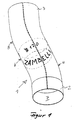
- the floor arch 1 essentially consists of two straight end regions 2 and 3, which each have an arcuate curvature 4 or 5 into one also pass straight middle section 6.
- One 2 of the two end areas of the floor arch 1 is with an expansion 7 for inserting one in the Provide drawing not shown subsequent pipeline part.
- the storey arch shown in FIG. 1 with two references embossments arranged opposite one another on its tube axis equipped, the one 9 of the two embossments a manufacturer symbol or the manufacturer's name and the opposite embossing 10 a technical name, here represents a diameter.
- two are also relevant embossing 9 and 10 are provided in the central region 6, of which one 9 is a manufacturer symbol or a manufacturer name and the other 10 represents a diameter. additionally for these two embossments 9 and 10 there is one in the central region 6 further embossing with circumferential grooves 11 and partially circumferential Grooves 12 provided. Furthermore, in this embodiment, the one with Widening provided opposite end region 3 in turn with a Embossed, which in the embodiment shown from a number circumferential grooves.
Landscapes
- Engineering & Computer Science (AREA)
- General Engineering & Computer Science (AREA)
- Mechanical Engineering (AREA)
- Architecture (AREA)
- Civil Engineering (AREA)
- Structural Engineering (AREA)
- Extrusion Moulding Of Plastics Or The Like (AREA)
- Rigid Pipes And Flexible Pipes (AREA)
- Shaping Of Tube Ends By Bending Or Straightening (AREA)
- Sink And Installation For Waste Water (AREA)
Abstract
Description
Insgesamt ist der Einsatz von Schweißnähten an Rohrformen eines Dachentwässerungssystemes immer mit dem Risiko einer unzulänglichen Qualität der Schweißnaht bzw. einer Undichtheit der Schweißnaht verbunden, was eine ständige Kontrolle der Schweißnähte und damit einen erheblichen Aufwand erfordert
Der Einsatz des Fließpress-Umformens führt zum einen zu einem über seinen Umfang hin ein homogenes Gefüge aufweisenden und nahtlosen Rohrmaterial und kann zum anderen mit einem erträglichen mechanischen und wirtschaftlichen Aufwand ausgeführt werden. Insbesondere ergibt das Fließpressen ein Rohrprofil, welches nach seiner Umformung zu Rohrbogen oder aber auch in einer geraden Form ohne jede Gefahr eines Aufplatzens oder Undichtwerdens bereichsweise, insbesondere endseitig aufweitbar ist. Da das Gefüge des im Wege des Fließpressverfahrens hergestellten nahtlosen Rohrmaterials in Fließrichtung und in Rohrlängsrichtung ausgerichtet ist eignet sich solches Rohrmaterial in besonders hervorragender Weise zur Weiteren Umformung unter Anwendung eines Streck-Ziehverfahrens.
Anstelle der Verwendung eines dickwandigen Rohrmaterials als Ausgangsmaterial kann naturgemäß auch jede andere Form eines im Wege des Fließpressens umformbaren Ausgangsmaterials eingesetzt werden. Insbesondere eignet sich die erfindungsgemäße Verfahrensweise in hervorragender Weise zur Herstellung von aus einem NE-Metall, insbesondere Kupfer oder Aluminium bzw. Zink, zu formenden Bestandteilen eines Dachentwässerungssystemes im Wege des Kalt-Fließpressens.
In diesem Zusammenhang kann weiter vorgesehen sein, daß für die Herstellung von Bogen oder Etagenbogen bestimmtes Rohrprofil mit über seinen Umfang hin unterschiedlichen Wandungsstärken hergestellt wird, vorzugsweise in der Art, daß das Rohrprofil in seinem dem Außenumfang eines Rohrbogens zugeordneten Wandungsbereich eine der erforderlichen Streckung entsprechende größere Wandungsstärke besitzt, während das Rohrprofil in seinem dem Innenumfang eines Rohrbogens zugeordneten Wandungsbereich eine geringere Wandungsstärke aufweist, so daß in diesem Bereich möglicherweise auftretende Stauchfalten wenig Material enthalten und daher in einfacher Weise geglättet werden können.
Selbstverständlich kann auch eine Mischform unterschiedlicher Prägungsbilder verwendet werden, wie beispielsweise eine Kombination von Rillen oder Rippen und Symbolen.
Unabhängig von einer solchen bevorzugten speziellen Ausbildung der Prägung in der Umfangswandung eines Etagenbogens kann die Prägung aber auch neutral ausgeführt sein und ganz einfach als lediglich wenigstens teilweise, gegebenenfalls auch als voll umlaufende Prägung, beispielsweise in Form wenigstens einer Rippe oder Rille bzw. dergl. ausgebildet sein.
Claims (15)
- Verfahren zur Herstellung von Bestandteilen eines Dachentwässerungssystemes, insbesondere von dünnwandigen Regenrinnenfallrohrern, Regenrinnenablauf-Rohrbogen, Etagenbogen und dergl. Rohrleitungsteilen aus einem Metall, wobei aus einem Ausgangsmaterial maschinell ein Rohrprofil erstellt und nachfolgend in Längenabschnitte abgelängt sowie weiter bearbeitet, insbesondere zu Bogenformen geformt wird
dadurch gekennzeichnet, daß das Ausgangsmaterial zumindest im Wesentlichen ungeformtes Metall ist und daß aus diesem ungeformten Metall in einem ersten Bearbeitungsschritt ein nahtloses Rohrprofil geformt wird und daß in einem oder mehreren nachfolgenden Bearbeitungsschritten Längenabschnitte dieses nahtlosen Rohrprofiles zu Teilen eines Dachentwässerungssystemes, wie Fallrohrschüsse, Regenrinnenablauf-Rohrbogen, Etagenbogen und dergl geformt werden. - Verfahren nach Anspruch 1, dadurch gekennzeichnet, daß das Formen des nahtlosen Rohrprofiles im Wege des Fließpressens, insbesondere Kaltfließpressens erfolgt.
- Verfahren nach Anspruch 1, dadurch gekennzeichnet, daß das Umformen des geraden Rohrprofiles zu Regenrinnenablauf-Rohrbogen oder Etagenbogen im Wege eines Streck-Ziegvorganges erfolgt
- Verfahren nach Anspruch 1, dadurch gekennzeichnet, daß zur Herstellung von Regenrinnenablauf-Rohrbogen bestimmtes Rohrprofil mit über seinen Umfang hin unterschiedlichen Wandungsstärken ausgestattet wird
- Verfahren nach Anspruch 1, dadurch gekennzeichnet, daß dem der Ausformung eines Bogens zugeordneten Streck-Ziehvorgang ein Glättvorgang, insbesondere hinsichtlich der innenliegenden Wandung eine Rohrbogens nachgeschaltet ist.
- Verfahren nach Anspruch 1, dadurch gekennzeichnet, daß bei dessen einseitiger Einspannung zur Ausformung eines Rohrbogens in einem Streck-Ziehvorgang ein einen der beabsichtigten Krümmung des Bogens entsprechenden Durchmesser aufweisendes bogenförmiges Widerlager und ein in das Rohrprofil eingreifender, drehangetriebene Rollen aufweisender Formkopf eingesetzt werden.
- Verfahren nach Anspruch 1, dadurch gekennzeichnet, daß als Ausgangsmaterial für die Erzeugung eines dünnwandigen, nahtlosen Rohrprofiles dickwandiges Rohrmaterial verwendet wird.
- Verfahren nach Anspruch 1, dadurch gekennzeichnet, daß es zur Herstellung von aus NE-Metallen zu bildenden Bestandteilen eines Dachentwässerungssystemes eingesetzt ist.
- Im Verfahren nach Anspruch 1 bis 8 hergestellter Etagenbogen für ein Dachentwässerungssystem, welches aus dünnwandigen untereinander durch Zusammenstecken verbindbaren Teilen besteht und hauptsächlich gerade, dünnwandige Regenrinnenfallrohre, gleichartig dünnwandige Regenrinnenablauf-Rohrbogen sowie ferner gleichartig dünnwandige Etagenbogen, d.h. aufeinanderfolgend in zwei entgegengesetzte Richtungen gekrümmte Abschnitte aufweisende Rohrleitungsteile, besteht und bei dem alle Teile aus einem Metallblech gebildet sind,
dadurch gekennzeichnet, daß alle Rohrleitungsteile des Dachentwässerungssystemes, Regenrinnenfallrohre, Regenrinnenablauf-Rohrbogen und Etagenbogen einheitlich aus einem maschinell gefertigten Rohrprofil bestehen und das Rohrprofil durch runden eines ebenen, vorzugsweise endlosen Metallbandes zu einem mit einem in Längsrichtung verlaufenden Längsschlitz versehenen Rohrprofil und nachfolgendes Stumpfschweißen, insbesondere Widerstandsschweißen, der einander bezüglich des Längsschlitzes gegenüberliegenden Längsränder des vorgeformten Rohrprofiles gebildet ist. - Etagenbogen nach Anspruch 9, dadurch gekennzeichnet, daß seine Umfangswandung zumindest im Bereich zwischen seinen aufeinanderfolgend entgegengesetzt gekrümmten Bereichen mit wenigstens einer, vorzugsweise mit zwei einander bezüglich der Rohrachse gegenüberliegend angeordneten Prägungen seiner Umfangswandung ausgestattet ist.
- Etagenbogen nach Anspruch 9 und 10, dadurch gekennzeichnet, daß von den einander bezüglich der Rohrachse gegenüberliegend angeordneten Prägungen die erste ein Herstellersymbol bzw. Herstellernamen und die zweite eine Bezeichnung des Bogens darstellt.
- Etagenbogen nach Anspruch 9 bis 11, dadurch gekennzeichnet, daß seine Umfangswandung im Bereich zwischen seinen aufeinanderfolgend entgegengesetzt gekrümmten Bereichen mit einer wenigstens teilweise umlaufenden, insbesondere rillenförmigen Prägung versehen ist, wobei die Prägungen insbesondere teils aus rillenförmigen und teils mit symbolartigen Elementen bestehen.
- Etagenbogen nach einem der Ansprüche 9 bis 12, dadurch gekennzeichnet, daß seine Umfangswandung zusätzlich im Bereich wenigstens eines seiner beiden Enden mit mindestens einer weiteren Prägung, insbesondere einer aus zwei einander bezüglich der Rohrachse gegenüberliegend angeordneten Teilprägungen bestehenden Prägung ausgestattet ist, .
- Etagenbogen nach einem der Ansprüche 1 bis 9, dadurch gekennzeichnet, daß er in einem Fließpress-Ziehvorgang aus einem geradlinigen Rohrmaterialabschnitt hergestellt ist und die Fließrichtung des Materials zumindest im Bereich des Außenumfanges der beiden zueinander entgegengesetzt gerichteten Krümmungsbereiche des den Etagenbogen ergebenden Rohrmaterialabschnittes gleichgerichtet ist.
- Etagenbogen nach einem der Ansprüche 9 bis 14, dadurch gekennzeichnet, daß die Prägungen seiner Umfangswandung lediglich eine Verformung seiner äußeren Oberflächenstruktur umfassen.
Applications Claiming Priority (4)
| Application Number | Priority Date | Filing Date | Title |
|---|---|---|---|
| DE10054958 | 2000-11-06 | ||
| DE10054958 | 2000-11-06 | ||
| DE20022075U DE20022075U1 (de) | 2000-10-27 | 2000-12-29 | Etagenbogen |
| DE20022075U | 2000-12-29 |
Publications (3)
| Publication Number | Publication Date |
|---|---|
| EP1203624A2 true EP1203624A2 (de) | 2002-05-08 |
| EP1203624A3 EP1203624A3 (de) | 2003-01-02 |
| EP1203624B1 EP1203624B1 (de) | 2005-04-27 |
Family
ID=26007582
Family Applications (1)
| Application Number | Title | Priority Date | Filing Date |
|---|---|---|---|
| EP01123938A Expired - Lifetime EP1203624B1 (de) | 2000-11-06 | 2001-10-08 | Verfahren zur Herstellung von Teilen eines Dachentwässerungssystemes und insbes. Etagenbogen |
Country Status (2)
| Country | Link |
|---|---|
| EP (1) | EP1203624B1 (de) |
| AT (1) | ATE294033T1 (de) |
Family Cites Families (8)
| Publication number | Priority date | Publication date | Assignee | Title |
|---|---|---|---|---|
| US1916645A (en) * | 1932-10-24 | 1933-07-04 | Taylor James Hall | Method of and means for making curved pipe fittings |
| GB456970A (en) * | 1935-04-15 | 1936-11-16 | William Eckford | Improvements in and relating to the marking by embossing of pipes of lead and lead alloys |
| DE2855449A1 (de) * | 1978-12-21 | 1980-07-03 | Vitkovice Zelezarny | Verfahren zur erzeugung von rohrkruemmern, kniestuecken und rohrspiralen und vorrichtung zur durchfuehrung dieses verfahrens |
| JPS57139424A (en) * | 1981-02-25 | 1982-08-28 | Sumitomo Metal Ind Ltd | Manufacture of elbow provided with straight pipe part |
| DE8626975U1 (de) * | 1986-10-10 | 1987-03-26 | Norsk Hydro A.S., Oslo | Hohlprofil aus Nichteisenmetallen und deren Legierungen mit kalt-verformten Biegungen |
| JPH07109805A (ja) * | 1993-10-12 | 1995-04-25 | Sekisui Chem Co Ltd | 自在エルボ |
| JPH07292897A (ja) * | 1994-04-27 | 1995-11-07 | Sekisui Chem Co Ltd | 竪樋部品 |
| DE20022075U1 (de) * | 2000-10-27 | 2001-06-07 | Zambelli, Franz, 94481 Grafenau | Etagenbogen |
-
2001
- 2001-10-08 AT AT01123938T patent/ATE294033T1/de not_active IP Right Cessation
- 2001-10-08 EP EP01123938A patent/EP1203624B1/de not_active Expired - Lifetime
Also Published As
| Publication number | Publication date |
|---|---|
| ATE294033T1 (de) | 2005-05-15 |
| EP1203624B1 (de) | 2005-04-27 |
| EP1203624A3 (de) | 2003-01-02 |
Similar Documents
| Publication | Publication Date | Title |
|---|---|---|
| EP1648631A1 (de) | Verfahren zum herstellen eines längsgeschlitzten hohlprofils mit mehreren, im querschnitt verschiedenen längsabschnitten aus einer ebenen blechplatine | |
| EP1280649B1 (de) | Verfahren zur herstellung von mehrschicht-metall-verbundrohren | |
| CH639182A5 (de) | Verfahren zur herstellung schraubenfoermig gewickelter rohre und danach hergestelltes rohr. | |
| EP2212039B1 (de) | Verfahren zum herstellen eines profils aus flachem metallband | |
| EP0445904B1 (de) | Verfahren zur Herstellung eines metallischen, dickwandigen Hochdruckrohres | |
| DE4214557C2 (de) | ||
| DE10047231C1 (de) | Verfahren und Vorrichtung zur Herstellung eines Rohres mit partiell unterschiedlichen Wandstärken | |
| EP2725272B1 (de) | Hülse für unlösbare Verbindung, Verfahren zur Herstellung einer Hülse und System mit einer Hülse | |
| EP1278001B1 (de) | Pressverbindung zwischen einem Fitting und einem Rohrende | |
| EP1203624A2 (de) | Verfahren zur Herstellung von Teilen eines Dachentwässerungssystemes und insbes. Etagenbogen | |
| DE10248356A1 (de) | Verfahren und Vorrichtung zur Herstellung einer gewichtsoptimierten Luftreifenfelge | |
| DE102013013735B4 (de) | Vorrichtung und Verfahren zur Herstellung eines Wickelfalzrohres sowie ein mit der Vorrichtung und nach dem Verfahren aus einem profilierten Metallband hergestelltes Wickelfalzrohr | |
| EP2169290A2 (de) | Profilrohr | |
| DE20022075U1 (de) | Etagenbogen | |
| EP2177282A1 (de) | Belastungsangepasstes Strukturteil aus Metall für einen Wärmetauscher, Verfahren zur Herstellung eines belastungsangepassten Strukturteils | |
| DE102009052118B4 (de) | Verfahren zur Herstellung eines Rohrverbinders | |
| DE68902423T2 (de) | Schraubennahtrohre. | |
| EP0182001A2 (de) | Verfahren und Vorrichtung zum Herstellen eines flexiblen Wellrohres sowie nach dem Verfahren hergestelltes flexibles Wellrohr | |
| DE2609570A1 (de) | Verfahren zur herstellung von regenrinnenablaufbogen und nach diesem verfahren hergestellter regenrinnenablaufbogen | |
| DE69203030T2 (de) | Verfahren zur Herstellung von dünnwandigen Rohrkrümmern. | |
| DE102004038856A1 (de) | Verfahren zum Walzen von Metallteilen | |
| DE102021110492A1 (de) | Vorrichtung und Verfahren zur Herstellung eines doppelwandigen Rohres | |
| DE2147169A1 (de) | Verfahren zur herstellung eines kaefigs fuer zylindrische waelzkoerper | |
| DE1777410C3 (de) | Verfahren zur Herstellung von auf der äußeren Mantelfläche mit Rechtsund Linksgewinde und an der Innenwand mit zwei diametralen Schlüsselnocken versehenen Nippeln | |
| DE102006002003A1 (de) | Anbindungsvorrichtung für zumindest ein Führungsrohr an zumindest eine Führungsschiene, insbesondere eines Schiebedaches |
Legal Events
| Date | Code | Title | Description |
|---|---|---|---|
| PUAI | Public reference made under article 153(3) epc to a published international application that has entered the european phase |
Free format text: ORIGINAL CODE: 0009012 |
|
| 17P | Request for examination filed |
Effective date: 20011008 |
|
| AK | Designated contracting states |
Kind code of ref document: A2 Designated state(s): AT BE CH CY DE DK ES FI FR GB GR IE IT LI LU MC NL PT SE TR |
|
| AX | Request for extension of the european patent |
Free format text: AL;LT;LV;MK;RO;SI |
|
| PUAL | Search report despatched |
Free format text: ORIGINAL CODE: 0009013 |
|
| AK | Designated contracting states |
Kind code of ref document: A3 Designated state(s): AT BE CH CY DE DK ES FI FR GB GR IE IT LI LU MC NL PT SE TR |
|
| AX | Request for extension of the european patent |
Free format text: AL;LT;LV;MK;RO;SI |
|
| RIC1 | Information provided on ipc code assigned before grant |
Free format text: 7B 21C 23/08 A, 7B 21C 37/06 B, 7B 21C 37/28 B |
|
| AKX | Designation fees paid |
Designated state(s): AT BE CH CY DE DK ES FI FR GB GR IE IT LI LU MC NL PT SE TR |
|
| GRAP | Despatch of communication of intention to grant a patent |
Free format text: ORIGINAL CODE: EPIDOSNIGR1 |
|
| 17Q | First examination report despatched |
Effective date: 20040802 |
|
| GRAS | Grant fee paid |
Free format text: ORIGINAL CODE: EPIDOSNIGR3 |
|
| GRAA | (expected) grant |
Free format text: ORIGINAL CODE: 0009210 |
|
| AK | Designated contracting states |
Kind code of ref document: B1 Designated state(s): AT BE CH CY DE DK ES FI FR GB GR IE IT LI LU MC NL PT SE TR |
|
| PG25 | Lapsed in a contracting state [announced via postgrant information from national office to epo] |
Ref country code: IT Free format text: LAPSE BECAUSE OF FAILURE TO SUBMIT A TRANSLATION OF THE DESCRIPTION OR TO PAY THE FEE WITHIN THE PRE;WARNING: LAPSES OF ITALIAN PATENTS WITH EFFECTIVE DATE BEFORE 2007 MAY HAVE OCCURRED AT ANY TIME BEFORE 2007. THE CORRECT EFFECTIVE DATE MAY BE DIFFERENT FROM THE ONE RECORDED.SCRIBED TIME-LIMIT Effective date: 20050427 Ref country code: NL Free format text: LAPSE BECAUSE OF FAILURE TO SUBMIT A TRANSLATION OF THE DESCRIPTION OR TO PAY THE FEE WITHIN THE PRESCRIBED TIME-LIMIT Effective date: 20050427 Ref country code: IE Free format text: LAPSE BECAUSE OF FAILURE TO SUBMIT A TRANSLATION OF THE DESCRIPTION OR TO PAY THE FEE WITHIN THE PRESCRIBED TIME-LIMIT Effective date: 20050427 Ref country code: TR Free format text: LAPSE BECAUSE OF FAILURE TO SUBMIT A TRANSLATION OF THE DESCRIPTION OR TO PAY THE FEE WITHIN THE PRESCRIBED TIME-LIMIT Effective date: 20050427 Ref country code: FI Free format text: LAPSE BECAUSE OF FAILURE TO SUBMIT A TRANSLATION OF THE DESCRIPTION OR TO PAY THE FEE WITHIN THE PRESCRIBED TIME-LIMIT Effective date: 20050427 Ref country code: GB Free format text: LAPSE BECAUSE OF FAILURE TO SUBMIT A TRANSLATION OF THE DESCRIPTION OR TO PAY THE FEE WITHIN THE PRESCRIBED TIME-LIMIT Effective date: 20050427 |
|
| REG | Reference to a national code |
Ref country code: GB Ref legal event code: FG4D Free format text: NOT ENGLISH |
|
| REG | Reference to a national code |
Ref country code: CH Ref legal event code: EP |
|
| REG | Reference to a national code |
Ref country code: IE Ref legal event code: FG4D Free format text: LANGUAGE OF EP DOCUMENT: GERMAN |
|
| PG25 | Lapsed in a contracting state [announced via postgrant information from national office to epo] |
Ref country code: SE Free format text: LAPSE BECAUSE OF FAILURE TO SUBMIT A TRANSLATION OF THE DESCRIPTION OR TO PAY THE FEE WITHIN THE PRESCRIBED TIME-LIMIT Effective date: 20050727 Ref country code: DK Free format text: LAPSE BECAUSE OF FAILURE TO SUBMIT A TRANSLATION OF THE DESCRIPTION OR TO PAY THE FEE WITHIN THE PRESCRIBED TIME-LIMIT Effective date: 20050727 Ref country code: GR Free format text: LAPSE BECAUSE OF FAILURE TO SUBMIT A TRANSLATION OF THE DESCRIPTION OR TO PAY THE FEE WITHIN THE PRESCRIBED TIME-LIMIT Effective date: 20050727 |
|
| PG25 | Lapsed in a contracting state [announced via postgrant information from national office to epo] |
Ref country code: ES Free format text: LAPSE BECAUSE OF FAILURE TO SUBMIT A TRANSLATION OF THE DESCRIPTION OR TO PAY THE FEE WITHIN THE PRESCRIBED TIME-LIMIT Effective date: 20050807 |
|
| REF | Corresponds to: |
Ref document number: 50106022 Country of ref document: DE Date of ref document: 20050818 Kind code of ref document: P |
|
| PG25 | Lapsed in a contracting state [announced via postgrant information from national office to epo] |
Ref country code: CY Free format text: LAPSE BECAUSE OF FAILURE TO SUBMIT A TRANSLATION OF THE DESCRIPTION OR TO PAY THE FEE WITHIN THE PRESCRIBED TIME-LIMIT Effective date: 20051008 Ref country code: AT Free format text: LAPSE BECAUSE OF NON-PAYMENT OF DUE FEES Effective date: 20051008 |
|
| PG25 | Lapsed in a contracting state [announced via postgrant information from national office to epo] |
Ref country code: PT Free format text: LAPSE BECAUSE OF FAILURE TO SUBMIT A TRANSLATION OF THE DESCRIPTION OR TO PAY THE FEE WITHIN THE PRESCRIBED TIME-LIMIT Effective date: 20051010 |
|
| PG25 | Lapsed in a contracting state [announced via postgrant information from national office to epo] |
Ref country code: MC Free format text: LAPSE BECAUSE OF NON-PAYMENT OF DUE FEES Effective date: 20051031 Ref country code: BE Free format text: LAPSE BECAUSE OF NON-PAYMENT OF DUE FEES Effective date: 20051031 Ref country code: LI Free format text: LAPSE BECAUSE OF NON-PAYMENT OF DUE FEES Effective date: 20051031 Ref country code: CH Free format text: LAPSE BECAUSE OF NON-PAYMENT OF DUE FEES Effective date: 20051031 Ref country code: LU Free format text: LAPSE BECAUSE OF NON-PAYMENT OF DUE FEES Effective date: 20051031 |
|
| NLV1 | Nl: lapsed or annulled due to failure to fulfill the requirements of art. 29p and 29m of the patents act | ||
| GBV | Gb: ep patent (uk) treated as always having been void in accordance with gb section 77(7)/1977 [no translation filed] |
Effective date: 20050427 |
|
| REG | Reference to a national code |
Ref country code: IE Ref legal event code: FD4D |
|
| PLBE | No opposition filed within time limit |
Free format text: ORIGINAL CODE: 0009261 |
|
| STAA | Information on the status of an ep patent application or granted ep patent |
Free format text: STATUS: NO OPPOSITION FILED WITHIN TIME LIMIT |
|
| 26N | No opposition filed |
Effective date: 20060130 |
|
| PG25 | Lapsed in a contracting state [announced via postgrant information from national office to epo] |
Ref country code: DE Free format text: LAPSE BECAUSE OF NON-PAYMENT OF DUE FEES Effective date: 20060503 |
|
| REG | Reference to a national code |
Ref country code: CH Ref legal event code: PL |
|
| EN | Fr: translation not filed | ||
| BERE | Be: lapsed |
Owner name: ZAMBELLI -FERTIGUNGS-GMBH Effective date: 20051031 |
|
| PG25 | Lapsed in a contracting state [announced via postgrant information from national office to epo] |
Ref country code: FR Free format text: LAPSE BECAUSE OF NON-PAYMENT OF DUE FEES Effective date: 20051031 |
|
| PG25 | Lapsed in a contracting state [announced via postgrant information from national office to epo] |
Ref country code: FR Free format text: LAPSE BECAUSE OF NON-PAYMENT OF DUE FEES Effective date: 20050427 |