EP1203667A2 - Aufzeichnungskopf mit Flüssigkeitsausstoss - Google Patents
Aufzeichnungskopf mit Flüssigkeitsausstoss Download PDFInfo
- Publication number
- EP1203667A2 EP1203667A2 EP01126023A EP01126023A EP1203667A2 EP 1203667 A2 EP1203667 A2 EP 1203667A2 EP 01126023 A EP01126023 A EP 01126023A EP 01126023 A EP01126023 A EP 01126023A EP 1203667 A2 EP1203667 A2 EP 1203667A2
- Authority
- EP
- European Patent Office
- Prior art keywords
- filter
- recording head
- liquid
- ink
- liquid ejection
- Prior art date
- Legal status (The legal status is an assumption and is not a legal conclusion. Google has not performed a legal analysis and makes no representation as to the accuracy of the status listed.)
- Granted
Links
- 239000007788 liquid Substances 0.000 title claims abstract description 91
- 238000011144 upstream manufacturing Methods 0.000 claims abstract description 8
- 239000002657 fibrous material Substances 0.000 claims abstract description 5
- 238000003825 pressing Methods 0.000 claims description 61
- 239000000835 fiber Substances 0.000 claims description 20
- 239000002184 metal Substances 0.000 claims 1
- 229920000914 Metallic fiber Polymers 0.000 description 9
- 239000004743 Polypropylene Substances 0.000 description 6
- 238000003466 welding Methods 0.000 description 6
- 238000004519 manufacturing process Methods 0.000 description 5
- 230000002093 peripheral effect Effects 0.000 description 5
- 230000008901 benefit Effects 0.000 description 4
- 238000005245 sintering Methods 0.000 description 4
- 239000000463 material Substances 0.000 description 3
- 238000000034 method Methods 0.000 description 3
- 229920005989 resin Polymers 0.000 description 3
- 239000011347 resin Substances 0.000 description 3
- 238000009941 weaving Methods 0.000 description 3
- 230000002745 absorbent Effects 0.000 description 2
- 239000002250 absorbent Substances 0.000 description 2
- 230000008094 contradictory effect Effects 0.000 description 2
- 230000006872 improvement Effects 0.000 description 2
- -1 polypropylene Polymers 0.000 description 2
- 229920001155 polypropylene Polymers 0.000 description 2
- 229920005992 thermoplastic resin Polymers 0.000 description 2
- 230000002411 adverse Effects 0.000 description 1
- 238000005452 bending Methods 0.000 description 1
- 238000009835 boiling Methods 0.000 description 1
- 230000008859 change Effects 0.000 description 1
- 238000006073 displacement reaction Methods 0.000 description 1
- 239000010408 film Substances 0.000 description 1
- 230000004048 modification Effects 0.000 description 1
- 238000012986 modification Methods 0.000 description 1
- 239000004745 nonwoven fabric Substances 0.000 description 1
- 230000008569 process Effects 0.000 description 1
- 238000011084 recovery Methods 0.000 description 1
- 239000010409 thin film Substances 0.000 description 1
Images


Classifications
-
- B—PERFORMING OPERATIONS; TRANSPORTING
- B41—PRINTING; LINING MACHINES; TYPEWRITERS; STAMPS
- B41J—TYPEWRITERS; SELECTIVE PRINTING MECHANISMS, i.e. MECHANISMS PRINTING OTHERWISE THAN FROM A FORME; CORRECTION OF TYPOGRAPHICAL ERRORS
- B41J2/00—Typewriters or selective printing mechanisms characterised by the printing or marking process for which they are designed
- B41J2/005—Typewriters or selective printing mechanisms characterised by the printing or marking process for which they are designed characterised by bringing liquid or particles selectively into contact with a printing material
- B41J2/01—Ink jet
- B41J2/17—Ink jet characterised by ink handling
- B41J2/175—Ink supply systems ; Circuit parts therefor
- B41J2/17503—Ink cartridges
- B41J2/1752—Mounting within the printer
- B41J2/17523—Ink connection
-
- B—PERFORMING OPERATIONS; TRANSPORTING
- B41—PRINTING; LINING MACHINES; TYPEWRITERS; STAMPS
- B41J—TYPEWRITERS; SELECTIVE PRINTING MECHANISMS, i.e. MECHANISMS PRINTING OTHERWISE THAN FROM A FORME; CORRECTION OF TYPOGRAPHICAL ERRORS
- B41J2/00—Typewriters or selective printing mechanisms characterised by the printing or marking process for which they are designed
- B41J2/005—Typewriters or selective printing mechanisms characterised by the printing or marking process for which they are designed characterised by bringing liquid or particles selectively into contact with a printing material
- B41J2/01—Ink jet
- B41J2/135—Nozzles
- B41J2/14—Structure thereof only for on-demand ink jet heads
-
- B—PERFORMING OPERATIONS; TRANSPORTING
- B41—PRINTING; LINING MACHINES; TYPEWRITERS; STAMPS
- B41J—TYPEWRITERS; SELECTIVE PRINTING MECHANISMS, i.e. MECHANISMS PRINTING OTHERWISE THAN FROM A FORME; CORRECTION OF TYPOGRAPHICAL ERRORS
- B41J2/00—Typewriters or selective printing mechanisms characterised by the printing or marking process for which they are designed
- B41J2/005—Typewriters or selective printing mechanisms characterised by the printing or marking process for which they are designed characterised by bringing liquid or particles selectively into contact with a printing material
- B41J2/01—Ink jet
- B41J2/17—Ink jet characterised by ink handling
- B41J2/175—Ink supply systems ; Circuit parts therefor
- B41J2/17503—Ink cartridges
- B41J2/17513—Inner structure
Definitions
- the present invention relates to a liquid ejection recording head for placing liquid such as ink on recording medium such as paper.
- the ink ejecting performance of a recording head which ejects small ink droplets is easily affected by foreign objects which have entered the recording head.
- the recording head is provided with a filter, which is placed in the ink path of the recording head.
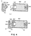
- the ink container 42 comprises: an external shell with an air vent 422 and an ink outlet 421; an absorbent member 423 stored in the shell; and a pressing member 307 placed in contact with the ink outlet 421 for guiding outward the ink within the ink container 42.
- the recording head 41 is provided with a liquid inlet 301 (ink supply tube), which is a part of a liquid guiding path 301 for supplying ink to an ink ejecting portion 411.
- the outward end of the liquid inlet 301 (liquid guiding path 302) is provided with a filter 303, the center portion of which protrudes slightly outward of the liquid inlet 301.
- Figure 3 is an enlarged sectional view of the outward end portion of the liquid guiding path 302, the ink outlet 421, and their adjacencies.
- the ink outlet 421 of the ink container is provided with the pressing member 307, and the ink is supplied to the recording head through the contact between the filter 303 and pressing member 307.
- the filter 303 is located at the outermost end of the ink guiding path 302, the periphery of the filter 303 being covered with resin, as disclosed in Japanese Laid-Open Patent Application 6-238910, to prevent the occurrences of such problems as the filter 303 becoming separated from the liquid inlet 301, and the fiber ends exposed at the periphery of the filter damaging the pressing member.
- the filter 303 is fixed to the outermost end of the ink guiding path 302 by thermally bending inward the edge of the ink inlet of the recording head, which is formed of thermoplastic resin.
- the filter is shaped so that the center portion of the filter spherically bulges outward to assure that the center portion of the filter comes into contact with the pressing member ( Figure 3(b)).
- a conventional filter formed by weaving metallic fibers is flexible, but flat in its natural state. Thus, it is welded to the resin portion so that the center portion of the filter remains flexed outward of the liquid inlet. Since the filter is flexible, it deforms as it is pressed by the pressing member, preventing air from remaining (entering) between the filter and pressing member.
- the filter grade should be selected according to the diameter of the orifices through which ink droplets are ejected.
- a conventional filter formed by weaving metallic fibers is not satisfactory in terms of foreign object removal performance. More specifically, in order to remove finer foreign objects, the metallic fibers must be made finer, and the finer the metallic fibers, the weaker the filter. In other words, it is difficult to make a filter which is strong and yet does not easily clog. Thus, in order to provide a filter which is strong and yet does not easily clog, it become necessary to replace the conventional filter material with such a material that is stronger and yet is less likely to clog than the conventional filter material.
- a filter formed by sintering metallic fibers layered like the fibers in nonwoven fabric has come into use as a replacement for a conventional filter, due to its advantage that it is finer in mesh and its multilayer structure makes it less likely to clog.
- a sintered filter lacks flexibility, and therefore, it is difficult to make the center portion of a sintered filter permanently protrude outward of the liquid inlet of a liquid ejection recording head when attaching the filter to the resinous portion of the liquid inlet.
- a sintered filter must be shaped so that its center portion permanently protrudes in the direction corresponding to the outward direction of the liquid inlet ink, prior to the attachment of the filter to the resinous portion of the liquid inlet.
- the center portion of a sintered filter protrudes, in the case of a sintered filter with a small diameter, for example, no more than approximately 5 mm, the center portion of the sintered filter will be in the form of a circular frustum, being flat on top, surrounded by the flat peripheral portion of the filter, in consideration of the issues regarding the manufacturing of the sintered filter, for example, the accuracy in a pressing process.
- a pressing member formed by parallelly binding polypropylene fibers in such a manner that the fiber direction matches the ink flow direction has come into use as a replacement for a conventional pressing member, due to its advantage that it is higher in fiber density, being therefore capable of generating stronger capillary force, and also, being capable of preventing the pressure loss from increasing.
- the above described filter formed by sintering is poor in flexibility compared to the woven filter, it is difficult to sinter a filter capable of conforming to the contour of the pressing member as does a conventional woven filter.
- a pressing member formed of bound PP fibers is higher in density, and its fibers are perpendicular to the interface between the pressing member and filter. Therefore, the pressing member formed of bound PP fibers is not as flexible as a conventional filter, at the interface, failing to making satisfactory contact with a filter, as shown in Figure 3(d).
- the configuration of the contact portions of the two components, and their positions relative to each other, are much more important than they used to be. Further, the contact pressure between the filter and pressing member must be properly adjusted. In other words, there is much to be improved regarding the filter for a liquid ejection recording apparatus, in terms of the stability in ink supply performance and yield in its mass production.
- ink flows at a higher speed than during a normal printing operation.
- the filter and pressing member are not properly in contact with each other, it is possible that air will be sucked into the liquid guiding path. If air is sucked into the ink supply path by a large amount, the ink supply to the ejection orifices is interrupted, resulting in unsatisfactory printing performance.
- the primary object of the present invention is to keep the filter of the ink inlet of a liquid ejection recording head properly in contact with the virtually flat contact surface of the pressing member of a liquid supply container, in order to make it possible to provide a liquid ejection recording head superior in terms of the stability in ink delivery performance and also in terms of yield in its mass production.
- the present invention for accomplishing the above objects relates to a liquid ejection recording head, which is provided with a filter attached to the entrance of the liquid guiding path of the recording head, and receives liquid from one or more ink containers, which are mounted on a carriage, and the liquid outlet of which comprises a pressing member, which is formed of fibers and contacts the filter of the recording head.
- the present invention is characterized in that the portion of the filter of the liquid ejection recording head, which contacts the pressing member of the ink container, projects outward of the ink guiding path of the recording head, relative to the periphery of the filter by which the filter is attached to the recording head, and is virtually flat.
- the present invention includes a liquid ejection recording head, the filter of which is such a filter that is produced by sintering metallic fibers.
- a filter for the above described liquid ejection recording head may be such a filter that even before the filter is attached to the recording head, the center portion of the filter projects outward of the liquid guiding path of the recording head, relative to the periphery of the filter, and the center portion of the filter, which contacts the pressing member of an ink container, is virtually flat, or such a filter that before it is attached to the recording head, its center portion which comes into contact with the aforementioned pressing member, spherically protrudes outward relative to its periphery, but after the filter is fixed to the entrance of the liquid guiding path of the liquid ejection recording head, its center portion is made flat by pressing.
- the diameter of the center portion of the above described filter is desired to be greater than the size of the cross-section of the liquid guiding path of the recording head, on the inward side of the filter.
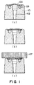
- FIG. 1 is a sectional view of the ink inlet portion of the recording head in the first embodiment of the present invention.
- the inkjet recording head in this embodiment has an ink inlet path (liquid flow path) 102, which is in the cylindrical ink inlet 101 of the inkjet recording head.
- a filter 103 has been thermally welded. More specifically, the outward end of the ink inlet is provided with two types of ribs (unshown) which are located at the peripheral portion of the outward end of the ink inlet path 102.
- the filter 103 is welded.
- the ribs of he other type covers the periphery of the filter 103 in a manner to wrap it.
- the outward end of the ink inlet is also provided with a plurality of pillars, which are configured to support the filter 103 from the inward side of the filter 103 as the filter 103 is fixed to the outward end of the ink inlet by its periphery.
- the filter 103 After the filter 103 is placed in the slightly recessed portion of the end portion of the ink inlet of the recording head, it is fixed to the outward end of the ink inlet portion, by thermally deforming the aforementioned ribs located at the periphery of the ink inlet, that is, those constituting the filter fixing portion ( Figure 1(a)).
- the center portion of the filter 103 which is the portion of the filter 103 by which the filter 103 contacts the contact surface of the pressing member 107 formed of bound PP fibers, and is spherically protruding outward of the ink inlet of the recording head, is flattened by pressing.
- the pressing member 107 and filter 103 can be properly placed in contact with each other regardless of the hardness of the contact surface of the pressing member 107.
- the distance by which the center portion of the filter 103 is pressed is adjusted so that the portion of the center portion of the filter 103, which will be flattened by pressing, will be outward of the peripheral portion of the filter 103 after the flattening.
- the diameter of the ink inlet path, on the immediately inward side of the filter 103, is rendered smaller than the diameter of the flat portion of the outward end of the ink inlet of the recording head, which the pressing member 107 contacts. Therefore, it is further assured that even when the velocity at which ink flows through the ink flow path suddenly changes due to the execution of the recording head performance recovery process in which ink is aggressively suctioned, air bubbles are not suctioned into the ink path.
- FIG. 2 is a sectional view of the ink inlet of the recording head in the second embodiment of the present invention.
- the inkjet recording head in this embodiment is provided with a liquid inlet path 202, which is located within the cylindrical ink inlet portion 201 of the recording head.
- the outward end of the ink inlet path 202 is provided with a filter 203, which is thermally welded thereto.
- a filter When a filter is large in diameter, it can be shaped so that its center portion protrudes outward in the form of a frustum, being flat at the center portion, before its thermal welding to the recording head.
- the portion of the outwardly protruding portion of the filter 203, which contacts the pressing member, is rendered flat, eliminating the need for pressing the filter 203 to flatten its center portion after the welding of the filter 203 ( Figure 2(a)).
- the filter 203 can be attached to the cylindrical ink inlet portion 201 of the recording head by thermally deforming the cover rib 205 after properly positioned the filter 203, which is flat across its contact portion, or the center portion, relative to the ink inlet portion ( Figure 2(b)).
- the filter 203 and the pressing member 207 can be kept properly in contact with each other, regardless of the surface hardness of the pressing member 207 ( Figure 2(c)).
- the present invention applicable to an inkjet recording head which ejects liquid droplets from its nozzles by using the film boiling phenomenon which occurs as thermal energy is applied to liquid, but also an inkjet recording head which ejects liquid from its nozzles by using the microscopic displacement which occurs to elements in the form of thin film, as an electrical signal is inputted into the elements.
- a liquid ejection recording head having a liquid inlet, through which the head is supplied with the liquid from the liquid outlet, comprising a pressing member formed of fibers, of an ink container, and a filter with which the liquid inlet is fitted
- the filter is shaped like a frustum so that the portion of the filter, which contacts the pressing member, projects outward relative to the peripheral portion of the filter by which the filter is fixed to the liquid inlet, and also becomes virtually flat, making it possible for the filter to remain properly in contact with the flat contact surface of the pressing member. Therefore, it is possible to obtain a liquid ejection recording head which is reliable in terms of filter performance (regarding the capillary force of the pressing member), and is excellent in terms of the stability in ink supply.
- the present invention is particularly effective when applied to a liquid ejection recording head which is connected to a liquid container, the pressing member of which is formed of parallelly bound fibers. Needless to say, it is not contradictory to the gist of the present invention to apply the present invention to a liquid ejection recording head which is connected to a liquid container, the pressing member of which is formed of relatively soft fibrous material such as felt.
- the present invention is effectively applicable to a liquid ejection recording head which employs a hard filter produced by sintering.
- the application of the present invention to a filter produced by weaving metallic fibers is not contradictory to the gist of the present invention, which is obvious.
- the combination which benefits most from the present invention is the combination of a pressing member formed of parallelly bound fibers, and a sintered filter.
- the present invention is also applicable to a combination of a pressing member formed of parallelly bound fibers, and a filter formed of woven metallic fibers, or a combination of pressing member formed of felt or the like, and a sintered filter or a metallic fiber filter.
- a liquid ejection recording head which receives liquid from one or more liquid containers mounted on a carriage, the liquid container having a press-contact member of fibrous material at a liquid outlet, the liquid ejection recording head includes a tubular member for receiving ink from the liquid container, the tubular member being provided with an upstream edge with respect to a direction of flow of the liquid therethrough; a filter provided in the tubular member and having an outer surface press-contactable to the press-contact member, the outer surface being a substantially flat surface and being outward beyond the upstream edge of the tubular member.
Landscapes
- Ink Jet (AREA)
Applications Claiming Priority (2)
| Application Number | Priority Date | Filing Date | Title |
|---|---|---|---|
| JP2000336220 | 2000-11-02 | ||
| JP2000336220A JP2002137410A (ja) | 2000-11-02 | 2000-11-02 | 液体吐出記録ヘッド |
Publications (3)
| Publication Number | Publication Date |
|---|---|
| EP1203667A2 true EP1203667A2 (de) | 2002-05-08 |
| EP1203667A3 EP1203667A3 (de) | 2003-03-05 |
| EP1203667B1 EP1203667B1 (de) | 2006-12-27 |
Family
ID=18811834
Family Applications (1)
| Application Number | Title | Priority Date | Filing Date |
|---|---|---|---|
| EP01126023A Expired - Lifetime EP1203667B1 (de) | 2000-11-02 | 2001-10-31 | Aufzeichnungskopf mit Flüssigkeitsausstoss |
Country Status (4)
| Country | Link |
|---|---|
| US (1) | US6592215B2 (de) |
| EP (1) | EP1203667B1 (de) |
| JP (1) | JP2002137410A (de) |
| DE (1) | DE60125490T2 (de) |
Cited By (1)
| Publication number | Priority date | Publication date | Assignee | Title |
|---|---|---|---|---|
| EP2883703A4 (de) * | 2012-08-08 | 2016-12-28 | Seiko Epson Corp | Flüssigkeitslagerbehälter und flüssigkeitsversorgungssystem |
Families Citing this family (10)
| Publication number | Priority date | Publication date | Assignee | Title |
|---|---|---|---|---|
| JP4018578B2 (ja) | 2003-03-27 | 2007-12-05 | キヤノン株式会社 | 液体吐出ヘッドカートリッジ |
| US7625072B2 (en) * | 2004-07-22 | 2009-12-01 | Canon Kabushiki Kaisha | Ink jet recording head and recording apparatus |
| US7273275B2 (en) * | 2004-11-29 | 2007-09-25 | Lexmark International, Inc. | Air funneling inkjet printhead |
| US8066363B2 (en) * | 2005-03-31 | 2011-11-29 | Lexmark International, Inc. | Printhead filter systems and methods for manufacturing the same |
| US7926928B2 (en) * | 2005-08-24 | 2011-04-19 | Brother Kogyo Kabushiki Kaisha | Droplet ejection apparatus and inkjet recording apparatus |
| JP4854281B2 (ja) * | 2005-11-29 | 2012-01-18 | キヤノン株式会社 | 記録ヘッド、インクタンク、記録ヘッドの製造方法 |
| EP2346697B1 (de) * | 2008-10-30 | 2012-08-01 | Hewlett-Packard Development Company, L.P. | Fluidverbindung für fluidausstosssystem |
| JP2013180523A (ja) * | 2012-03-02 | 2013-09-12 | Seiko Epson Corp | カートリッジ |
| JP6976735B2 (ja) | 2017-06-15 | 2021-12-08 | キヤノン株式会社 | 液体吐出ヘッドおよび液体吐出装置と液体吐出ヘッドの取付方法 |
| JP7191602B2 (ja) | 2018-09-10 | 2022-12-19 | キヤノン株式会社 | 液体吐出装置 |
Citations (2)
| Publication number | Priority date | Publication date | Assignee | Title |
|---|---|---|---|---|
| JPH05345425A (ja) | 1992-06-16 | 1993-12-27 | Canon Inc | 記録カートリッジおよびインクジェット記録装置 |
| JPH06238910A (ja) | 1992-12-25 | 1994-08-30 | Canon Inc | 液体噴射ヘッドおよび該液体噴射ヘッド使用の液体噴射装置 |
Family Cites Families (7)
| Publication number | Priority date | Publication date | Assignee | Title |
|---|---|---|---|---|
| JPH01133747A (ja) | 1987-11-20 | 1989-05-25 | Canon Inc | 液体噴射記録ヘッド |
| CA2085550C (en) * | 1991-12-19 | 1999-07-06 | Kentaro Yano | Method of controlling an ink-jet recording apparatus according to recording head information, and ink-jet recording apparatus in which the method is implemented |
| EP0603902B1 (de) | 1992-12-25 | 2000-05-24 | Canon Kabushiki Kaisha | Flüssigkeitstrahlkopf und Vorrichtung dafür |
| DE69331791T2 (de) * | 1993-07-20 | 2002-10-10 | Canon K.K., Tokio/Tokyo | Tintenstrahlaufzeichnungsgerät, welches eine Farbkartusche mit einem tinteninduzierenden Element verwendet |
| ES2162881T3 (es) * | 1994-07-06 | 2002-01-16 | Canon Kk | Contenedor de tinta, cabezal para chorros de tinta con contenedor para la tinta, aparato para la impresion por chorros de tinta con contenedor para la tinta y metodo de fabricacion del contenedor para la tinta. |
| US6082852A (en) * | 1996-04-23 | 2000-07-04 | Fuji Xerox Co., Ltd | Recording apparatus, printer, and an ink tank therein |
| JP3236566B2 (ja) | 1998-11-12 | 2001-12-10 | セイコーインスツルメンツ株式会社 | ヘッドホルダ、該ヘッドホルダに用いるフィルタの固定方法、及びインクジェット式記録装置 |
-
2000
- 2000-11-02 JP JP2000336220A patent/JP2002137410A/ja active Pending
-
2001
- 2001-10-31 EP EP01126023A patent/EP1203667B1/de not_active Expired - Lifetime
- 2001-10-31 DE DE60125490T patent/DE60125490T2/de not_active Expired - Lifetime
- 2001-11-01 US US09/985,112 patent/US6592215B2/en not_active Expired - Fee Related
Patent Citations (2)
| Publication number | Priority date | Publication date | Assignee | Title |
|---|---|---|---|---|
| JPH05345425A (ja) | 1992-06-16 | 1993-12-27 | Canon Inc | 記録カートリッジおよびインクジェット記録装置 |
| JPH06238910A (ja) | 1992-12-25 | 1994-08-30 | Canon Inc | 液体噴射ヘッドおよび該液体噴射ヘッド使用の液体噴射装置 |
Cited By (2)
| Publication number | Priority date | Publication date | Assignee | Title |
|---|---|---|---|---|
| EP2883703A4 (de) * | 2012-08-08 | 2016-12-28 | Seiko Epson Corp | Flüssigkeitslagerbehälter und flüssigkeitsversorgungssystem |
| US9561664B2 (en) | 2012-08-08 | 2017-02-07 | Seiko Epson Corporation | Liquid storage container and liquid supply system |
Also Published As
| Publication number | Publication date |
|---|---|
| DE60125490T2 (de) | 2007-10-04 |
| US20020060726A1 (en) | 2002-05-23 |
| DE60125490D1 (de) | 2007-02-08 |
| EP1203667A3 (de) | 2003-03-05 |
| EP1203667B1 (de) | 2006-12-27 |
| US6592215B2 (en) | 2003-07-15 |
| JP2002137410A (ja) | 2002-05-14 |
Similar Documents
| Publication | Publication Date | Title |
|---|---|---|
| EP0887190B1 (de) | Tintenstrahlaufzeichnungsvorrichtung | |
| US6592215B2 (en) | Liquid ejection recording head | |
| JP4141523B2 (ja) | インク供給流路の弁装置 | |
| US6582064B2 (en) | Fluid ejection device having an integrated filter and method of manufacture | |
| JP2004148509A (ja) | 液体噴射ヘッド | |
| JP2009000733A (ja) | プレス加工方法、パンチングプレート、および、液体噴射ヘッド | |
| JPH11291513A (ja) | インクジェット式記録装置 | |
| JP3521578B2 (ja) | インクジェットプリンタ | |
| JP4193891B2 (ja) | インクカートリッジ、および、そのインク充填方法 | |
| JP2001113698A (ja) | ノズルプレート及びその製造方法及びインクジェット記録ヘッド | |
| US8052267B2 (en) | Inlet structure and assembly method | |
| CN102202901A (zh) | 用于流体喷射系统的流体互连件 | |
| CN101157306A (zh) | 墨罐和使用这种墨罐的喷墨打印机 | |
| JP4131292B2 (ja) | インク供給流路の弁装置 | |
| JP4048859B2 (ja) | インクカートリッジ及びその製造方法 | |
| JP3389942B2 (ja) | インクジェット式記録ヘッド | |
| JPS629428B2 (de) | ||
| JPH07241989A (ja) | インクジェットプリントヘッド | |
| JP4359897B2 (ja) | インクカートリッジ及びその製造方法 | |
| JP4629904B2 (ja) | インクジェット式記録装置 | |
| JP2005289074A (ja) | 液体噴射ヘッド | |
| JP4321149B2 (ja) | インク供給針、このインク供給針を備えたインクジェットプリンタ及びインク供給装置。 | |
| JP2006095961A (ja) | インクタンク | |
| JP2012228795A (ja) | 液体吐出ヘッド、液体吐出ヘッドの製造方法、及びフィルターの固定方法 | |
| JP2006240245A (ja) | フィルタ溶着方法および液体吐出ヘッドカートリッジ |
Legal Events
| Date | Code | Title | Description |
|---|---|---|---|
| PUAI | Public reference made under article 153(3) epc to a published international application that has entered the european phase |
Free format text: ORIGINAL CODE: 0009012 |
|
| 17P | Request for examination filed |
Effective date: 20011031 |
|
| AK | Designated contracting states |
Kind code of ref document: A2 Designated state(s): AT BE CH CY DE DK ES FI FR GB GR IE IT LI LU MC NL PT SE TR |
|
| AX | Request for extension of the european patent |
Free format text: AL;LT;LV;MK;RO;SI |
|
| PUAL | Search report despatched |
Free format text: ORIGINAL CODE: 0009013 |
|
| AK | Designated contracting states |
Kind code of ref document: A3 Designated state(s): AT BE CH CY DE DK ES FI FR GB GR IE IT LI LU MC NL PT SE TR |
|
| AX | Request for extension of the european patent |
Extension state: AL LT LV MK RO SI |
|
| AKX | Designation fees paid |
Designated state(s): DE FR GB IT |
|
| 17Q | First examination report despatched |
Effective date: 20031212 |
|
| GRAP | Despatch of communication of intention to grant a patent |
Free format text: ORIGINAL CODE: EPIDOSNIGR1 |
|
| GRAS | Grant fee paid |
Free format text: ORIGINAL CODE: EPIDOSNIGR3 |
|
| GRAA | (expected) grant |
Free format text: ORIGINAL CODE: 0009210 |
|
| AK | Designated contracting states |
Kind code of ref document: B1 Designated state(s): DE FR GB IT |
|
| PG25 | Lapsed in a contracting state [announced via postgrant information from national office to epo] |
Ref country code: IT Free format text: LAPSE BECAUSE OF FAILURE TO SUBMIT A TRANSLATION OF THE DESCRIPTION OR TO PAY THE FEE WITHIN THE PRESCRIBED TIME-LIMIT;WARNING: LAPSES OF ITALIAN PATENTS WITH EFFECTIVE DATE BEFORE 2007 MAY HAVE OCCURRED AT ANY TIME BEFORE 2007. THE CORRECT EFFECTIVE DATE MAY BE DIFFERENT FROM THE ONE RECORDED. Effective date: 20061227 |
|
| REG | Reference to a national code |
Ref country code: GB Ref legal event code: FG4D |
|
| REF | Corresponds to: |
Ref document number: 60125490 Country of ref document: DE Date of ref document: 20070208 Kind code of ref document: P |
|
| EN | Fr: translation not filed | ||
| PLBE | No opposition filed within time limit |
Free format text: ORIGINAL CODE: 0009261 |
|
| STAA | Information on the status of an ep patent application or granted ep patent |
Free format text: STATUS: NO OPPOSITION FILED WITHIN TIME LIMIT |
|
| 26N | No opposition filed |
Effective date: 20070928 |
|
| PG25 | Lapsed in a contracting state [announced via postgrant information from national office to epo] |
Ref country code: FR Free format text: LAPSE BECAUSE OF FAILURE TO SUBMIT A TRANSLATION OF THE DESCRIPTION OR TO PAY THE FEE WITHIN THE PRESCRIBED TIME-LIMIT Effective date: 20070817 |
|
| PG25 | Lapsed in a contracting state [announced via postgrant information from national office to epo] |
Ref country code: FR Free format text: LAPSE BECAUSE OF FAILURE TO SUBMIT A TRANSLATION OF THE DESCRIPTION OR TO PAY THE FEE WITHIN THE PRESCRIBED TIME-LIMIT Effective date: 20061227 |
|
| PGFP | Annual fee paid to national office [announced via postgrant information from national office to epo] |
Ref country code: GB Payment date: 20141021 Year of fee payment: 14 Ref country code: DE Payment date: 20141031 Year of fee payment: 14 |
|
| REG | Reference to a national code |
Ref country code: DE Ref legal event code: R119 Ref document number: 60125490 Country of ref document: DE |
|
| GBPC | Gb: european patent ceased through non-payment of renewal fee |
Effective date: 20151031 |
|
| PG25 | Lapsed in a contracting state [announced via postgrant information from national office to epo] |
Ref country code: DE Free format text: LAPSE BECAUSE OF NON-PAYMENT OF DUE FEES Effective date: 20160503 Ref country code: GB Free format text: LAPSE BECAUSE OF NON-PAYMENT OF DUE FEES Effective date: 20151031 |