EP1203686B1 - Ensemble de composants pour l'évacuation des vapeurs de carburant d'un réservoir de carburant - Google Patents
Ensemble de composants pour l'évacuation des vapeurs de carburant d'un réservoir de carburant Download PDFInfo
- Publication number
- EP1203686B1 EP1203686B1 EP01125861A EP01125861A EP1203686B1 EP 1203686 B1 EP1203686 B1 EP 1203686B1 EP 01125861 A EP01125861 A EP 01125861A EP 01125861 A EP01125861 A EP 01125861A EP 1203686 B1 EP1203686 B1 EP 1203686B1
- Authority
- EP
- European Patent Office
- Prior art keywords
- component
- slots
- forming
- tank
- projections
- Prior art date
- Legal status (The legal status is an assumption and is not a legal conclusion. Google has not performed a legal analysis and makes no representation as to the accuracy of the status listed.)
- Expired - Lifetime
Links
- 239000000446 fuel Substances 0.000 title claims description 27
- 239000002828 fuel tank Substances 0.000 title claims description 21
- 238000013022 venting Methods 0.000 title claims description 3
- 239000000463 material Substances 0.000 claims description 29
- 238000000034 method Methods 0.000 claims description 10
- 238000007654 immersion Methods 0.000 claims description 7
- 229920001903 high density polyethylene Polymers 0.000 claims description 6
- 239000004700 high-density polyethylene Substances 0.000 claims description 6
- 238000003466 welding Methods 0.000 claims description 5
- 239000004952 Polyamide Substances 0.000 claims description 3
- 229920002647 polyamide Polymers 0.000 claims description 3
- 229920001470 polyketone Polymers 0.000 claims description 3
- 238000001746 injection moulding Methods 0.000 claims 1
- 239000007788 liquid Substances 0.000 description 5
- 239000004033 plastic Substances 0.000 description 3
- 229920003023 plastic Polymers 0.000 description 3
- 230000002035 prolonged effect Effects 0.000 description 3
- 230000008961 swelling Effects 0.000 description 3
- DHKHKXVYLBGOIT-UHFFFAOYSA-N 1,1-Diethoxyethane Chemical compound CCOC(C)OCC DHKHKXVYLBGOIT-UHFFFAOYSA-N 0.000 description 1
- 239000011354 acetal resin Substances 0.000 description 1
- 230000001154 acute effect Effects 0.000 description 1
- 239000000945 filler Substances 0.000 description 1
- 238000003780 insertion Methods 0.000 description 1
- 230000037431 insertion Effects 0.000 description 1
- 238000004519 manufacturing process Methods 0.000 description 1
- 238000012986 modification Methods 0.000 description 1
- 230000004048 modification Effects 0.000 description 1
- 229920006324 polyoxymethylene Polymers 0.000 description 1
- 238000003860 storage Methods 0.000 description 1
- 230000003313 weakening effect Effects 0.000 description 1
Images


Classifications
-
- B—PERFORMING OPERATIONS; TRANSPORTING
- B60—VEHICLES IN GENERAL
- B60K—ARRANGEMENT OR MOUNTING OF PROPULSION UNITS OR OF TRANSMISSIONS IN VEHICLES; ARRANGEMENT OR MOUNTING OF PLURAL DIVERSE PRIME-MOVERS IN VEHICLES; AUXILIARY DRIVES FOR VEHICLES; INSTRUMENTATION OR DASHBOARDS FOR VEHICLES; ARRANGEMENTS IN CONNECTION WITH COOLING, AIR INTAKE, GAS EXHAUST OR FUEL SUPPLY OF PROPULSION UNITS IN VEHICLES
- B60K15/00—Arrangement in connection with fuel supply of combustion engines or other fuel consuming energy converters, e.g. fuel cells; Mounting or construction of fuel tanks
- B60K15/03—Fuel tanks
- B60K15/035—Fuel tanks characterised by venting means
- B60K15/03519—Valve arrangements in the vent line
-
- B—PERFORMING OPERATIONS; TRANSPORTING
- B60—VEHICLES IN GENERAL
- B60K—ARRANGEMENT OR MOUNTING OF PROPULSION UNITS OR OF TRANSMISSIONS IN VEHICLES; ARRANGEMENT OR MOUNTING OF PLURAL DIVERSE PRIME-MOVERS IN VEHICLES; AUXILIARY DRIVES FOR VEHICLES; INSTRUMENTATION OR DASHBOARDS FOR VEHICLES; ARRANGEMENTS IN CONNECTION WITH COOLING, AIR INTAKE, GAS EXHAUST OR FUEL SUPPLY OF PROPULSION UNITS IN VEHICLES
- B60K15/00—Arrangement in connection with fuel supply of combustion engines or other fuel consuming energy converters, e.g. fuel cells; Mounting or construction of fuel tanks
- B60K15/03—Fuel tanks
- B60K2015/03328—Arrangements or special measures related to fuel tanks or fuel handling
- B60K2015/03453—Arrangements or special measures related to fuel tanks or fuel handling for fixing or mounting parts of the fuel tank together
-
- Y—GENERAL TAGGING OF NEW TECHNOLOGICAL DEVELOPMENTS; GENERAL TAGGING OF CROSS-SECTIONAL TECHNOLOGIES SPANNING OVER SEVERAL SECTIONS OF THE IPC; TECHNICAL SUBJECTS COVERED BY FORMER USPC CROSS-REFERENCE ART COLLECTIONS [XRACs] AND DIGESTS
- Y10—TECHNICAL SUBJECTS COVERED BY FORMER USPC
- Y10T—TECHNICAL SUBJECTS COVERED BY FORMER US CLASSIFICATION
- Y10T137/00—Fluid handling
- Y10T137/0318—Processes
- Y10T137/0402—Cleaning, repairing, or assembling
- Y10T137/0441—Repairing, securing, replacing, or servicing pipe joint, valve, or tank
- Y10T137/0447—Including joint or coupling
-
- Y—GENERAL TAGGING OF NEW TECHNOLOGICAL DEVELOPMENTS; GENERAL TAGGING OF CROSS-SECTIONAL TECHNOLOGIES SPANNING OVER SEVERAL SECTIONS OF THE IPC; TECHNICAL SUBJECTS COVERED BY FORMER USPC CROSS-REFERENCE ART COLLECTIONS [XRACs] AND DIGESTS
- Y10—TECHNICAL SUBJECTS COVERED BY FORMER USPC
- Y10T—TECHNICAL SUBJECTS COVERED BY FORMER US CLASSIFICATION
- Y10T137/00—Fluid handling
- Y10T137/598—With repair, tapping, assembly, or disassembly means
-
- Y—GENERAL TAGGING OF NEW TECHNOLOGICAL DEVELOPMENTS; GENERAL TAGGING OF CROSS-SECTIONAL TECHNOLOGIES SPANNING OVER SEVERAL SECTIONS OF THE IPC; TECHNICAL SUBJECTS COVERED BY FORMER USPC CROSS-REFERENCE ART COLLECTIONS [XRACs] AND DIGESTS
- Y10—TECHNICAL SUBJECTS COVERED BY FORMER USPC
- Y10T—TECHNICAL SUBJECTS COVERED BY FORMER US CLASSIFICATION
- Y10T137/00—Fluid handling
- Y10T137/8593—Systems
- Y10T137/86348—Tank with internally extending flow guide, pipe or conduit
Definitions
- the present invention relates to fuel system components such as, for example, fuel vapor flow control valves for use in liquid fuel tanks employed in motor vehicles.
- fuel system components such as, for example, fuel vapor flow control valves for use in liquid fuel tanks employed in motor vehicles.
- valves for controlling the flow of fuel vapor from the fuel tank to a storage canister and also to provide valves capable of closing the vent in the event the vehicle is tipped beyond a threshold amount or rolled from the upright position.
- problems have been encountered in forming the components of materials which are acceptably dimensionally stable when immersed in the fuel and yet which are compatible with the fuel tank.
- the choice of the materials for the fuel tank is generally dictated by the fabricating processes employed and a need for materials which may be welded together. Unfortunately, it has been found that the properties of the materials employed for the components immersed in the fuel are not compatible with welding attachment to the fuel tank materials.
- EP 0 879727 A1 discloses a valve unit for a motor vehicle fuel supply system including a valve housing and a cover for the housing having means for connection to a service duct of the vehicle.
- the cover is separate from the housing and made from a material compatible with that of the tank or filler pipe, so that it can be welded directly to an aperture of an element of the fuel-supply system of the vehicle.
- Releasable retaining means are provided for attaching the cover to the housing that is preferably made from an acetal-resin based plastic material.
- the releasable retaining means comprise retaining elements formed integrally on the outer wall of the cylindrical housing and adapted to cooperate with corresponding seats formed in a cylindrical skirt of the cover to allow the housing to be coupled to the cover.
- said retaining means may comprise projections on the skirt and corresponding seats formed in the housing nested therein.
- US 5,404,907 A reveals a weldable vapor vent valve for fuel tanks comprising a heat-resistant valve body and a weldable connector portion fastened to an upper end of the valve body for welding onto the outer surface of a polymeric fuel tank.
- the weldable connector and the valve body are manufactured separately and heat stake posts are provided extending from the underside of the weldable connector for heat-staking to the valve body.
- connection means in the form of a snap-fit structures are provided to lock the weldable connector physically to the valve body.
- WO 98/50717 illustrates a tank venting control system comprising a valve assembly for controlling discharge of fuel vapor from a vehicle fuel tank.
- Said valve assembly of which various embodiments are disclosed comprises an exterior component weldable to a fuel tank and at least one interior component.
- Connecting means in the form of heat stakes or snap-fit structures are provided to attach the two-components to one another. It has long been desired to provide a way or means of attaching fuel system components which are designed for immersion in the fuel to the remaining components of the system which are designed to be attached and secured onto the tank by weldment. The problem has been particularly acute in finding a way or means of attaching fuel vapor flow control valves and rollover valves to fuel tanks formed of plastic material.
- the present invention as it is defined in claims 1 and 10, respectively, provides a solution to the problem of attaching fuel system components to a fuel tank where the components intended to extend interiorly of the tank and immersed in the fuel are formed of different material from the components intended for attachment exteriorly of the tank and particularly those intended for attachment to the tank by weldment.
- the present invention employs an exterior component formed of material suitable for weldment to a fuel tank and an interior component formed of different material suitable for prolonged immersion in the liquid fuel in the tank in which the interior component is attached to the exterior component prior to assembly onto the tank.
- the present invention employs an exterior component which has a plurality of projections or lugs extending downwardly therefrom in a spaced array; and, the interior component has a correspondingly spaced array of radially extending slots with the sides of the slots having engagement surfaces, preferably barbs formed thereon for push-in attachment over the lugs on the exterior component.
- the barbs are preferably of harder material and deform the lugs to retain them in position.
- the radial slots with their barbed edges permit swelling and expansion of the immersed component and sliding of the lugs on the barbs without weakening or loosening of the engagement of the barbs on the projecting lugs.
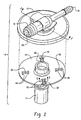
- the assembly of the present invention is indicated generally at 10 which includes an exterior component 12 formed of material suitable to attachment to the exterior surface of a fuel tank 13 shown in dashed outline in FIG. 1 by weldment.
- the component 12 is typically formed of High Density Polyethylene material.
- An internal component indicated at 14 extends downwardly through an attachment opening 15 indicated in dashed outline in FIG. 1 in the top wall of the fuel tank and is intended for continuous immersion in the liquid fuel (not shown) within the tank.
- the exterior component 12 typically has fuel vapor hose connectors 16, 18 provided on the exterior side thereof which are ported, such as by port 20, formed on connector 16 for providing flow of vapor through a connecting hose (not shown) to other components of the fuel vapor system.
- the port 20 connects to a passageway 32 (see FIG. 3) opening to the underside of component 12.
- the component 12 has an annular flange 22 formed about the periphery thereof which is adapted for attachment by weldment to the upper surface of the top wall of the fuel tank 13 shown in dashed outline in FIG. 1. This may be accomplished ultrasonically, by hot plate welding or by friction welding of the flange 22 directly to the tank 13.
- the interior component 14 has a radially outwardly extending annular flange 24 formed thereon which has a plurality of radially outwardly extending slots 26, 28, 30, 32 formed thereon in a circumferentially spaced array as shown in FIG. 2.
- the slot 32 which is typical of all the slots, is shown in cross-section as having at least one substantially sharpened edge or barb formed thereon, preferably located at the lower edge thereof by a suitable chamfer 34.
- each of the slots 26, 28, 30, 32 is relieved at the ends thereof as denoted by reference numerals 44, 46, 48, 50 respectively in order to provide resilience or deflectability to the barbed edges of the slots upon insertion of the lugs 36, 38, 40, 42 therein.
- the interior component of material comprising a member of the group consisting of Polyamide, Polyketone and Polyphenylamide and having a hardness in the range of about Rl 12; however other suitable materials may be employed if compatible with prolonged immersion in the liquid fuel.
- the exterior component 12 is shown as having a plurality of downward extending lugs or projections 36, 36, 40, 42 formed on the undersurface thereof in a spaced array, preferably radially and circumferentially equally spaced.
- Each of the lugs 36, 38, 40, 42 has the diameter thereof sized and configured to frictionally engage the barbs in the slots 26, 28, 30, 32 in a manner deflecting the edges of the slots and preventing withdrawal therefrom.
- the external component 12 is formed of High Density Polyethylene (HDPE) material having a hardness in the range of about RR-40 to RR-80.
- HDPE High Density Polyethylene
- the present invention permits the lugs 36, 38, 40, 42 to slidably move in the slots respectively 26, 28, 30, 32 without loosening engagement of the barbed edges of the slots with the lugs, thereby accommodating swelling of the internal component 14.
- the present invention thus provides a novel and relatively low cost solution to the problem of attaching fuel system components to a fuel tank where the exterior components must be formed of materials suitable for weldment to the tank and wherein the interior component is suitable for continuous immersion in the liquid fuel.
Landscapes
- Engineering & Computer Science (AREA)
- Life Sciences & Earth Sciences (AREA)
- Sustainable Development (AREA)
- Sustainable Energy (AREA)
- Chemical & Material Sciences (AREA)
- Combustion & Propulsion (AREA)
- Transportation (AREA)
- Mechanical Engineering (AREA)
- Cooling, Air Intake And Gas Exhaust, And Fuel Tank Arrangements In Propulsion Units (AREA)
- Details Of Rigid Or Semi-Rigid Containers (AREA)
Claims (14)
- Un procédé de montage d'un composant intérieur immersible dans un carburant à un composant extérieur d'un matériau différent soudable à un réservoir de carburant (13) comprenant les étapes consistant à :(a) fournir un composant extérieur (12) et former une pluralité de saillies (36, 40, 42) espacées suivant un motif et se prolongeant de la face inférieure dudit composant extérieur soudable ;(b) fournir un composant intérieur (14) et former une pluralité de rainures (26, 28, 30, 32) se prolongeant radialement par rapport audit motif dans ledit composant intérieur non soudable et former des surfaces d'engagement sur le côté des rainures ;(c) insérer lesdites saillies dans les rainures et mettre en prise chacune desdites saillies avec les surfaces d'engagement de l'une desdites rainures par une connexion à pression ;(d) absorber par glissement le mouvement desdites saillies dans la direction desdites rainures et maintenir lesdites saillies fermement en prise avec lesdites surfaces d'engagement dans lesdites rainures ; et,(e) insérer ledit composant intérieur dans une ouverture d'accès (15) pratiquée dans ledit réservoir et souder ledit élément extérieur audit réservoir par-dessus ladite ouverture.
- Le procédé selon la revendication 1, dans lequel ladite étape de formation des surfaces d'engagement comprend de chanfreiner des bords opposés desdites rainures et former des barbes sur ceux-ci.
- Le procédé selon la revendication 1, dans lequel ladite étape de formation d'une pluralité de saillies (36, 40, 42) comprend le moulage par injection.
- Le procédé selon la revendication 1, dans lequel ladite étape de formation d'un composant comprend de former un composant (12) sur lequel sont placés des connecteurs de tuyaux souples (16, 18) se prolongeant extérieurement du réservoir.
- Le procédé selon la revendication 1, dans lequel ladite étape de formation desdites saillies (36, 40, 42) comprend de former lesdites saillies à une distance radiale uniforme et en un réseau également espacé suivant la circonférence.
- Le procédé selon la revendication 1, dans lequel ladite étape de formation d'un composant soudable (12) comprend de former un connecteur de tuyau souple extérieur (16, 18) et ladite étape d'insertion comprend d'adapter ledit élément soudable audit connecteur de tuyau souple.
- Le procédé selon la revendication 1, dans lequel ladite étape de formation des surfaces d'engagement dans lesdites rainures (26, 28, 30, 32) comprend de dégager les extrémités desdites rainures.
- Le procédé selon la revendication 1 dans lequel ladite étape de mise en prise desdites saillies (36, 40, 42) dans lesdites rainures (26, 28, 30, 32) comprend de déformer le matériau desdites saillies.
- Le procédé selon la revendication 1, dans lequel ladite étape de fourniture d'un composant extérieur (12) comprend de former un élément en polyéthylène haute densité ayant une dureté dans la plage de RR-40 à RR-80 ; et, ladite étape de fourniture d'un composant intérieur (14) comprend de former un composant en un matériau comportant un élément choisi parmi le groupe constitué d'un polyamide, d'une polycétone et d'un polyphénylamide et ayant une dureté de l'ordre de R112.
- Un ensemble pour l'évacuation des vapeurs de carburant d'un réservoir de carburant comprenant :(a) un composant extérieur (12) formé d'un matériau soudable au réservoir (13) traversé par un passage d'évacuation de carburant (20), ledit composant configuré pour couvrir une ouverture d'accès (15) dans le réservoir et ayant au moins une saillie (36, 40, 42) se prolongeant de sa face inférieure pour pénétrer dans ladite ouverture d'accès ;(b) un composant intérieur (14) formé d'un matériau différent adapté à l'immersion dans le carburant contenu dans le réservoir, ledit composant intérieur comportant une partie (24) ayant au moins une rainure correspondante (26, 28, 30, 32) qui y est formée, ladite (lesdites) rainure(s) ayant des surfaces d'engagement pour entrer en prise avec ladite (lesdites) saillie(s) par engagement à pression, le matériau de ladite (desdites) saillie(s) étant de ce fait déformé par lesdites rainures afin de maintenir la connexion.
- L'ensemble selon la revendication 10, dans lequel lesdites rainures (32) ont au moins une barbe formée sur leur bord.
- L'ensemble selon la revendication 10, dans lequel lesdites rainures ont leurs extrémités (44, 46, 48, 50) dégagées et une barbe formée sur au moins un de leurs bords.
- L'ensemble selon la revendication 10, dans lequel ledit composant extérieur (12) est en polyéthylène haute densité (PEHD) et ledit composant intérieur (14) est en un matériau comprenant un élément choisi parmi le groupe constitué par le polyamide, la polycétone et le polyphénylamide.
- L'ensemble selon la revendication 10, dans lequel lesdites rainures (26, 28, 30, 32) et saillies (36, 40, 42) sont placées en un réseau également espacé circonférentiellement et radialement.
Applications Claiming Priority (2)
| Application Number | Priority Date | Filing Date | Title |
|---|---|---|---|
| US705181 | 1985-02-25 | ||
| US09/705,181 US6497243B1 (en) | 2000-11-02 | 2000-11-02 | Assembly of fuel system components on a fuel tank |
Publications (2)
| Publication Number | Publication Date |
|---|---|
| EP1203686A1 EP1203686A1 (fr) | 2002-05-08 |
| EP1203686B1 true EP1203686B1 (fr) | 2004-05-06 |
Family
ID=24832373
Family Applications (1)
| Application Number | Title | Priority Date | Filing Date |
|---|---|---|---|
| EP01125861A Expired - Lifetime EP1203686B1 (fr) | 2000-11-02 | 2001-10-30 | Ensemble de composants pour l'évacuation des vapeurs de carburant d'un réservoir de carburant |
Country Status (6)
| Country | Link |
|---|---|
| US (1) | US6497243B1 (fr) |
| EP (1) | EP1203686B1 (fr) |
| CA (1) | CA2360709A1 (fr) |
| DE (1) | DE60103115T2 (fr) |
| ES (1) | ES2219471T3 (fr) |
| MX (1) | MXPA01011141A (fr) |
Family Cites Families (7)
| Publication number | Priority date | Publication date | Assignee | Title |
|---|---|---|---|---|
| US4590964A (en) * | 1985-04-26 | 1986-05-27 | General Motors Corporation | Noise isolation for a fuel system |
| US5404907A (en) * | 1993-02-18 | 1995-04-11 | G. T. Products, Inc. | Weldable vapor vent valve for fuel tanks |
| US5687756A (en) | 1995-11-08 | 1997-11-18 | Borg-Warner Automotive, Inc. | Vehicle refueling valve |
| US5694968A (en) * | 1996-04-15 | 1997-12-09 | Stant Manufacturing Inc. | Tank venting control system |
| US5944044A (en) | 1996-05-10 | 1999-08-31 | Stant Manufacturing Inc. | Tank venting control system |
| DE69720191T2 (de) | 1997-05-23 | 2003-11-20 | Ergom Holding S.P.A., Borgaro Torinese | Ventileinsatz für das Kraftstoffversorgungssystem eines Kraftfahrzeugs |
| US5954091A (en) * | 1997-07-30 | 1999-09-21 | G.T. Products, Inc. | Retaining structure for a fuel tank mounted valve body |
-
2000
- 2000-11-02 US US09/705,181 patent/US6497243B1/en not_active Expired - Fee Related
-
2001
- 2001-10-30 DE DE60103115T patent/DE60103115T2/de not_active Expired - Lifetime
- 2001-10-30 ES ES01125861T patent/ES2219471T3/es not_active Expired - Lifetime
- 2001-10-30 EP EP01125861A patent/EP1203686B1/fr not_active Expired - Lifetime
- 2001-10-31 CA CA002360709A patent/CA2360709A1/fr not_active Abandoned
- 2001-11-01 MX MXPA01011141A patent/MXPA01011141A/es not_active Application Discontinuation
Also Published As
| Publication number | Publication date |
|---|---|
| DE60103115T2 (de) | 2005-01-05 |
| EP1203686A1 (fr) | 2002-05-08 |
| US6497243B1 (en) | 2002-12-24 |
| DE60103115D1 (de) | 2004-06-09 |
| ES2219471T3 (es) | 2004-12-01 |
| MXPA01011141A (es) | 2010-05-24 |
| CA2360709A1 (fr) | 2002-05-02 |
Similar Documents
| Publication | Publication Date | Title |
|---|---|---|
| US6422261B1 (en) | Weldable mount for fuel system component | |
| EP1032784B1 (fr) | Ensemble soupape soudable pour reservoir de carburant | |
| US7290675B2 (en) | Method of manufacturing a tank of thermoplastic material including a portion in relief for mounting an attachment, and a tank manufactured thereby | |
| US20020000252A1 (en) | Motor vehicle fuel tank | |
| US7997307B2 (en) | Fill nozzle positioning apparatus | |
| US20050279405A1 (en) | Flapper type fill tube check valve | |
| CA2265956C (fr) | Installation d'une valve de mise a l'air libre regulatrice dans un reservoir de carburant | |
| US20040151850A1 (en) | Low permeation weldable fuel tank assembly | |
| US7857016B2 (en) | Plastic adapter for fuel tank | |
| EP1040024B1 (fr) | Raccord rapide pour valve unidirectionnelle de reservoir de carburant | |
| JP3326561B2 (ja) | 弁本体を備える燃料タンクの保持構造の改良 | |
| US6966330B2 (en) | Weldring with locking arrangement for valve assembly | |
| US8776845B2 (en) | Fuel tank opening and closing device | |
| US6484741B2 (en) | Fuel tank vapor vent valve assembly and method of making same | |
| US5601205A (en) | Fuel tank assembly | |
| EP1203686B1 (fr) | Ensemble de composants pour l'évacuation des vapeurs de carburant d'un réservoir de carburant | |
| EP1406780B1 (fr) | Installation d'une soupape dans un reservoir | |
| CA2475887A1 (fr) | Clapet antiretour a champignon de tube de remplissage permettant le siphonnement | |
| JP3788581B2 (ja) | 燃料タンクへの筒状体取付構造 | |
| US9352646B2 (en) | Vehicle fuel tank | |
| JP6788939B2 (ja) | フィラーパイプの取付方法 | |
| EP0879727B1 (fr) | Unité de soupape pour un système d'alimentation en carburant d'un véhicule automobile | |
| US20130161332A1 (en) | Vehicle fuel tank | |
| AU2002318017A1 (en) | Installing a valve in a tank |
Legal Events
| Date | Code | Title | Description |
|---|---|---|---|
| PUAI | Public reference made under article 153(3) epc to a published international application that has entered the european phase |
Free format text: ORIGINAL CODE: 0009012 |
|
| AK | Designated contracting states |
Kind code of ref document: A1 Designated state(s): AT BE CH CY DE DK ES FI FR GB GR IE IT LI LU MC NL PT SE TR |
|
| AX | Request for extension of the european patent |
Free format text: AL;LT;LV;MK;RO;SI |
|
| 17P | Request for examination filed |
Effective date: 20021010 |
|
| 17Q | First examination report despatched |
Effective date: 20021129 |
|
| AKX | Designation fees paid |
Designated state(s): DE ES FR GB IT |
|
| GRAP | Despatch of communication of intention to grant a patent |
Free format text: ORIGINAL CODE: EPIDOSNIGR1 |
|
| GRAS | Grant fee paid |
Free format text: ORIGINAL CODE: EPIDOSNIGR3 |
|
| GRAA | (expected) grant |
Free format text: ORIGINAL CODE: 0009210 |
|
| AK | Designated contracting states |
Kind code of ref document: B1 Designated state(s): DE ES FR GB IT |
|
| REG | Reference to a national code |
Ref country code: GB Ref legal event code: FG4D |
|
| REF | Corresponds to: |
Ref document number: 60103115 Country of ref document: DE Date of ref document: 20040609 Kind code of ref document: P |
|
| REG | Reference to a national code |
Ref country code: IE Ref legal event code: FG4D |
|
| REG | Reference to a national code |
Ref country code: ES Ref legal event code: FG2A Ref document number: 2219471 Country of ref document: ES Kind code of ref document: T3 |
|
| ET | Fr: translation filed | ||
| PLBE | No opposition filed within time limit |
Free format text: ORIGINAL CODE: 0009261 |
|
| STAA | Information on the status of an ep patent application or granted ep patent |
Free format text: STATUS: NO OPPOSITION FILED WITHIN TIME LIMIT |
|
| 26N | No opposition filed |
Effective date: 20050208 |
|
| PGFP | Annual fee paid to national office [announced via postgrant information from national office to epo] |
Ref country code: GB Payment date: 20050914 Year of fee payment: 5 |
|
| PGFP | Annual fee paid to national office [announced via postgrant information from national office to epo] |
Ref country code: FR Payment date: 20051006 Year of fee payment: 5 |
|
| PGFP | Annual fee paid to national office [announced via postgrant information from national office to epo] |
Ref country code: ES Payment date: 20051024 Year of fee payment: 5 |
|
| PGFP | Annual fee paid to national office [announced via postgrant information from national office to epo] |
Ref country code: IT Payment date: 20061031 Year of fee payment: 6 |
|
| GBPC | Gb: european patent ceased through non-payment of renewal fee |
Effective date: 20061030 |
|
| REG | Reference to a national code |
Ref country code: FR Ref legal event code: ST Effective date: 20070629 |
|
| PG25 | Lapsed in a contracting state [announced via postgrant information from national office to epo] |
Ref country code: GB Free format text: LAPSE BECAUSE OF NON-PAYMENT OF DUE FEES Effective date: 20061030 |
|
| REG | Reference to a national code |
Ref country code: ES Ref legal event code: FD2A Effective date: 20061031 |
|
| PG25 | Lapsed in a contracting state [announced via postgrant information from national office to epo] |
Ref country code: FR Free format text: LAPSE BECAUSE OF NON-PAYMENT OF DUE FEES Effective date: 20061031 Ref country code: ES Free format text: LAPSE BECAUSE OF NON-PAYMENT OF DUE FEES Effective date: 20061031 |
|
| PG25 | Lapsed in a contracting state [announced via postgrant information from national office to epo] |
Ref country code: IT Free format text: LAPSE BECAUSE OF NON-PAYMENT OF DUE FEES Effective date: 20071030 |
|
| PGFP | Annual fee paid to national office [announced via postgrant information from national office to epo] |
Ref country code: DE Payment date: 20131031 Year of fee payment: 13 |
|
| REG | Reference to a national code |
Ref country code: DE Ref legal event code: R119 Ref document number: 60103115 Country of ref document: DE |
|
| PG25 | Lapsed in a contracting state [announced via postgrant information from national office to epo] |
Ref country code: DE Free format text: LAPSE BECAUSE OF NON-PAYMENT OF DUE FEES Effective date: 20150501 |