EP1203754A2 - Verfahren und Schachtofen zum Herstellen von Glaskugeln - Google Patents
Verfahren und Schachtofen zum Herstellen von Glaskugeln Download PDFInfo
- Publication number
- EP1203754A2 EP1203754A2 EP01402816A EP01402816A EP1203754A2 EP 1203754 A2 EP1203754 A2 EP 1203754A2 EP 01402816 A EP01402816 A EP 01402816A EP 01402816 A EP01402816 A EP 01402816A EP 1203754 A2 EP1203754 A2 EP 1203754A2
- Authority
- EP
- European Patent Office
- Prior art keywords
- shaft
- furnace
- oxidant
- accordance
- fuel burner
- Prior art date
- Legal status (The legal status is an assumption and is not a legal conclusion. Google has not performed a legal analysis and makes no representation as to the accuracy of the status listed.)
- Granted
Links
- 239000011521 glass Substances 0.000 title claims abstract description 58
- 238000000034 method Methods 0.000 title claims abstract description 55
- 230000008569 process Effects 0.000 title claims abstract description 40
- 239000011324 bead Substances 0.000 title claims description 16
- 239000000446 fuel Substances 0.000 claims abstract description 110
- 238000010304 firing Methods 0.000 claims abstract description 25
- 239000007800 oxidant agent Substances 0.000 claims description 58
- 230000001590 oxidative effect Effects 0.000 claims description 57
- 238000002347 injection Methods 0.000 claims description 49
- 239000007924 injection Substances 0.000 claims description 49
- 239000002994 raw material Substances 0.000 claims description 15
- 239000001301 oxygen Substances 0.000 abstract description 79
- 229910052760 oxygen Inorganic materials 0.000 abstract description 79
- QVGXLLKOCUKJST-UHFFFAOYSA-N atomic oxygen Chemical compound [O] QVGXLLKOCUKJST-UHFFFAOYSA-N 0.000 abstract description 78
- 230000005855 radiation Effects 0.000 abstract description 14
- 238000004519 manufacturing process Methods 0.000 abstract description 13
- 230000000694 effects Effects 0.000 abstract description 5
- 238000005516 engineering process Methods 0.000 abstract description 3
- 239000002245 particle Substances 0.000 description 24
- 238000002485 combustion reaction Methods 0.000 description 23
- 239000007789 gas Substances 0.000 description 23
- 239000000047 product Substances 0.000 description 20
- 239000003570 air Substances 0.000 description 15
- 239000000567 combustion gas Substances 0.000 description 10
- 239000012080 ambient air Substances 0.000 description 7
- UGFAIRIUMAVXCW-UHFFFAOYSA-N Carbon monoxide Chemical compound [O+]#[C-] UGFAIRIUMAVXCW-UHFFFAOYSA-N 0.000 description 5
- 229910002091 carbon monoxide Inorganic materials 0.000 description 5
- 238000012546 transfer Methods 0.000 description 5
- 238000011144 upstream manufacturing Methods 0.000 description 5
- 230000008901 benefit Effects 0.000 description 4
- XLYOFNOQVPJJNP-UHFFFAOYSA-N water Substances O XLYOFNOQVPJJNP-UHFFFAOYSA-N 0.000 description 4
- 229930195733 hydrocarbon Natural products 0.000 description 3
- 150000002430 hydrocarbons Chemical class 0.000 description 3
- 238000003780 insertion Methods 0.000 description 3
- 230000037431 insertion Effects 0.000 description 3
- 230000007246 mechanism Effects 0.000 description 3
- 230000035515 penetration Effects 0.000 description 3
- 239000004071 soot Substances 0.000 description 3
- MYMOFIZGZYHOMD-UHFFFAOYSA-N Dioxygen Chemical compound O=O MYMOFIZGZYHOMD-UHFFFAOYSA-N 0.000 description 2
- 238000013459 approach Methods 0.000 description 2
- -1 but not limited to Chemical compound 0.000 description 2
- 238000006243 chemical reaction Methods 0.000 description 2
- 230000001419 dependent effect Effects 0.000 description 2
- 238000009826 distribution Methods 0.000 description 2
- 239000012717 electrostatic precipitator Substances 0.000 description 2
- 230000004907 flux Effects 0.000 description 2
- 239000000295 fuel oil Substances 0.000 description 2
- 230000008595 infiltration Effects 0.000 description 2
- 238000001764 infiltration Methods 0.000 description 2
- 239000000463 material Substances 0.000 description 2
- 239000000843 powder Substances 0.000 description 2
- 238000000926 separation method Methods 0.000 description 2
- 238000012360 testing method Methods 0.000 description 2
- 239000010963 304 stainless steel Substances 0.000 description 1
- 229910000589 SAE 304 stainless steel Inorganic materials 0.000 description 1
- 239000000956 alloy Substances 0.000 description 1
- 229910045601 alloy Inorganic materials 0.000 description 1
- QXJJQWWVWRCVQT-UHFFFAOYSA-K calcium;sodium;phosphate Chemical compound [Na+].[Ca+2].[O-]P([O-])([O-])=O QXJJQWWVWRCVQT-UHFFFAOYSA-K 0.000 description 1
- 230000008859 change Effects 0.000 description 1
- 239000004035 construction material Substances 0.000 description 1
- 239000006063 cullet Substances 0.000 description 1
- 230000007547 defect Effects 0.000 description 1
- 238000011161 development Methods 0.000 description 1
- 238000010790 dilution Methods 0.000 description 1
- 239000012895 dilution Substances 0.000 description 1
- 229910001882 dioxygen Inorganic materials 0.000 description 1
- 239000012467 final product Substances 0.000 description 1
- 239000003546 flue gas Substances 0.000 description 1
- 238000004952 furnace firing Methods 0.000 description 1
- 230000004927 fusion Effects 0.000 description 1
- 238000000227 grinding Methods 0.000 description 1
- 238000001746 injection moulding Methods 0.000 description 1
- 238000009434 installation Methods 0.000 description 1
- 230000007774 longterm Effects 0.000 description 1
- 239000007769 metal material Substances 0.000 description 1
- 239000000203 mixture Substances 0.000 description 1
- 239000006060 molten glass Substances 0.000 description 1
- 239000003345 natural gas Substances 0.000 description 1
- 239000010747 number 6 fuel oil Substances 0.000 description 1
- 150000002926 oxygen Chemical class 0.000 description 1
- 239000003973 paint Substances 0.000 description 1
- 239000004033 plastic Substances 0.000 description 1
- 229920003023 plastic Polymers 0.000 description 1
- 238000012545 processing Methods 0.000 description 1
- 239000011819 refractory material Substances 0.000 description 1
- 230000000717 retained effect Effects 0.000 description 1
- 238000005096 rolling process Methods 0.000 description 1
- 238000005488 sandblasting Methods 0.000 description 1
- 238000004513 sizing Methods 0.000 description 1
Images

Classifications
-
- C—CHEMISTRY; METALLURGY
- C03—GLASS; MINERAL OR SLAG WOOL
- C03B—MANUFACTURE, SHAPING, OR SUPPLEMENTARY PROCESSES
- C03B19/00—Other methods of shaping glass
- C03B19/10—Forming beads
- C03B19/1005—Forming solid beads
- C03B19/102—Forming solid beads by blowing a gas onto a stream of molten glass or onto particulate materials, e.g. pulverising
- C03B19/1025—Bead furnaces or burners
-
- Y—GENERAL TAGGING OF NEW TECHNOLOGICAL DEVELOPMENTS; GENERAL TAGGING OF CROSS-SECTIONAL TECHNOLOGIES SPANNING OVER SEVERAL SECTIONS OF THE IPC; TECHNICAL SUBJECTS COVERED BY FORMER USPC CROSS-REFERENCE ART COLLECTIONS [XRACs] AND DIGESTS
- Y02—TECHNOLOGIES OR APPLICATIONS FOR MITIGATION OR ADAPTATION AGAINST CLIMATE CHANGE
- Y02P—CLIMATE CHANGE MITIGATION TECHNOLOGIES IN THE PRODUCTION OR PROCESSING OF GOODS
- Y02P40/00—Technologies relating to the processing of minerals
- Y02P40/50—Glass production, e.g. reusing waste heat during processing or shaping
- Y02P40/57—Improving the yield, e-g- reduction of reject rates
Definitions
- the present invention relates to vertically oriented glass furnaces which have been useful for producing spheroidal glass particles, and methods of operation of such furnaces.
- glass particles typically are available in sizes of 10 micrometers to 50 micrometers. They have wide applications such as in electronics, as a reflecting material used in paints (e.g., road signs, roadmarkings), construction material for runways (night landing strips), for grinding/sand blasting applications, injection molding of plastics, etc.
- paints e.g., road signs, roadmarkings
- construction material for runways night landing strips
- grinding/sand blasting applications injection molding of plastics, etc.
- the glass beads are formed by a variety of methods (see, e.g., U.S. Patent No. 4,961,770). In some cases, electrical and magnetic fields are used for breaking up molten glass streams into large particles and then injecting these particles within the core of a burner flame. The softened glass beads in the high temperature flame zone react and, due to surface tension, form into glass spheres of very small sizes (10 to 50 micrometers).
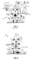
- a very large furnace e.g., a water or air-cooled vertical reactor
- a very large furnace e.g., a water or air-cooled vertical reactor
- the raw material R which can include crushed glass or cullet in powder form
- the combustion gas stream which is traveling upwards, immediately entrains the raw material.
- the suspended glass particles in the high temperature combustion zone soften and, due to surface tension over the glass surface, form into tiny spheres.
- An average size of the resulting glass particles is dictated by the effective terminal velocity (and therefore residence time) of the particle and the average temperature of the surrounding combustion gases. It can be very important to maintain a uniform temperature profile in the furnace gases to produce a required size distribution for the final glass product.
- the final product P is then conveyed along a product discharge path 120 to a sizing process, where proper size product is packed for shipment. In many cases, about 10% to 15% product remains with the furnace exhaust gas passing through flue 106, which requires additional separation process such as cyclonic separation, a bag house, or electrostatic precipitator (ESP), generally designated 114. Cleaned flue gases leave the separator at a stack 118.
- ESP electrostatic precipitator
- the recovered product P R from the bag-house, etc. 114 is typically recycled to the reactor 102 along a path 116.
- the furnace can typically process anywhere from 1000 lb/hr (453.6 kg/hr) to 10,000 lb/hr (4,536 kg/hr) of product, depending on the size.
- the air-fuel burners 112 generally produce a well-mixed bluish flame, which does not have much, if any, visible radiation. This flame also creates outside air infiltration (as shown in Figure 1) A i .
- the ambient air dilution lowers the average flame gas temperature, but increases overall combustion gas volume. This air infiltration causes two effects as far as the process is concerned:
- the furnace reaches a performance bottleneck, where the maximum raw material feed capacity is reached based on furnace diameter, overall length, total burner firing rate, and outside air entrainment. If additional raw material is added, the spherodizing process is negatively affected and the product quality can degrade and becomes an issue.
- the product starts agglomerating in lumps due to poor heat transfer, insufficient entrainment, or due to localized hot-spots in the furnace. Most furnace operators therefore do not exceed furnace production capacity due to quality concerns. A need therefore remains to improve vertical glass furnace production levels while permitting glass quality to be retained.
- a process of operating a vertical glass bead furnace comprises the steps of firing the air-fuel burner and thereby entraining air into the furnace shaft through the open bottom of the shaft, adding raw material into the furnace, and an additional step selected from the group consisting of: (a) injecting oxidant into the shaft adjacent to the shaft bottom using a single lance, (b) operating an oxy-fuel burner in the shaft adjacent to the shaft bottom, (c) injecting oxidant into the shaft adjacent to the shaft bottom using multiple lances, (d) injecting oxidant into the shaft using a lance incorporated into the air-fuel burner, and (e) injecting oxidant into the shaft adjacent to the shaft bottom using an oxidant injection ring.
- a vertical glass furnace comprises a shaft having an interior space and open at the bottom, a raw material addition device mounted so add raw material to the interior of the shaft, an air-fuel burner, and an additional device selected from the group consisting of: (a) a single oxidant injection lance adjacent to the shaft bottom useful for injecting oxidant into the shaft, (b) an oxy-fuel burner in the shaft adjacent to the shaft bottom, (c) multiple oxidant injection lances adjacent to the shaft bottom useful for injecting oxidant into the shaft, (d) a lance incorporated into the air-fuel burner, and (e) an oxidant injection ring positioned for injecting oxidant into the shaft adjacent to the shaft bottom.
- oxygen and oxidant include, but are not limited to: non-pure oxygen, including, but not limited to, oxidants having an oxygen content greater than 21%; oxygen-enriched air; and oxygen-enriched gases wherein the gases are other than pure air.
- One aspect of the present invention relates to several oxygen boost technologies applicable on an air-fuel fired vertical glass furnace for producing spheroidal particles (with glass beads of various sizes).
- the vertical glass furnaces use air-fuel combustion burners to produce hot combustion gasses, which rise up from the bottom of the furnace at temperatures of approximately 2000°F to 3000°F.
- Raw material e.g., glass in powder form
- the temperature of combustion gases is sufficiently above the softening point of the glass to allow surface tension to subsequently spheroidize the particles.
- the glass particles exchange heat energy by conduction (by random collision, fusion with other particles) and through radiation from hot combustion gases.
- the present invention uses an oxidant or oxygen jet at very high velocity from the bottom opening in the furnace.
- This high velocity oxidant or oxygen injection causes an ejector effect and entrains a very large amount of ambient air, up to 100 to 300 times in volume of the injected oxygen, from the bottom opening in the furnace.
- the oxygen enriched air mixes with air-gas burner combustibles to create flame gases at slightly higher temperature. This increase in air-gas flame temperature and additional entrainment of ambient air from the bottom create a faster spheroidization process.
- an oxy-fuel burner is fired upward at the same bottom location as an oxygen lance to create fuel-rich, luminous, and high-temperature oxy-fuel flame.
- the firing rate of the oxy-fuel burner can be adjusted anywhere from about 5 % to 60% of the total furnace firing rate.
- the present invention uses multiple oxygen lances upstream of the air-fuel burner.
- the increased radiation of the (oxy-fuel) flame and subsequent mixing of oxy-fuel products of combustion with air-fuel products of combustion gases increase final gas temperatures.
- the temperature uniformity of the resulting combustion gases results in an increased spheroidization rate and therefore increased productivity. Production increases from 50% to 200% can be achieved over conventional air-fired systems.
- Another aspect of the present invention includes providing a retrofit technology to an air-fuel fired, vertical glass furnace for oxygen firing or boosting to provide additional heat to the process, and thereby enable increased furnace production capacity.
- the additional firing using oxygen is strategically controlled to enable enhanced radiation from the oxygen flame for the spheroidizing process without negative effects on the overall process.
- an increased production from 50% to 200%, depending on the size of the spheres can be achieved while maintaining acceptable product quality.
- Processes in accordance with the present invention can be performed using one or more of a number of methods of oxygen boosting, exemplars of which include the following.
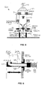
- the oxygen lance 202 is used to inject high velocity oxygen in the center of the vertical furnace 200.
- the lance is made in a shape of a periscope (i.e., approximately 90° angle) for piping convenience, although other similar configurations are also aspects of the present invention.
- the exit nozzle of the lance 202 can have an internal diameter between about 0.5 inches (1.27 cm) and about 2.0 inches (5.08 cm), although those of skill in the art will readily appreciate that either smaller or larger diameters are also usable in the present invention.
- the air-fuel burner flame stoichiometry (equivalence ratio, E) is adjusted such that it is always on the rich side.
- the preferred ratio range is about 0.7 ⁇ E ⁇ 1.00.
- the rich firing generates a large amount of carbon monoxide (CO), unburnt fuel, soot, and other hydrocarbons.
- CO carbon monoxide
- soot soot
- the subsequent combustion of the above products using the oxygen jet J O2 from lance 202 and the entrained ambient air A i creates a very luminous flame.
- the visible flame radiation provides more uniform heat transfer to the glass particles without creating hotspots.
- the location of an oxygen lance 202 can be very important from the overall process point of view.
- the lance is strategically located in the center of the furnace at the bottom.
- the location of the lance is dependent on the oxygen jet penetration into the furnace gas.
- the oxygen jet J O2 is centered and it gradually merges with the products of combustion from air-fuel combustion.
- the gradual mixing provides an increase in flame gas temperature in a uniform fashion.
- the resulting flame gases travel upwards with increased radiative properties.
- the visible radiation of this flame produces additional availability of heat flux for the glass particle spheroidization process. Productivity can improve with the additional radiation.
- One aspect of the present invention includes that the oxygen injection can be performed with a single (e.g., SS-304 stainless steel) lance 202.
- the lance is well-supported underneath the furnace using a support having the flexibility to change injection distance by several feet.
- a particularly preferred injection location is between about 2 feet (0.61 m) to 12 feet (3.66 m) below the air-fuel burners. This is achieved by using a support with an adjustment mechanism in all three (x, y, z) directions.
- the oxygen is preferably injected at a velocity between about 500 ft/s (152.5 m/s) and about 800 ft/s (243.9 m/s).
- the entrainment of ambient air from the bottom and/or sides of the furnace is enhanced by higher reaction rates with oxy combustion.
- the particular configuration of an adjustment mechanism will be readily apparent to one of skill in the art.
- the amount of oxygen injected can be varied to accommodate the operating parameters of the furnace.
- the flow rate can be between about 200 scfh (standard cubic feet per hour) and about 30,000 scfh, depending on the size, overall firing rate, and production rate of the furnace.
- the oxygen proportion injected can be between about 5% and about 30% of the theoretical oxidant needed for the air-fuel burners.
- the oxygen flow is adjusted to either increase or decrease overall flame gas temperatures for a desired bead quality and production rate.
- the air-fuel burners 112, of which there are typically several positioned around the furnace wall, are generally fired at a constant firing rate, whereas the amount of oxygen flow from injection through lance 202 is adjusted to optimize the bead quality.
- the bead quality is generally assessed or expressed by the spherical shape of the product P.
- These beads are generally passed through a rolling sphere test.
- the rolled beads vs. non-spherical (difficult to roll) beads' relative weight percentages are measured to assess bead quality.
- a second test involves measuring the mesh number of the beads using various sieves. The beads are typically made for certain sieve number (40, 60, etc.).
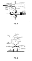
- Another aspect of the present invention involves oxy-fuel burning performed upstream of the air-fuel burners 112, as illustrated in Figure 3.
- the oxy-fuel burner flame F OF stoichiometry (oxidant/fuel ratio, R) is adjusted such that it is always on the rich side.
- the preferred ratio range is 0.5 ⁇ R ⁇ 2.00.
- the rich firing generates a large amount of carbon monoxide (CO), unburnt fuel, soot and other hydrocarbons.
- the subsequent combustion of these products creates a very luminous flame.
- the visible flame radiation provides uniform heat transfer to the glass particles without creating hotspots.
- the location of one or more oxy-fuel burners 302 can also be very important from the overall process point of view.
- the burner is strategically located in the center of the furnace 300 at the bottom, and the location of the burner is dependent on the oxy-fuel flame length.
- the oxy-fuel flame F OF is centered and it gradually merges with the products of combustion from air-fuel combustion.
- the gradual mixing provides an increase in flame gas temperature in a uniform fashion.
- the resulting flame gases travel upwards with increased radiative properties.
- the visible radiation of this flame produces additional availability of heat flux for glass particle spheroidization process.
- the productivity can improve with the additional radiation.
- FIG 4 illustrates an example of an oxy-fuel burner 302 usable in the present invention.
- the burner 302 includes an oxidant inlet 304, a secondary fuel inlet 306, both of which lead to a burner body 308.
- a burner block 310 is connected to an elbow 312 at a flange 314. While the angle of elbow 312 is illustrated to be roughly 90 degrees, those of skill in the art will readily appreciate that it is desirable in some circumstances to direct flame F OF in another direction, for which it may be useful to configure elbow 312 at a different direction, or to mount the burner 302 at a different orientation relative to the vertical axis of the furnace shaft.
- the burner body 308 can be configured to conduct the oxidant and fuel along separate, coaxial flow passages; however, the (unillustrated) flow passages through burner body 308 can also be non-coaxial parallel passages, or other configurations well known to those of skill in the art. Additionally, the oxidant and fuel inlets can be reversed.
- Yet another aspect of the present invention involves multiple oxygen lances upstream of the air-fuel burner(s).
- multiple lances 402 are positioned fluidly before the air-fuel burners in the entrained air stream to inject oxygen streams into the air-fuel burner flame.
- One embodiment of such as oxygen injection system and method 400 is illustrated in Figures 5 and 6.
- the injection method is very specific to distribute oxygen gradually into the flame root (at very low injection velocity, e.g., between about 1 ft/s (0.30 m/s) and about 100 ft/s (30.5 m/s)).
- This relatively low injection velocity is preferably used to prevent immediate mixing of oxygen in the air-fuel flame core and creation of hot spots.
- the gradual oxygen injection allows slower mixing and more uniform subsequent flame gas temperature profile.
- the objective of this oxygen injection is to increase average flame gas temperatures (and heat release rate) for additional glass particle processing.
- the amount of oxygen lancing can be anywhere from about 1000 scfh to 50,000 scfh, depending on the furnace production capacity. The above can result in between 21.5% to 60% enrichment of the combustion air necessary for the air-fuel burners.
- a further aspect of the present invention includes at least one, and preferably multiple lances inserted into the air-fuel burners, as illustrated schematically in Figure 8.
- This injection system 500 and method allows oxygen injection directly into the air-fuel flame F AF to increase its temperature.
- the injection is done into each burner using an oxidant lance 502 to allow a homogeneous oxygen distribution within the flame to avoid hot spots.
- the injection is done at low velocity, e.g., between about 30 ft/s (9.15 m/s) and about 100 ft/s (30.49 m/s), for reasons similar to those presented above.
- Those of skill in the art are well acquainted with various configurations of lances in air-fuel burners, and details thereof will not be included here so as not to obscure the present invention.
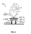
- Yet another aspect of the present invention includes utilization of an oxygen injection ring 602, such as that illustrated in Figure 9, to inject oxygen below the air-fuel flame.
- Oxygen mixes with the air entrained at the bottom of the furnace to participate in combustion.
- the air flowing through the air-fuel burner 112 can be reduced to achieve higher flame temperatures.
- This system and method facilitates the mixing of air with oxygen to generate an homogeneous flame temperature.
- the oxygen injection velocity is preferably between about 30 ft/s (9.15 m/s) and about 200 ft/s (61 m/s).
- the oxidant is supplied to the ring 602 via appropriate supplies 604.
- the injection ring is advantageously positioned at a vertical distance H (see Fig. 7) from the air-fuel burner center axis.
- H is preferably between about 6 inches (15.25 cm) and 36 inches (0.91 m), depending on the size of the furnace 600.
- the outside diameter of the oxygen injection ring 602 should be adjusted to the furnace geometry.
- the ratio D R /D F can be anywhere on the range 0.2 to 0.9, wherein D R is the outer diameter of the oxygen injection ring, and D F is the inner diameter of the furnace shaft 102.
- the oxygen lances and oxy-fuel burner preferably are formed of metallic materials. They have a periscope shape (90° outlet) to reduce exposure of burner parts (such as oxygen and fuel inlets) to thermal radiation and also facilitate burner installation. It is preferably mounted on a structural frame member, so it can be pulled out of the firing or injection position using a simple sliding mechanism.
- the air-fuel burner equivalence ratio is adjusted between about 0.7 and about 1.00 (i.e., fuel-rich), and the remaining oxidant for combustion is supplied through the oxygen lance and entrained ambient air from the bottom of the furnace.
- the oxy-fuel burner firing stoichiometry is adjusted anywhere between about 0.5 and about 2.00 (oxidant/fuel ratio).
- the oxy-fuel burner velocities are adjusted to give a very long, lazy, and luminous flame.
- the oxy-fuel burner products of combustion are allowed to mix with the air-fuel burner products of combustion.
- the resulting mixture has very highly visible radiation and offers higher overall heat transfer to the entrained glass particles.
- the firing of an oxy-fuel burner also increases the amount of entrained air from the bottom of the furnace.
- the overall combustion gas volume is increased to match the increase in flame gas temperature.
- the net effect is higher glass particle entrainment capacity of the furnace gases.
- oxy-fuel burner products of combustion water, CO 2 , CO, soot particles, unburnt fuel, and other hydrocarbons
- a very luminous flame is obtained, in contrast to a bluish or non-luminous flame generated by air-fuel burners.
- the water and CO 2 components due to oxy-fuel firing also offer higher effective heat transfer to the glass particles.
- the single oxygen lance, oxy-fuel burner, or both can be installed anywhere in the furnace shaft from about 2 feet (0.61 m) to 12 feet (3.66 m) below the air-fuel burner.
- the distance between oxygen lance/oxy-fuel burner and air-fuel burner depends on the oxygen injection rate, the oxy-fuel burner firing rate, or both.
- An objective for the single oxygen lance is to create good entrainment of ambient air underneath the furnace and create good mixing with the combustibles from air-fuel burner.
- An objective of the oxy-fuel flame is to minimize excessive penetration into the horizontally fired air-fuel burner flame.
- the oxy-fuel burner can be oxy-gas (e.g., oxygen-natural gas) fired or can be oxygen-fuel oil (e.g. Diesel, bunker-C, etc.) fired, for example, depending on the availability and economics of secondary fuel.
- oxygen-fuel oil e.g. Diesel, bunker-C, etc.
- the resulting flames can be of higher visible radiation compared to oxy-gas firing. This should translate into even higher capacity to process glass particles.
- the oxygen lance aspect of the present invention is followed in a manner which is consistent with oxy-fuel burner firing.
- the lance approach can be utilized simultaneously with the oxy-fuel burner approach.
- An exemplary oxygen lance is illustrated in Figure 6.
- the oxygen lance 402 can be made out of high temperature alloy, refractory material, other similar high temperature material.
- the lance insertion length (L) is adjustable to obtain an optimum radial injection point for appropriate flame temperature development.
- the lance exit 416 has an internal diameter (D) selected to give an average injection velocity between about 1 ft/s (0.3 m/s) and about 100 ft/s (30.5 m/s).
- the oxygen injection velocities are kept lower to delay combustion and prevent any hotspots in the air-fuel flame structure. This is illustrated in Figure 7, where the injected oxygen stream J O2 travels radially outward by riding on the underside of the air-fuel flame F. The oxygen is consumed (by reacting with combustibles in the air-fuel flame) as it travels radially outward. The oxygen jet penetration is prevented by selecting an appropriate nozzle diameter (D). The low velocity oxygen is injected at the air-fuel flame root, and it is immediately dragged towards the flame tip due to air-fuel burner radial momentum. The advantage of low velocity oxygen injection is to delay combustion or allowing a controlled combustion due to the presence of oxygen. The controlled combustion can prevent excessive air-fuel flame temperatures and also uniform flame temperature profile, qualitatively shown in the schematic of Figure 7.
- the vertical height (H) and the lance insertion point (L) are adjusted in consideration of the air-fuel burner firing rate and flame characteristics. As shown in Figure 7, the height (H) can be anywhere from about 6 inches (15.25 cm) to about 36 inches (0.91 m), and the insertion length (L) can be between about 2 inches (5.08 cm) and about 48 inches (1.22 m), depending on the furnace shell internal diameter.
- the oxygen injection can be performed at an axis Y O other than 90° (see Figure 6).
- the injection angle ⁇ can be varied between about 0° and about 80° to suit air-fuel burner flame characteristics, by corresponding changes in the geometry of the lance 402, including elbow 408, or reorientation of the lance relative to the furnace.
- the number of oxygen lances can be same as the number of air-fuel burners according to yet further aspects of the present invention, or it can be higher to suit additional injection of oxygen gas.
- the oxygen can be supplied from an oxygen header or manifold 404, as shown in Figure 5. From the header 404, the oxygen is then uniformly distributed to all individual lances using a flexible hose connection. The flex hose 412 is then connected by a quick disconnect device 410 to install or remove lance from the furnace wall 126.
- Oxygen boosting by lance, burner, or both can be retrofitted into an existing air-fuel fired reaction chamber, including those which are air or water cooled.
Landscapes
- Engineering & Computer Science (AREA)
- Chemical & Material Sciences (AREA)
- Manufacturing & Machinery (AREA)
- Materials Engineering (AREA)
- Organic Chemistry (AREA)
- Glass Melting And Manufacturing (AREA)
- Pre-Mixing And Non-Premixing Gas Burner (AREA)
- Air Supply (AREA)
Applications Claiming Priority (4)
| Application Number | Priority Date | Filing Date | Title |
|---|---|---|---|
| US24465800P | 2000-11-01 | 2000-11-01 | |
| US244658P | 2000-11-01 | ||
| US981740 | 2001-10-19 | ||
| US09/981,740 US6813902B2 (en) | 2000-11-01 | 2001-10-19 | Systems and methods for increasing production of spheroidal glass particles in vertical glass furnaces |
Publications (3)
| Publication Number | Publication Date |
|---|---|
| EP1203754A2 true EP1203754A2 (de) | 2002-05-08 |
| EP1203754A3 EP1203754A3 (de) | 2003-06-04 |
| EP1203754B1 EP1203754B1 (de) | 2006-03-29 |
Family
ID=26936704
Family Applications (1)
| Application Number | Title | Priority Date | Filing Date |
|---|---|---|---|
| EP01402816A Expired - Lifetime EP1203754B1 (de) | 2000-11-01 | 2001-10-30 | Verfahren und Schachtofen zum Herstellen von Glaskugeln |
Country Status (5)
| Country | Link |
|---|---|
| US (1) | US6813902B2 (de) |
| EP (1) | EP1203754B1 (de) |
| JP (1) | JP2002211940A (de) |
| CA (1) | CA2360470C (de) |
| DE (1) | DE60118325D1 (de) |
Cited By (4)
| Publication number | Priority date | Publication date | Assignee | Title |
|---|---|---|---|---|
| RU2223238C1 (ru) * | 2002-08-20 | 2004-02-10 | Открытое акционерное общество "Научно-производственное объединение Стеклопластик" | Устройство для изготовления стеклошариков |
| DE102004003758A1 (de) * | 2004-01-23 | 2005-08-18 | Schott Ag | Glasformkörper und ein Verfahren zu dessen Herstellung |
| WO2009052894A1 (de) * | 2007-10-19 | 2009-04-30 | Deutsche Rockwool Mineralwoll Gmbh & Co.Ohg | Düsenimplantat für kupol- oder schachtöfen |
| EP1537362A4 (de) * | 2002-05-15 | 2012-11-14 | Praxair Technology Inc | Verbrennung mit geringem nox-ausstoss |
Families Citing this family (11)
| Publication number | Priority date | Publication date | Assignee | Title |
|---|---|---|---|---|
| WO2004065849A1 (en) | 2003-01-21 | 2004-08-05 | L'air Liquide - Societe Anonyme A Directoire Et Conseil De Surveillance Pour L'etude Et L'exploitation Des Procedes Georges Claude | Process and apparatus for oxigen enrichment in fuel conveying gases |
| US20070231761A1 (en) * | 2006-04-03 | 2007-10-04 | Lee Rosen | Integration of oxy-fuel and air-fuel combustion |
| US7884055B2 (en) * | 2008-12-04 | 2011-02-08 | Intevep, S.A. | Ceramic microspheres for cementing applications |
| WO2011004851A1 (ja) * | 2009-07-08 | 2011-01-13 | 旭硝子株式会社 | ガラス溶融炉、溶融ガラスの製造方法、ガラス製品の製造装置、及びガラス製品の製造方法 |
| ES2567784T3 (es) * | 2009-11-26 | 2016-04-26 | Linde Ag | Método para calentar una estufa de alto horno |
| US20120214115A1 (en) * | 2011-02-22 | 2012-08-23 | Cameron Andrew M | Method for heating a blast furnace stove |
| US9863013B2 (en) * | 2011-02-22 | 2018-01-09 | Linde Aktiengesellschaft | Apparatus and method for heating a blast furnace stove |
| US20140162204A1 (en) * | 2012-12-11 | 2014-06-12 | Neil G. SIMPSON | Oxy-fuel boosting of zero port area in glass melter using a reversing system |
| CN107056026A (zh) * | 2017-06-13 | 2017-08-18 | 黄尚勇 | 一种能源再利用环保锅炉及其应用 |
| PL3826969T3 (pl) * | 2018-07-26 | 2024-08-19 | Omya International Ag | Puste w środku kuliste cząstki ze szkła |
| BR112022014385A2 (pt) | 2020-01-24 | 2022-09-20 | Basf Se | Processo para preparar partículas de vidro esféricas ocas, e, dispositivo de aquecimento |
Family Cites Families (7)
| Publication number | Priority date | Publication date | Assignee | Title |
|---|---|---|---|---|
| US2619776A (en) * | 1948-03-05 | 1952-12-02 | Rudolf H Potters | Method and apparatus for producing small diameter glass beads |
| BE521556A (de) * | 1953-07-18 | |||
| US2958161A (en) * | 1957-08-13 | 1960-11-01 | Delos M Palmer | Method of melting glass |
| US4046548A (en) * | 1976-04-28 | 1977-09-06 | Potters Industries, Inc. | Apparatus for producing spherical particles |
| GB2178024B (en) * | 1985-07-24 | 1989-08-02 | Glaverbel | Process of and apparatus for producing vitreous beads |
| US5611833A (en) * | 1992-08-26 | 1997-03-18 | Mg Industries | Method and apparatus for producing spheroidal glass particles |
| JPH10212129A (ja) * | 1997-01-23 | 1998-08-11 | Toshiba Glass Co Ltd | ガラスビーズの製造方法 |
-
2001
- 2001-10-19 US US09/981,740 patent/US6813902B2/en not_active Expired - Lifetime
- 2001-10-30 CA CA002360470A patent/CA2360470C/en not_active Expired - Lifetime
- 2001-10-30 EP EP01402816A patent/EP1203754B1/de not_active Expired - Lifetime
- 2001-10-30 DE DE60118325T patent/DE60118325D1/de not_active Expired - Lifetime
- 2001-11-01 JP JP2001336864A patent/JP2002211940A/ja active Pending
Cited By (4)
| Publication number | Priority date | Publication date | Assignee | Title |
|---|---|---|---|---|
| EP1537362A4 (de) * | 2002-05-15 | 2012-11-14 | Praxair Technology Inc | Verbrennung mit geringem nox-ausstoss |
| RU2223238C1 (ru) * | 2002-08-20 | 2004-02-10 | Открытое акционерное общество "Научно-производственное объединение Стеклопластик" | Устройство для изготовления стеклошариков |
| DE102004003758A1 (de) * | 2004-01-23 | 2005-08-18 | Schott Ag | Glasformkörper und ein Verfahren zu dessen Herstellung |
| WO2009052894A1 (de) * | 2007-10-19 | 2009-04-30 | Deutsche Rockwool Mineralwoll Gmbh & Co.Ohg | Düsenimplantat für kupol- oder schachtöfen |
Also Published As
| Publication number | Publication date |
|---|---|
| EP1203754A3 (de) | 2003-06-04 |
| EP1203754B1 (de) | 2006-03-29 |
| CA2360470C (en) | 2010-03-09 |
| CA2360470A1 (en) | 2002-05-01 |
| DE60118325D1 (de) | 2006-05-18 |
| US6813902B2 (en) | 2004-11-09 |
| JP2002211940A (ja) | 2002-07-31 |
| US20020121108A1 (en) | 2002-09-05 |
Similar Documents
| Publication | Publication Date | Title |
|---|---|---|
| EP1203754B1 (de) | Verfahren und Schachtofen zum Herstellen von Glaskugeln | |
| US8272859B2 (en) | Burner for producing inorganic spherical particles | |
| EP2102118B1 (de) | Verfahren und vorrichtung zur herstellung mineralischer fasern | |
| JP4922400B2 (ja) | 無機質球状化粒子製造用バーナ | |
| US8252212B2 (en) | Method for manufacturing inorganic spheroidized particles | |
| JP2002508295A (ja) | ガラス溶融窯の屋根取付け形酸素バーナ及び酸素バーナの使用方法 | |
| EP2051946B1 (de) | Verfahren zur herstellung von mineralfasern | |
| US5447547A (en) | Annular batch feed furnace and process | |
| EP2788294B1 (de) | Verfahren zum recyceln von material bei der herstellung einer mineralschmelze | |
| FI69622C (fi) | Foerfarande och apparat foer framstaellning av glaspaerlor | |
| EP2611744B1 (de) | Verfahren und vorrichtung zur herstellung einer mineralischen schmelze | |
| US9188333B2 (en) | Dilute combustion | |
| JP5074094B2 (ja) | 無機質球状化粒子製造用バーナ | |
| EP1078892A2 (de) | Verfahren und Ofen zum Schmelzen von Glas mittels Sauerstoff-Brennstoff-Brennern | |
| JPH09313918A (ja) | 無機質球状化粒子の製造方法 | |
| JP5887173B2 (ja) | 球状化粒子製造装置及び球状化粒子製造方法 | |
| JPH1192131A (ja) | 無機質球状化粒子の製造方法 |
Legal Events
| Date | Code | Title | Description |
|---|---|---|---|
| PUAI | Public reference made under article 153(3) epc to a published international application that has entered the european phase |
Free format text: ORIGINAL CODE: 0009012 |
|
| AK | Designated contracting states |
Kind code of ref document: A2 Designated state(s): AT BE CH CY DE DK ES FI FR GB GR IE IT LI LU MC NL PT SE TR |
|
| AX | Request for extension of the european patent |
Free format text: AL;LT;LV;MK;RO;SI |
|
| PUAL | Search report despatched |
Free format text: ORIGINAL CODE: 0009013 |
|
| AK | Designated contracting states |
Designated state(s): AT BE CH CY DE DK ES FI FR GB GR IE IT LI LU MC NL PT SE TR |
|
| AX | Request for extension of the european patent |
Extension state: AL LT LV MK RO SI |
|
| 17P | Request for examination filed |
Effective date: 20031204 |
|
| AKX | Designation fees paid |
Designated state(s): BE DE ES FR GB IT |
|
| 17Q | First examination report despatched |
Effective date: 20040701 |
|
| GRAP | Despatch of communication of intention to grant a patent |
Free format text: ORIGINAL CODE: EPIDOSNIGR1 |
|
| GRAS | Grant fee paid |
Free format text: ORIGINAL CODE: EPIDOSNIGR3 |
|
| GRAA | (expected) grant |
Free format text: ORIGINAL CODE: 0009210 |
|
| AK | Designated contracting states |
Kind code of ref document: B1 Designated state(s): BE DE ES FR GB IT |
|
| PG25 | Lapsed in a contracting state [announced via postgrant information from national office to epo] |
Ref country code: IT Free format text: LAPSE BECAUSE OF FAILURE TO SUBMIT A TRANSLATION OF THE DESCRIPTION OR TO PAY THE FEE WITHIN THE PRESCRIBED TIME-LIMIT;WARNING: LAPSES OF ITALIAN PATENTS WITH EFFECTIVE DATE BEFORE 2007 MAY HAVE OCCURRED AT ANY TIME BEFORE 2007. THE CORRECT EFFECTIVE DATE MAY BE DIFFERENT FROM THE ONE RECORDED. Effective date: 20060329 |
|
| REG | Reference to a national code |
Ref country code: GB Ref legal event code: FG4D |
|
| REF | Corresponds to: |
Ref document number: 60118325 Country of ref document: DE Date of ref document: 20060518 Kind code of ref document: P |
|
| PG25 | Lapsed in a contracting state [announced via postgrant information from national office to epo] |
Ref country code: DE Free format text: LAPSE BECAUSE OF FAILURE TO SUBMIT A TRANSLATION OF THE DESCRIPTION OR TO PAY THE FEE WITHIN THE PRESCRIBED TIME-LIMIT Effective date: 20060630 |
|
| PG25 | Lapsed in a contracting state [announced via postgrant information from national office to epo] |
Ref country code: ES Free format text: LAPSE BECAUSE OF FAILURE TO SUBMIT A TRANSLATION OF THE DESCRIPTION OR TO PAY THE FEE WITHIN THE PRESCRIBED TIME-LIMIT Effective date: 20060710 |
|
| ET | Fr: translation filed | ||
| PLBE | No opposition filed within time limit |
Free format text: ORIGINAL CODE: 0009261 |
|
| STAA | Information on the status of an ep patent application or granted ep patent |
Free format text: STATUS: NO OPPOSITION FILED WITHIN TIME LIMIT |
|
| 26N | No opposition filed |
Effective date: 20070102 |
|
| GBPC | Gb: european patent ceased through non-payment of renewal fee |
Effective date: 20061030 |
|
| PG25 | Lapsed in a contracting state [announced via postgrant information from national office to epo] |
Ref country code: GB Free format text: LAPSE BECAUSE OF NON-PAYMENT OF DUE FEES Effective date: 20061030 |
|
| REG | Reference to a national code |
Ref country code: FR Ref legal event code: PLFP Year of fee payment: 15 |
|
| REG | Reference to a national code |
Ref country code: FR Ref legal event code: PLFP Year of fee payment: 16 |
|
| PGFP | Annual fee paid to national office [announced via postgrant information from national office to epo] |
Ref country code: FR Payment date: 20161020 Year of fee payment: 16 |
|
| PGFP | Annual fee paid to national office [announced via postgrant information from national office to epo] |
Ref country code: BE Payment date: 20161019 Year of fee payment: 16 |
|
| REG | Reference to a national code |
Ref country code: FR Ref legal event code: ST Effective date: 20180629 |
|
| REG | Reference to a national code |
Ref country code: BE Ref legal event code: MM Effective date: 20171031 |
|
| PG25 | Lapsed in a contracting state [announced via postgrant information from national office to epo] |
Ref country code: FR Free format text: LAPSE BECAUSE OF NON-PAYMENT OF DUE FEES Effective date: 20171031 Ref country code: BE Free format text: LAPSE BECAUSE OF NON-PAYMENT OF DUE FEES Effective date: 20171031 |