EP1203852A2 - Handlauf - Google Patents
Handlauf Download PDFInfo
- Publication number
- EP1203852A2 EP1203852A2 EP01125979A EP01125979A EP1203852A2 EP 1203852 A2 EP1203852 A2 EP 1203852A2 EP 01125979 A EP01125979 A EP 01125979A EP 01125979 A EP01125979 A EP 01125979A EP 1203852 A2 EP1203852 A2 EP 1203852A2
- Authority
- EP
- European Patent Office
- Prior art keywords
- handrail
- generally
- stairway
- disposed portions
- assembly
- Prior art date
- Legal status (The legal status is an assumption and is not a legal conclusion. Google has not performed a legal analysis and makes no representation as to the accuracy of the status listed.)
- Granted
Links
Images






Classifications
-
- A—HUMAN NECESSITIES
- A47—FURNITURE; DOMESTIC ARTICLES OR APPLIANCES; COFFEE MILLS; SPICE MILLS; SUCTION CLEANERS IN GENERAL
- A47K—SANITARY EQUIPMENT; ACCESSORIES THEREFOR, e.g. TOILET ACCESSORIES
- A47K17/00—Other sanitary equipment not covered by the other groups of this subclass ; Holders for toilet brushes
- A47K17/02—Body supports, other than seats, for closets, e.g. handles, back-rests, foot-rests; Accessories for closets, e.g. reading tables
- A47K17/026—Armrests mounted on or around the toilet
-
- A—HUMAN NECESSITIES
- A47—FURNITURE; DOMESTIC ARTICLES OR APPLIANCES; COFFEE MILLS; SPICE MILLS; SUCTION CLEANERS IN GENERAL
- A47K—SANITARY EQUIPMENT; ACCESSORIES THEREFOR, e.g. TOILET ACCESSORIES
- A47K17/00—Other sanitary equipment not covered by the other groups of this subclass ; Holders for toilet brushes
- A47K17/02—Body supports, other than seats, for closets, e.g. handles, back-rests, foot-rests; Accessories for closets, e.g. reading tables
- A47K17/022—Wall mounted grab bars or handles, with or without support on the floor
-
- B—PERFORMING OPERATIONS; TRANSPORTING
- B60—VEHICLES IN GENERAL
- B60N—SEATS SPECIALLY ADAPTED FOR VEHICLES; VEHICLE PASSENGER ACCOMMODATION NOT OTHERWISE PROVIDED FOR
- B60N3/00—Arrangements or adaptations of other passenger fittings, not otherwise provided for
- B60N3/02—Arrangements or adaptations of other passenger fittings, not otherwise provided for of hand grips or straps
-
- E—FIXED CONSTRUCTIONS
- E04—BUILDING
- E04F—FINISHING WORK ON BUILDINGS, e.g. STAIRS, FLOORS
- E04F11/00—Stairways, ramps, or like structures; Balustrades; Handrails
- E04F11/18—Balustrades; Handrails
- E04F11/1863—Built-in aids for ascending or descending stairs
Definitions
- the present invention relates to ergonomic handrails and, more particularly, to a handrail having a generally wavy shape that enables infirm persons such as elderly and disabled persons to grasp it readily and firmly without causing their hands to accidentally slip from grasping engagement therewith.
- the invention also relates to a handrail assembly for assisting a person when sitting or standing relative to a fixed structure such as a toilet or a bathtub.
- a handrail extending along a wall or a stairway to facilitate the movement of persons therealong.
- facilities such as hospitals, nursing homes and private homes for elderly or disabled persons make extensive use of handrails so that infirm persons can grasp them for support when moving around or for assistance when lifting themselves onto or from a toilet.
- Such a handrail is particularly helpful to them in a bathroom in supporting themselves during bathing and getting in and out of the tub.
- handrails comprise a length of solid or tubular material which is generally straight or L-shaped.
- a handrail is generally supported on a wall by conventional supports so that it extends obliquely along a stairway.
- users usually reach downward to grasp onto the handrail by bending their wrist forwardly. This forward bending movement of the wrist tends to prevent the users from gripping the handrail firmly thus increasing the risk of accidental slippage of their hands from grasping engagement therewith.
- Handrails disposed in bathrooms, toilets, foyers or the like generally include vertically extending sections which users grasp for support during sitting down or standing up. When the user lifts oneself onto or from a toilet, he or she grasps and holds onto the vertical section and then stretches or bends both arms gradually so that he or she can move toward or from the toilet seat.
- the disadvantage with such handrails is that infirm persons must be strong enough to pull themselves up and support their own weight during sitting down on or standing up from the toilet seat. Handrails will not help such infirm persons who are too weak or incapacitated.
- a handrail assembly comprising: a handrail having a generally wavy shape, the handrail comprising an alternating combination of generally upwardly curved sections and generally downwardly curved sections; and means for mounting the handrail relative to a structure so that it is readily engaged by the hand of a user.
- the handrail assembly may further comprise a plurality of generally straight sections each interposed between two adjacent, generally upwardly and downwardly curved sections, the axes of two adjacent ones of said generally straight sections intersecting with each other at an obtuse angle.
- the handrail assembly may further comprise at least one straight section disposed near one end thereof.
- a handrail assembly adapted for use with a stairway, comprising: a handrail having a generally wavy shape; and means for mounting the handrail obliquely along a stairway to provide an alternating combination of generally horizontally disposed portions and generally vertically disposed portions, the generally vertically disposed portions being adapted to be grasped by a user without bending his or her wrist forwardly in ascending a flight of stairs, the generally horizontally disposed portions being adapted to be grasped by a user without bending his or her wrist forwardly in descending the flight of stairs.
- the handrail is mounted relative to the stairway so that each of the generally horizontally and vertically disposed portions is disposed generally above a step and a riser of the stairway, respectively.
- the generally horizontally disposed portions of the handrail may have a width greater than the generally vertically disposed portions so that the user can grasp and lean on the generally horizontally disposed portions for support in descending the flight of stairs.
- the handrail includes an anti-slip means provided thereon which comprises a plurality of grooves extending longitudinally thereof.
- the handrail may include indicia thereon for aiding a visually handicapped person in moving up and down the stairway, and the indicia are in the braille system, including characters to be felt and distinguished by human fingers.
- a handrail assembly adapted for use in a mass transit system, comprising: a handrail having a generally wavy shape; the handrail comprising an alternating combination of generally upwardly and downwardly curved sections; means for rigidly mounting the handrail generally horizontally below a ceiling of a car of a mass transit system; a plurality of flexible straps depending from the handrail; and a plurality of grip rings movably connected to the lower ends of the plurality of flexible straps, the handrail and the grip rings being adapted to be grasped by passengers in keeping a standing position in a moving mass transit system.
- the plurality of flexible straps are of equal length and have their upper ends secured to the handrail at the upwardly and downwardly curved sections thereof to provide the grip rings at two different levels.
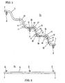
- a handrail assembly as generally designated at T1, includes a handrail 1, conventional supports 2, and caps 3 mounted at both ends of the handrail 1.
- the handrail 1 comprises an elongated, solid body made of hard plastic material having a generally circular cross section. It should be understood that the handrail may be fabricated from a hollow pipe made of certain metal. It should be noted that, as best shown in FIGs. 1 and 3, the handrail 1 has a wavy, or generally sinusoidal, shape for reasons to be fully described later.
- the wavy-shaped handrail 1 comprises a repetitive occurrence of three different sections, i.e., a upwardly curved section 10, a downwardly curved section 11, and a generally straight section 12 of a predetermined length interposed between two adjacent, upwardly and downwardly curved sections 10, 11, Virtual boundaries between the upwardly or downwardly curved sections 10, 11 and the interposed, generally straight section 12 are generally indicated by broken lines extending perpendicular to the handrail 1 at those boundaries. It should be noted that virtual axes 1 ⁇ , 2 ⁇ , 3 ⁇ , 4 ⁇ extending through two adjacent ones of the generally straight sections 12 intersect with each other at an obtuse angle 13.
- the handrail 1 has a diameter of approximately 34 mm and the radius of curvature of the upwardly and downwardly curved sections 10 and 11 is approximately 100 mm.
- the length of the generally straight section 12 is approximately 93 mm and two adjacent ones of the generally straight sections 12 intersect with each other at an angle of approximately 100 degrees. Also, the total length of the handrail 1 as measured between both ends is approximately 1500 mm.
- the handrail assembly T1 is shown as mounted on a wall 5 by three conventional supports 2 relative to a stairway 4.
- the handrail 1 as a whole, extends obliquely along the stairway 4 so that each generally horizontally disposed portion A and each generally vertically disposed portion B both consisting of the generally straight sections 12 and portions of their adjacent curved sections 10 and 11 are disposed generally above a step 40 and a riser 41 between two adjacent steps 40, respectively.
- the relative level of the handrail 1 and the stairway 4 may vary depending upon the average height of users and, it is preferable to mount the handrail at a level corresponding to the user's waist portion.
- the user in ascending a flight of stairs, can first grasp the generally vertically disposed portion B of the handrail 1 more firmly and smoothly than a conventional straight handrail without bending or cocking his or her wrist forwardly, because the handrail 1 is more vertical than the conventional one. Then, the user can grasp and lean on the generally horizontally disposed portion A of the handrail 1, because the portion A has much less slope than the conventional handrail.
- the wavy shaped handrail 1 is best suited to infirm persons such as elderly or disabled persons in that, during ascending, they can grasp the vertically and horizontally disposed portions B and A firmly with a reduced risk of accidental slippage of their hands from gripping engagement with the handrail. Gripping the generally vertically disposed portions B and then the generally horizontally disposed portions A will enable such persons to pull themselves up and then support their own weight.
- the generally straight sections 12 are generally easier to grip than the upwardly and downwardly curved portions 10 and 11. Accordingly, it should be readily understood that the user is recommended to grasp the generally straight section 12 of the generally vertically disposed portions B during ascending and the generally straight section 12 of the generally horizontally disposed portions A during descending because to do so will reduce the risk of accidental slippage of his or her hands from gripping engagement with the handrail.
- the axes of two adjacent ones of the generally straight sections 12 are arranged to intersect with each other at an obtuse angle 13 of 100 degrees, for example, so that a relatively smooth transition occurs between the generally horizontally and vertically disposed portions A and B. This will enable the user to slide his or her hands from one to the other of the portions A and B without substantially detaching from the handrail.
- the generally horizontally and vertically disposed portions A and B are arranged in relation to the stairway 4 such that the portions A and B are disposed generally above the steps 40 and the risers 41 therebetween, respectively, This will permit the user to readily grasp the portions A and B depending upon whether he or she is descending or ascending a flight of stairs.
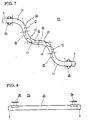
- the handrail assembly T2 which includes a handrail 1a mounted on a wall by conventional supports 2 for a stairway 4.
- the handrail assembly T2 includes five supports 2 mouated to the generally straight portions 12 of the handrail 1a at an equal spacing from each other.
- the handrail 1a has a diameter of approximately 34 mm and the radius of curvature of the upwardly and downwardly curved sections 10 and 11 is approximately 100 mm.
- the length of the generally straight sections 12 is approximately 130 mm and two adjacent ones of the generally straight sections 12 intersect each other at an angle 13 of approximately 105 degrees.
- the total length of the handrail 1a as measured between both ends is approximately 4000 mm.
- the handrail 1a of the invention it is preferable to mount the handrail 1a of the invention relative to a stairway 4 such that the generally horizontally disposed portions A and the generally vertically disposed portions B are positioned generally above the steps 40 and the risers 41, respectively.
- the present invention is not limited to such relative positioning of the handrail and the stairway.
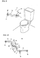
- FIGs. 7 to 9 there is illustrated a third embodiment of the present invention T3 which includes a handrail 1b mounted on a wall 5 by conventional supports 2b in a toilet.
- the handrail 1b is generally wavy-shaped, including two generally upwardly curved sections 10 and two generally downwardly curved sections 11. However, it does not include a plurality of generally straight sections 12 as is the case with the handrails 1 and 1a as shown in FIGs. 1 to 6.
- the handrail 1b is also provided with caps 3 at both ends.
- the handrail tb has a diameter of approximately 34 mm and the radius of curvature of the upwardly and downwardly curved sections 10 and 11 is approximately 100 mm. Two adjacent ones of the generally straight sections 12 intersect with each other at an angle 13 of approximately 95 degrees. Also, the total length of the handrail 1b as measured between both ends is approximately 600 mm.
- the handrail 1b is mounted generally obliquely on the wall 5 by conventional supports 2c so as to provide an alternating combination of generally horizontally and vertically disposed portions which comprise the generally downwardly and upwardly curved sections and transition sections therebetween.
- the user In lifting oneself onto the toilet, the user will grasp either the generally vertically or horizontally portions of the handrail 1b for support and gradually slide his or her hand downwardly along the handrail while supporting his or her own weight. By so doing, the user does not have to stretch his or her arm. This will also enable the user to maintain his or her grip on the handrail during sliding so that the risk of injury by the user falling onto the toilet will be greatly reduced.
- the user may well grasp either the generally horizontally or vertically portions of the handrail 1b located at a position easier to grasp, and then pull oneself up and support his or her own weight.
- the curvature of the curved portions 10, 11 serves to prevent accidental slippage of the user's hand leading to injury due to falling onto the toilet.
- the handrail 1b is shown as mounted obliquely with respect to the toilet floor, the present invention is not limited to such mounting of the handrail and that it can be mounted generally parallel or perpendicular to the toilet floor.
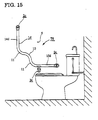
- the handrail 1c additionally includes two straight sections 14c and 15c disposed near both ends of the handraillc. Both of the straight sections 14c, 15c are generally parallel not only to each other but also to the toilet floor,
- the handrail 1c is mounted on a wall 5 obliquely with the straight section 15c located just by the side of the toilet seat so that it can be readily engaged by the hand of the user.
- a conventional cap 3 is mounted at each end of the handrail 1c.
- a generally straight section 12 is not provided between two adjacent, generally upwardly and downwardly curved sections 10 and 11 unlike the first and second embodiments of the invention.
- the handrail 1c has a diameter of approximately 32 mm and the radius of curvature of the upwardly and downwardly curved sections 10 and 11 is approximately 110 mm.
- the lengths of the straight sections 14c and 15c are approximately 100 and 300 mm, respectively,
- the handrail 1d includes two straight sections 14d and 15d disposed near both ends thereof These straight sections 14d, 15d are disposed generally vertically and horizontally, respectively. Unlike the first and second embodiments of the invention, such a generally straight section 12 is not provided between two adjacent, generally upwardly and downwardly curved sections 10 and 11.
- the handrail 1d has a diameter of approximately 32 mm and the radius of curvature of the upwardly and downwardly curved sections 10 and 11 is approximately 110 mm.
- the length of the straight sections 14d and 15d is approximately 300 mm,
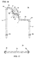
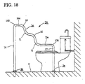
- FIGs. 16 to 18 there is illustrated a sixth embodiment of the invention T6 which is adapted for use in a toilet or bathtub.
- the handrail assembly T6 differs from that T4 as shown in FIGs. 10 to 12 in that the handrail 1e is mounted on a floor 6 rather than on a wall.
- the handrail 1e additionally includes vertically disposed, post sections 16 and 17 whose lower ends are mounted on the floor by conventional mounting members 2e.
- the handrail 1e has a diameter of approximately 34 mm and the radius of curvature of the upwardly and downwardly curved sections 10 and 11 is approximately 110 mm.
- the lengths of the horizontally disposed, straight sections 14e and 15e are approximately 150 and 300 mm, respectively.
- the vertically disposed post sections 16 and 17 are approximately 800 and 600 mm, respectively.
- the radius of curvature of generally upwardly curved sections 160 and 170 located between the straight sections 14e, 15e and the post sections 16, 17 is approximately 35 mm.
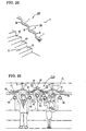
- FIGs. 19 to 20 there is illustrated a seventh embodiment of the invention T7 which is adapted for use with a stairway 4, As depicted, the handrail assembly T7 is different from that T1 as shown in FIG. 3 in the inclusion of an anti-slip mechanism 18.
- This anti-slip mechanism 18 serves to prevent accidental slippage of user's hands from grasping engagement with a handrail If during ascending and descending.
- the anti-slip mechanism 18 may be in the form of grooves 180 formed in the upper half circumference of the handrail If and extending longitudinally thereof, as shown in FIG. 20. Alternatively, the grooves may be formed to extend circumferentially of the handrail.
- Other forms of anti-slip mechanisms may be provided using, for example, anti-slip pads adhered to the handrail or material having an inherent anti-slip or frictional property. With this anti-slip mechanism used, the user can safely ascend or descend a flight of stairs by firmly grasping the handrail.
- FIG. 21 there is illustrated an eighth embodiment of the invention T8 which is adapted for use with a stairway 4.
- the handrail assembly T8 as shown differs from that T7 as shown in FIG. 19 in the provision of indicia 190a, 190b, 191a and 191b on the handrail 1g for aiding a visually handicapped person in moving up and down stairs.
- the indicia 190a, 190b, 191a and 191b are in the braille system and include characters to be felt and distinguished by human fingers. As shown, these indicia are disposed on the upper side of the handrail 1g. Alternatively, the indicia may be disposed on the lower side of the handrail so that when a visually handicapped person manually grips the handrail, their fingers will be wrapped around the lower side of the handrail and will engage the characters of the indicia for manual reading.
- indicia 190a and 190b disposed on the generally vertically and horizontally disposed portions B and A of the handrail 1g, respectively, and also indicia 191a and 191b associated with the first or lower step and the last or top step of the stairway 4, respectively.
- the indicium 191a may include characters indicating the numeral 1 or the number of steps to go before reaching the top of the flight of stairs.
- the indicium 191b may include characters indicating the numeral corresponding to the top of the flight of stairs or the number of steps to go before reaching the bottom of the stairway.
- Each indicium 190a which is disposed on a generally vertically disposed portion B, may include characters setting forth the number corresponding to the step associated with the portion B or the number of steps to go before reaching the top of the flight of stairs.
- each indicium 190b which is disposed on a generally horizontally disposed portion A, may include characters indicating the number corresponding to the step associated with the portion A or the number of steps to go before reaching the bottom of the flight of stairs.
- the indicia 190a, 190b, 191a and 191b may include characters setting forth the nature or appearance of the top or bottom floor of the stairway.
- the indicia 190a, 190b, 191a and 191b could be provided on the handrail in a variety of ways, it may be preferred to form the indicia on a metal strip or bar with the characters projecting from the base.
- the metal strip or base may be secured to the handrail 1g with a suitable adhesive or other type of fastener so as to conform to the contour of the handrail.
- a visually handicapped person having knowledge of the braille system, can distinguish the characters to determine the number of steps in a flight of stairs and/or the location of a step in the flight of stairs.
- the handrail 1h includes an alternating combination of generally horizontally disposed sections 7 and generally vertically disposed sections 8 wherein the former sections 7 have a lateral dimension greater than the latter sections 8.
- the former or generally horizontally disposed sections 7 are generally oblong in cross section and have a wider upper surface so that the user can temporalily lean on it by his or her elbow for support in ascending or descending the flight of stairs. This will aid infirm persons such as elderly or disabled persons in ascending or descending the flight of stairs.
- the handrail assembly T10 which is adapted for use with a mass transmit system such as a commuter train, a bus, a subway, a street car or the like.
- the handrail assembly T10 includes a wavy-shaped handrail 1i mounted generally horizontally below a ceiling of a car of a commuter train.
- a plurality of depending support posts 9 are used to rigidly mount the handrail 1i relative to the car structure.
- Each support post 9 has its upper end fixed to the ceiling and its lower end secured to upwardly curved sections 10 of the handrail 1i.
- the handrail assembly T10 also includes a plurality of flexible straps 91 depending from the handrail 1i that assists passengers in keeping a standing position in the moving car. As shown, all of the straps 91 have their lower ends connected to grip rings 90 to enable the passengers to grip them readily. The straps 91 have their upper ends secured to either the upper or downwardly curved sections 10,11. Since the straps 91 are of equal length, the grip rings 90 are at two different levels depending upon the location of the straps along the handrail 1i. This will provide flexibility to passengers in selecting which straps they should use in keeping themselves in a standing position.
- the handrail 1i has a diameter of approximately 34 mm and the radius of curvature of the upwardly and downwardly curved sections 10, 11 is approximately 350 mm.
Landscapes
- Public Health (AREA)
- Health & Medical Sciences (AREA)
- Engineering & Computer Science (AREA)
- Epidemiology (AREA)
- Architecture (AREA)
- General Health & Medical Sciences (AREA)
- Civil Engineering (AREA)
- Transportation (AREA)
- Structural Engineering (AREA)
- Mechanical Engineering (AREA)
- Steps, Ramps, And Handrails (AREA)
- Toilet Supplies (AREA)
- Bathtubs, Showers, And Their Attachments (AREA)
- Ladders (AREA)
- Devices For Conveying Motion By Means Of Endless Flexible Members (AREA)
Priority Applications (2)
| Application Number | Priority Date | Filing Date | Title |
|---|---|---|---|
| EP06011807A EP1693529A3 (de) | 2000-11-02 | 2001-10-31 | Handlauf |
| CY20081100484T CY1107936T1 (el) | 2000-11-02 | 2008-05-08 | Χειρολισθηρας |
Applications Claiming Priority (4)
| Application Number | Priority Date | Filing Date | Title |
|---|---|---|---|
| JP2000336777 | 2000-11-02 | ||
| JP2000336777 | 2000-11-02 | ||
| JP2001318680A JP3660292B2 (ja) | 2000-11-02 | 2001-10-16 | 手すり及び手すりの取付構造 |
| JP2001318680 | 2001-10-16 |
Related Child Applications (1)
| Application Number | Title | Priority Date | Filing Date |
|---|---|---|---|
| EP06011807A Division EP1693529A3 (de) | 2000-11-02 | 2001-10-31 | Handlauf |
Publications (3)
| Publication Number | Publication Date |
|---|---|
| EP1203852A2 true EP1203852A2 (de) | 2002-05-08 |
| EP1203852A3 EP1203852A3 (de) | 2003-09-17 |
| EP1203852B1 EP1203852B1 (de) | 2008-02-13 |
Family
ID=26603394
Family Applications (2)
| Application Number | Title | Priority Date | Filing Date |
|---|---|---|---|
| EP06011807A Withdrawn EP1693529A3 (de) | 2000-11-02 | 2001-10-31 | Handlauf |
| EP01125979A Expired - Lifetime EP1203852B1 (de) | 2000-11-02 | 2001-10-31 | Handlauf |
Family Applications Before (1)
| Application Number | Title | Priority Date | Filing Date |
|---|---|---|---|
| EP06011807A Withdrawn EP1693529A3 (de) | 2000-11-02 | 2001-10-31 | Handlauf |
Country Status (9)
| Country | Link |
|---|---|
| US (1) | US6857622B2 (de) |
| EP (2) | EP1693529A3 (de) |
| JP (1) | JP3660292B2 (de) |
| AT (1) | ATE386176T1 (de) |
| CY (1) | CY1107936T1 (de) |
| DE (1) | DE60132745T2 (de) |
| DK (1) | DK1203852T3 (de) |
| ES (1) | ES2301511T3 (de) |
| PT (1) | PT1203852E (de) |
Cited By (4)
| Publication number | Priority date | Publication date | Assignee | Title |
|---|---|---|---|---|
| US20150048205A1 (en) * | 2013-08-14 | 2015-02-19 | Airbus Operations Gmbh | Multifunctional support rail |
| CN105151975A (zh) * | 2015-09-21 | 2015-12-16 | 胡刚 | 一种设有悬挂扶手的滚梯 |
| US20160166118A1 (en) * | 2014-12-16 | 2016-06-16 | Kohler Co. | Shower storage and assist assembly |
| FR3032931A1 (fr) * | 2015-02-25 | 2016-08-26 | Sncf Mobilites | Garde-corps pour escalier d'un vehicule de transport |
Families Citing this family (22)
| Publication number | Priority date | Publication date | Assignee | Title |
|---|---|---|---|---|
| US8522487B2 (en) | 2008-08-06 | 2013-09-03 | SafePro, L.P. | Safety hatch system and egress |
| US8726577B2 (en) * | 2009-06-26 | 2014-05-20 | SafePro, L.P. | Integrated safety rail protection system |
| JP6064295B2 (ja) * | 2011-01-17 | 2017-01-25 | Toto株式会社 | トイレ用手すり |
| JP2012210858A (ja) * | 2011-03-31 | 2012-11-01 | Tcm Corp | 産業車両の手摺構造 |
| JP5294350B2 (ja) * | 2011-03-31 | 2013-09-18 | 独立行政法人国立高等専門学校機構 | 手すり |
| USD690575S1 (en) | 2012-02-06 | 2013-10-01 | Donna Raye Stark | Handrail |
| US20140097394A1 (en) * | 2012-10-09 | 2014-04-10 | Ming-Fang Hsieh | Handrail Assembly |
| JP2014127021A (ja) * | 2012-12-26 | 2014-07-07 | Qunetto International | 避難路用手すりとこの手すりを備えた避難路 |
| USD713545S1 (en) | 2013-03-18 | 2014-09-16 | Qunetto East Co., Ltd. | Handrail |
| USD713543S1 (en) | 2013-03-18 | 2014-09-16 | Qunetto East Co., Ltd. | Handrail |
| USD713544S1 (en) | 2013-03-18 | 2014-09-16 | Qunetto East Co., Ltd. | Handrail |
| JP6205245B2 (ja) * | 2013-11-01 | 2017-09-27 | 株式会社クネット・インターナショナル | 波状手すり形成装置 |
| JP2015194044A (ja) * | 2014-03-31 | 2015-11-05 | ナカ工業株式会社 | 手摺笠木 |
| DE102015215780A1 (de) * | 2015-08-19 | 2017-02-23 | Siemens Aktiengesellschaft | Haptische Haltestangenabdeckung |
| CN106080328A (zh) * | 2016-06-21 | 2016-11-09 | 深圳市中科思达青少年科学探索研究中心 | 一种公共交通扶手 |
| JP2020139306A (ja) * | 2019-02-27 | 2020-09-03 | 株式会社カワノ | 手摺りの接続機構 |
| JP7124800B2 (ja) | 2019-07-09 | 2022-08-24 | トヨタ自動車株式会社 | バス用手すり及びバス車内構造 |
| JP2021055272A (ja) * | 2019-09-27 | 2021-04-08 | 山崎産業株式会社 | 手摺装置 |
| CN111445650B (zh) * | 2020-05-07 | 2020-12-25 | 江苏伟创硅业科技有限公司 | 一种老人如厕用安全保护指示灯 |
| US11700982B2 (en) * | 2020-08-27 | 2023-07-18 | M-Power Bar, LLC | Ergonomic grab bar |
| JP2023032178A (ja) * | 2021-08-26 | 2023-03-09 | 株式会社東海技研工業 | 介護用具 |
| JP7012192B1 (ja) | 2021-10-15 | 2022-01-27 | 潤一郎 尾島 | 歩行手すり |
Family Cites Families (14)
| Publication number | Priority date | Publication date | Assignee | Title |
|---|---|---|---|---|
| US4243207A (en) * | 1978-11-20 | 1981-01-06 | Lambertus Heykants | Free standing portable stairway railing device |
| JPS56150264A (en) * | 1980-04-21 | 1981-11-20 | Naka Tech Lab | Handrail coping |
| GB2147928B (en) * | 1983-10-14 | 1986-09-17 | Trent Valley Engineering | Handrails |
| DE3406944A1 (de) * | 1984-02-25 | 1985-08-29 | Riedel Erich O Dipl Ing | Therapierohr |
| US4557467A (en) * | 1984-08-14 | 1985-12-10 | Lin Ta C | Elbow of staircase hand rail |
| EP0182308B1 (de) * | 1984-11-19 | 1990-05-23 | Hans Grimberg Edelstahl GmbH | Sicherheitsgriffsystem |
| DE9015002U1 (de) * | 1990-10-31 | 1991-01-10 | Eisen- Und Drahtwerk Erlau Ag, 7080 Aalen | Bausatz zum Herstellen von Griffen, Handläufen, Abschrankungen, Kleinmöbeln und dgl. |
| US5065837A (en) * | 1991-02-05 | 1991-11-19 | Szudy Katherine A | Handrail for aiding visually handicapped |
| DE4121992A1 (de) * | 1991-07-03 | 1993-01-07 | Heidelberger Druckmasch Ag | Absturzsicherung an einem podest einer druckmaschine |
| GB9520000D0 (en) * | 1995-09-30 | 1995-12-06 | Gamwell Douglas F | Improvements in or relating to passenger supports |
| USD378432S (en) * | 1995-10-24 | 1997-03-11 | Coco Raynes | Handrail with a braille insert |
| JP2000043720A (ja) * | 1998-07-30 | 2000-02-15 | Hitachi Ltd | 車両の吊り手 |
| US6533251B1 (en) * | 1999-01-20 | 2003-03-18 | Michael Abbaticchio | Modular railing system |
| JP2000303647A (ja) * | 1999-04-23 | 2000-10-31 | Sekisui House Ltd | 立ち座り手摺 |
-
2001
- 2001-10-16 JP JP2001318680A patent/JP3660292B2/ja not_active Expired - Lifetime
- 2001-10-31 AT AT01125979T patent/ATE386176T1/de active
- 2001-10-31 DE DE60132745T patent/DE60132745T2/de not_active Expired - Lifetime
- 2001-10-31 DK DK01125979T patent/DK1203852T3/da active
- 2001-10-31 EP EP06011807A patent/EP1693529A3/de not_active Withdrawn
- 2001-10-31 PT PT01125979T patent/PT1203852E/pt unknown
- 2001-10-31 EP EP01125979A patent/EP1203852B1/de not_active Expired - Lifetime
- 2001-10-31 ES ES01125979T patent/ES2301511T3/es not_active Expired - Lifetime
- 2001-11-01 US US10/004,541 patent/US6857622B2/en not_active Expired - Fee Related
-
2008
- 2008-05-08 CY CY20081100484T patent/CY1107936T1/el unknown
Cited By (6)
| Publication number | Priority date | Publication date | Assignee | Title |
|---|---|---|---|---|
| US20150048205A1 (en) * | 2013-08-14 | 2015-02-19 | Airbus Operations Gmbh | Multifunctional support rail |
| US10589864B2 (en) * | 2013-08-14 | 2020-03-17 | Airbus Operations Gmbh | Multifunctional support rail |
| US20160166118A1 (en) * | 2014-12-16 | 2016-06-16 | Kohler Co. | Shower storage and assist assembly |
| US10130219B2 (en) * | 2014-12-16 | 2018-11-20 | Kohler Co. | Shower storage and assist assembly |
| FR3032931A1 (fr) * | 2015-02-25 | 2016-08-26 | Sncf Mobilites | Garde-corps pour escalier d'un vehicule de transport |
| CN105151975A (zh) * | 2015-09-21 | 2015-12-16 | 胡刚 | 一种设有悬挂扶手的滚梯 |
Also Published As
| Publication number | Publication date |
|---|---|
| CY1107936T1 (el) | 2013-09-04 |
| DE60132745T2 (de) | 2009-04-16 |
| US6857622B2 (en) | 2005-02-22 |
| ES2301511T3 (es) | 2008-07-01 |
| EP1693529A3 (de) | 2009-01-14 |
| DE60132745D1 (de) | 2008-03-27 |
| EP1693529A2 (de) | 2006-08-23 |
| EP1203852A3 (de) | 2003-09-17 |
| PT1203852E (pt) | 2008-05-12 |
| JP3660292B2 (ja) | 2005-06-15 |
| US20020084403A1 (en) | 2002-07-04 |
| DK1203852T3 (da) | 2008-06-16 |
| EP1203852B1 (de) | 2008-02-13 |
| JP2002201784A (ja) | 2002-07-19 |
| ATE386176T1 (de) | 2008-03-15 |
Similar Documents
| Publication | Publication Date | Title |
|---|---|---|
| US6857622B2 (en) | Ergonomic handrail | |
| JP3678207B2 (ja) | 手摺 | |
| JPH10513375A (ja) | 歩行補助具 | |
| CA2360861C (en) | Ergonomic handrail | |
| CA2363226A1 (en) | Improved staircase railing | |
| JP2004156437A (ja) | 手すり及び手すり構造体 | |
| US6941593B1 (en) | Bathtub assistance apparatus | |
| KR200435782Y1 (ko) | 난간 및 난간의 설치 구조 | |
| KR200435926Y1 (ko) | 난간 및 난간의 설치 구조 | |
| JP2005042345A (ja) | 安全手摺 | |
| KR200435215Y1 (ko) | 난간 및 난간의 설치 구조 | |
| JP3198683U (ja) | 台形型手摺 | |
| JP3001698U (ja) | 手 摺 | |
| JP2014020002A (ja) | 台形型手摺 | |
| JP3026130U (ja) | 手 摺 | |
| JP3049750U (ja) | 滑り止め付き手摺り | |
| JP3126020U (ja) | 螺旋型手すり | |
| JP3624385B2 (ja) | 手摺 | |
| JP2589691Y2 (ja) | 階段用手すり | |
| JP3367602B2 (ja) | 階段手摺り | |
| JP4688412B2 (ja) | 台形型手すり | |
| JP3068771U (ja) | 階段・はしご用手すり | |
| JP2002322781A (ja) | 指標体付き手すり | |
| JP4078106B2 (ja) | 手摺り | |
| TWM321048U (en) | Handrail, structural body thereof and assembly structure for handrail |
Legal Events
| Date | Code | Title | Description |
|---|---|---|---|
| PUAI | Public reference made under article 153(3) epc to a published international application that has entered the european phase |
Free format text: ORIGINAL CODE: 0009012 |
|
| AK | Designated contracting states |
Kind code of ref document: A2 Designated state(s): AT BE CH CY DE DK ES FI FR GB GR IE IT LI LU MC NL PT SE TR |
|
| AX | Request for extension of the european patent |
Free format text: AL;LT;LV;MK;RO;SI |
|
| PUAL | Search report despatched |
Free format text: ORIGINAL CODE: 0009013 |
|
| AK | Designated contracting states |
Kind code of ref document: A3 Designated state(s): AT BE CH CY DE DK ES FI FR GB GR IE IT LI LU MC NL PT SE TR |
|
| AX | Request for extension of the european patent |
Extension state: AL LT LV MK RO SI |
|
| 17P | Request for examination filed |
Effective date: 20040317 |
|
| AKX | Designation fees paid |
Designated state(s): AT BE CH CY DE DK ES FI FR GB GR IE IT LI LU MC NL PT SE TR |
|
| RAP1 | Party data changed (applicant data changed or rights of an application transferred) |
Owner name: SASEBO KOWANUNYU KABUSHIKIKAISHA |
|
| RIN1 | Information on inventor provided before grant (corrected) |
Inventor name: SASEBO KOWANUNYU KABUSHIKIKAISHA |
|
| 17Q | First examination report despatched |
Effective date: 20040525 |
|
| RIN1 | Information on inventor provided before grant (corrected) |
Inventor name: OKITA, YOSHIFUMI |
|
| RAP1 | Party data changed (applicant data changed or rights of an application transferred) |
Owner name: QUNETTO JAPAN COMPANY LIMITED |
|
| 17Q | First examination report despatched |
Effective date: 20040525 |
|
| GRAP | Despatch of communication of intention to grant a patent |
Free format text: ORIGINAL CODE: EPIDOSNIGR1 |
|
| GRAS | Grant fee paid |
Free format text: ORIGINAL CODE: EPIDOSNIGR3 |
|
| GRAA | (expected) grant |
Free format text: ORIGINAL CODE: 0009210 |
|
| AK | Designated contracting states |
Kind code of ref document: B1 Designated state(s): AT BE CH CY DE DK ES FI FR GB GR IE IT LI LU MC NL PT SE TR |
|
| REG | Reference to a national code |
Ref country code: GB Ref legal event code: FG4D |
|
| REG | Reference to a national code |
Ref country code: CH Ref legal event code: EP |
|
| REG | Reference to a national code |
Ref country code: IE Ref legal event code: FG4D |
|
| REF | Corresponds to: |
Ref document number: 60132745 Country of ref document: DE Date of ref document: 20080327 Kind code of ref document: P |
|
| REG | Reference to a national code |
Ref country code: PT Ref legal event code: SC4A Free format text: AVAILABILITY OF NATIONAL TRANSLATION Effective date: 20080429 |
|
| REG | Reference to a national code |
Ref country code: SE Ref legal event code: TRGR |
|
| REG | Reference to a national code |
Ref country code: DK Ref legal event code: T3 |
|
| REG | Reference to a national code |
Ref country code: GR Ref legal event code: EP Ref document number: 20080401246 Country of ref document: GR |
|
| REG | Reference to a national code |
Ref country code: ES Ref legal event code: FG2A Ref document number: 2301511 Country of ref document: ES Kind code of ref document: T3 |
|
| REG | Reference to a national code |
Ref country code: CH Ref legal event code: NV Representative=s name: RIEDERER HASLER & PARTNER PATENTANWAELTE AG |
|
| ET | Fr: translation filed | ||
| PLBE | No opposition filed within time limit |
Free format text: ORIGINAL CODE: 0009261 |
|
| STAA | Information on the status of an ep patent application or granted ep patent |
Free format text: STATUS: NO OPPOSITION FILED WITHIN TIME LIMIT |
|
| 26N | No opposition filed |
Effective date: 20081114 |
|
| PGFP | Annual fee paid to national office [announced via postgrant information from national office to epo] |
Ref country code: DK Payment date: 20101025 Year of fee payment: 10 Ref country code: AT Payment date: 20101020 Year of fee payment: 10 Ref country code: NL Payment date: 20101021 Year of fee payment: 10 Ref country code: MC Payment date: 20101020 Year of fee payment: 10 Ref country code: IE Payment date: 20101020 Year of fee payment: 10 |
|
| PGFP | Annual fee paid to national office [announced via postgrant information from national office to epo] |
Ref country code: PT Payment date: 20101018 Year of fee payment: 10 Ref country code: FI Payment date: 20101020 Year of fee payment: 10 Ref country code: CH Payment date: 20101025 Year of fee payment: 10 Ref country code: LU Payment date: 20101022 Year of fee payment: 10 |
|
| PGFP | Annual fee paid to national office [announced via postgrant information from national office to epo] |
Ref country code: GB Payment date: 20101021 Year of fee payment: 10 Ref country code: BE Payment date: 20101022 Year of fee payment: 10 Ref country code: GR Payment date: 20101020 Year of fee payment: 10 Ref country code: SE Payment date: 20101021 Year of fee payment: 10 Ref country code: IT Payment date: 20101029 Year of fee payment: 10 Ref country code: TR Payment date: 20101025 Year of fee payment: 10 |
|
| PGFP | Annual fee paid to national office [announced via postgrant information from national office to epo] |
Ref country code: CY Payment date: 20101021 Year of fee payment: 10 |
|
| PGFP | Annual fee paid to national office [announced via postgrant information from national office to epo] |
Ref country code: ES Payment date: 20101021 Year of fee payment: 10 |
|
| BERE | Be: lapsed |
Owner name: QUNETTO JAPAN COMPANY LTD Effective date: 20111031 |
|
| REG | Reference to a national code |
Ref country code: PT Ref legal event code: MM4A Free format text: LAPSE DUE TO NON-PAYMENT OF FEES Effective date: 20120430 |
|
| REG | Reference to a national code |
Ref country code: NL Ref legal event code: V1 Effective date: 20120501 |
|
| PG25 | Lapsed in a contracting state [announced via postgrant information from national office to epo] |
Ref country code: MC Free format text: LAPSE BECAUSE OF NON-PAYMENT OF DUE FEES Effective date: 20111031 |
|
| REG | Reference to a national code |
Ref country code: CH Ref legal event code: PL |
|
| REG | Reference to a national code |
Ref country code: GR Ref legal event code: ML Ref document number: 20080401246 Country of ref document: GR Effective date: 20120503 |
|
| GBPC | Gb: european patent ceased through non-payment of renewal fee |
Effective date: 20111031 |
|
| REG | Reference to a national code |
Ref country code: DK Ref legal event code: EBP |
|
| REG | Reference to a national code |
Ref country code: SE Ref legal event code: EUG |
|
| PG25 | Lapsed in a contracting state [announced via postgrant information from national office to epo] |
Ref country code: BE Free format text: LAPSE BECAUSE OF NON-PAYMENT OF DUE FEES Effective date: 20111031 Ref country code: LI Free format text: LAPSE BECAUSE OF NON-PAYMENT OF DUE FEES Effective date: 20111031 Ref country code: CH Free format text: LAPSE BECAUSE OF NON-PAYMENT OF DUE FEES Effective date: 20111031 Ref country code: NL Free format text: LAPSE BECAUSE OF NON-PAYMENT OF DUE FEES Effective date: 20120501 |
|
| REG | Reference to a national code |
Ref country code: IE Ref legal event code: MM4A |
|
| PG25 | Lapsed in a contracting state [announced via postgrant information from national office to epo] |
Ref country code: PT Free format text: LAPSE BECAUSE OF NON-PAYMENT OF DUE FEES Effective date: 20120430 Ref country code: GB Free format text: LAPSE BECAUSE OF NON-PAYMENT OF DUE FEES Effective date: 20111031 Ref country code: FI Free format text: LAPSE BECAUSE OF NON-PAYMENT OF DUE FEES Effective date: 20111031 Ref country code: GR Free format text: LAPSE BECAUSE OF NON-PAYMENT OF DUE FEES Effective date: 20120503 Ref country code: IT Free format text: LAPSE BECAUSE OF NON-PAYMENT OF DUE FEES Effective date: 20111031 |
|
| PG25 | Lapsed in a contracting state [announced via postgrant information from national office to epo] |
Ref country code: CY Free format text: LAPSE BECAUSE OF NON-PAYMENT OF DUE FEES Effective date: 20111031 |
|
| PG25 | Lapsed in a contracting state [announced via postgrant information from national office to epo] |
Ref country code: IE Free format text: LAPSE BECAUSE OF NON-PAYMENT OF DUE FEES Effective date: 20111031 Ref country code: DK Free format text: LAPSE BECAUSE OF NON-PAYMENT OF DUE FEES Effective date: 20111031 Ref country code: SE Free format text: LAPSE BECAUSE OF NON-PAYMENT OF DUE FEES Effective date: 20111101 |
|
| REG | Reference to a national code |
Ref country code: AT Ref legal event code: MM01 Ref document number: 386176 Country of ref document: AT Kind code of ref document: T Effective date: 20111031 |
|
| PG25 | Lapsed in a contracting state [announced via postgrant information from national office to epo] |
Ref country code: AT Free format text: LAPSE BECAUSE OF NON-PAYMENT OF DUE FEES Effective date: 20111031 |
|
| PGFP | Annual fee paid to national office [announced via postgrant information from national office to epo] |
Ref country code: FR Payment date: 20121113 Year of fee payment: 12 Ref country code: DE Payment date: 20121023 Year of fee payment: 12 |
|
| PG25 | Lapsed in a contracting state [announced via postgrant information from national office to epo] |
Ref country code: LU Free format text: LAPSE BECAUSE OF NON-PAYMENT OF DUE FEES Effective date: 20111031 |
|
| REG | Reference to a national code |
Ref country code: ES Ref legal event code: FD2A Effective date: 20130610 |
|
| PG25 | Lapsed in a contracting state [announced via postgrant information from national office to epo] |
Ref country code: ES Free format text: LAPSE BECAUSE OF NON-PAYMENT OF DUE FEES Effective date: 20111101 |
|
| PG25 | Lapsed in a contracting state [announced via postgrant information from national office to epo] |
Ref country code: TR Free format text: LAPSE BECAUSE OF NON-PAYMENT OF DUE FEES Effective date: 20111031 |
|
| REG | Reference to a national code |
Ref country code: DE Ref legal event code: R119 Ref document number: 60132745 Country of ref document: DE Effective date: 20140501 |
|
| REG | Reference to a national code |
Ref country code: FR Ref legal event code: ST Effective date: 20140630 |
|
| PG25 | Lapsed in a contracting state [announced via postgrant information from national office to epo] |
Ref country code: DE Free format text: LAPSE BECAUSE OF NON-PAYMENT OF DUE FEES Effective date: 20140501 Ref country code: FR Free format text: LAPSE BECAUSE OF NON-PAYMENT OF DUE FEES Effective date: 20131031 |