EP1203861A2 - Möbelscharnier - Google Patents
Möbelscharnier Download PDFInfo
- Publication number
- EP1203861A2 EP1203861A2 EP01124948A EP01124948A EP1203861A2 EP 1203861 A2 EP1203861 A2 EP 1203861A2 EP 01124948 A EP01124948 A EP 01124948A EP 01124948 A EP01124948 A EP 01124948A EP 1203861 A2 EP1203861 A2 EP 1203861A2
- Authority
- EP
- European Patent Office
- Prior art keywords
- adjustment screw
- mounting plate
- furniture
- plate
- hinge arm
- Prior art date
- Legal status (The legal status is an assumption and is not a legal conclusion. Google has not performed a legal analysis and makes no representation as to the accuracy of the status listed.)
- Granted
Links
Images



Classifications
-
- E—FIXED CONSTRUCTIONS
- E05—LOCKS; KEYS; WINDOW OR DOOR FITTINGS; SAFES
- E05D—HINGES OR SUSPENSION DEVICES FOR DOORS, WINDOWS OR WINGS
- E05D7/00—Hinges or pivots of special construction
- E05D7/04—Hinges adjustable relative to the wing or the frame
- E05D7/0407—Hinges adjustable relative to the wing or the frame the hinges having two or more pins and being specially adapted for cabinets or furniture
-
- A—HUMAN NECESSITIES
- A47—FURNITURE; DOMESTIC ARTICLES OR APPLIANCES; COFFEE MILLS; SPICE MILLS; SUCTION CLEANERS IN GENERAL
- A47B—TABLES; DESKS; OFFICE FURNITURE; CABINETS; DRAWERS; GENERAL DETAILS OF FURNITURE
- A47B2230/00—Furniture jointing; Furniture with such jointing
- A47B2230/0003—Adjustable furniture jointing
- A47B2230/0014—Height or width adjustment using eccenter mechanisms
-
- E—FIXED CONSTRUCTIONS
- E05—LOCKS; KEYS; WINDOW OR DOOR FITTINGS; SAFES
- E05D—HINGES OR SUSPENSION DEVICES FOR DOORS, WINDOWS OR WINGS
- E05D7/00—Hinges or pivots of special construction
- E05D7/12—Hinges or pivots of special construction to allow easy detachment of the hinge from the wing or the frame
- E05D7/123—Hinges or pivots of special construction to allow easy detachment of the hinge from the wing or the frame specially adapted for cabinets or furniture
- E05D7/125—Hinges or pivots of special construction to allow easy detachment of the hinge from the wing or the frame specially adapted for cabinets or furniture the hinge having two or more pins
-
- E—FIXED CONSTRUCTIONS
- E05—LOCKS; KEYS; WINDOW OR DOOR FITTINGS; SAFES
- E05Y—INDEXING SCHEME ASSOCIATED WITH SUBCLASSES E05D AND E05F, RELATING TO CONSTRUCTION ELEMENTS, ELECTRIC CONTROL, POWER SUPPLY, POWER SIGNAL OR TRANSMISSION, USER INTERFACES, MOUNTING OR COUPLING, DETAILS, ACCESSORIES, AUXILIARY OPERATIONS NOT OTHERWISE PROVIDED FOR, APPLICATION THEREOF
- E05Y2201/00—Constructional elements; Accessories therefor
- E05Y2201/60—Suspension or transmission members; Accessories therefor
- E05Y2201/622—Suspension or transmission members elements
- E05Y2201/638—Cams; Ramps
-
- E—FIXED CONSTRUCTIONS
- E05—LOCKS; KEYS; WINDOW OR DOOR FITTINGS; SAFES
- E05Y—INDEXING SCHEME ASSOCIATED WITH SUBCLASSES E05D AND E05F, RELATING TO CONSTRUCTION ELEMENTS, ELECTRIC CONTROL, POWER SUPPLY, POWER SIGNAL OR TRANSMISSION, USER INTERFACES, MOUNTING OR COUPLING, DETAILS, ACCESSORIES, AUXILIARY OPERATIONS NOT OTHERWISE PROVIDED FOR, APPLICATION THEREOF
- E05Y2800/00—Details, accessories and auxiliary operations not otherwise provided for
- E05Y2800/10—Additional functions
- E05Y2800/102—Additional wing movements
-
- E—FIXED CONSTRUCTIONS
- E05—LOCKS; KEYS; WINDOW OR DOOR FITTINGS; SAFES
- E05Y—INDEXING SCHEME ASSOCIATED WITH SUBCLASSES E05D AND E05F, RELATING TO CONSTRUCTION ELEMENTS, ELECTRIC CONTROL, POWER SUPPLY, POWER SIGNAL OR TRANSMISSION, USER INTERFACES, MOUNTING OR COUPLING, DETAILS, ACCESSORIES, AUXILIARY OPERATIONS NOT OTHERWISE PROVIDED FOR, APPLICATION THEREOF
- E05Y2900/00—Application of doors, windows, wings or fittings thereof
- E05Y2900/20—Application of doors, windows, wings or fittings thereof for furniture, e.g. cabinets
Definitions
- the invention relates to a furniture hinge with an adjusting device for one indirectly or directly on a one-piece or multi-piece piece of furniture Mounting plate mounted hinge arm according to the preamble of independent claims.
- Another adjustment option concerns the depth adjustment of the Hinge arm, through which the distance of the furniture door to the front of the Furniture is adjustable.
- the depth adjustment is generally done with a Clamping screw through which the hinge arm on the mounting plate is attached.
- the clamping screw protrudes through an elongated hole in the hinge arm, the depth setting is made by sliding along the slot and the Depth adjustment path is determined by the length of the elongated hole.
- a furniture hinge of the type mentioned above is e.g. from DE 298 11 793 U1 known.
- the hinge arm is through Turning the side adjustment screw pivoted about an imaginary axis, so that the adjustment movement takes place along an arc. Thereby not only adjusts the side position of the door, but also in unintentionally the depth position of the door, so that the distance of the Door changed from the front edge of the furniture.
- the problem with depth adjustment is that the depth adjustment screw must be solved in order to shift along the elongated hole enable. A sensitive setting is not possible.
- a hinge with compensation function for the side adjustment is in the DE 299 14 473 U1. It is at least one swivel lever provided that is pivoted when turning the side adjustment screw and on which the hinge arm is supported indirectly or directly, wherein the hinge arm when turning the joint adjustment screw through the at least one pivot lever is guided parallel to the base plate.
- the object of the invention is to propose a furniture hinge that over has improved setting options without excessive Design and manufacturing effort is necessary.
- the side adjustment screw has at least one Eccentric or cam disc, the rotation of the Lateral adjustment screw is a lateral adjustment and at the same time a parallel one Displacement of the hinge arm relative to the mounting plate and thus one Correction of the depth adjustment of the door by an amount K.
- the invention has the advantage that when installing the Hinge with the depth adjustment device set gap width S constant remains, even if the joint width F varied.
- the thread of the side adjustment screw sits in a corresponding one Threaded hole in the hinge arm.
- the eccentric disc cooperates with a bearing plate that is relative to Mounting plate lockable between the hinge arm and the mounting plate is arranged.
- the bearing plate comprises an eccentric bearing on which the Eccentric disc is supported so that when the side adjustment screw is actuated a side adjustment perpendicular to the mounting plane of the hinge arm and a displacement of the hinge arm on the bearing plate or Mounting plate is done.
- the Lateral adjustment screw two approximately opposite, one above the other Cam discs on.
- the bearing plate has an opening, the contact surfaces for the two Cam forms.
- the depth adjustment screw on the hinge arm or one, connected to this, mounted component and has at least one Eccentric or cam disc, which are on assigned contact surfaces of the Supported mounting plate and a when the depth adjustment screw is turned Displacement of the hinge arm relative to the mounting plate by an amount W causes.
- the mounting plate preferably comprises a base plate and a Setting plate, the setting plate being releasably connected to the base plate can.
- the depth adjustment screw preferably has two counter-rotating, superimposed cams.
- Cam disks are roughly opposed to doubling the travel range achieved for using only one cam.
- the depth adjustment screw is rotatably mounted in a bearing plate and passes through an opening provided in the setting plate, the Forms contact surfaces for the cam disc (s) of the depth adjustment screw. So that there are suitable contact surfaces for both cams, the shelf includes a bend, which is divided into two levels result in superimposed contact surfaces for the cams.
- the bearing plate comprises bearing tabs that are associated with Engage the guide slots of the hinge arm and slide them into it are led.
- the bearing lobes also act as a pivot bearing around its axis the hinge arm rotates during a side adjustment.
- FIGS. 1 to 7A A first exemplary embodiment of the invention is shown in FIGS. 1 to 7A shown.
- the furniture hinge comprises a mounting plate consisting of a Base plate 1 and a set plate 2, the base plate 1 on the Side wall of the furniture box 11 is attached.
- the setting plate 2 can rest and releasably connected to the base plate 1.
- On the shelf 2 is the Hinge arm 8 attached, which continues to the left in the drawing and articulated with a stop part on the door, e.g. a hinge cup 10, is connected, which is embedded in the furniture door 12.
- a side adjustment screw 13 intended for side adjustment the furniture door 12, i.e. to adjust the hinge arm 8 in the direction of Mounting level or base plate 1 is a side adjustment screw 13 intended.
- the depth adjustment that is, the adjustment of the hinge arm 8 parallel to Base plate 1 takes place by means of a depth adjustment screw 17, the thread of which in an associated receiving thread engages in the setting plate 2. Will the seat the depth adjustment screw 17 loosened somewhat, the hinge arm 8 in Arrow direction 22 are shifted until the gap S has the desired value having. By tightening the depth adjustment screw 17, the Hinge arm 8 locked in the preset position.
- the side adjustment screw 13 shown in FIG. 6 is 16 in with its thread a threaded bore of the hinge arm 8 is supported and supported with her Screw head 14 on an assigned contact surface of the setting plate 2.
- the hinge arm can now be turned by turning the side adjustment screw 13 8 in the direction of arrow 21, e.g. when turning to the right into a position like her is shown in dashed lines in Figure 1.
- the furniture door 12 also moves upward in the direction of the arrow 21, the gap F increases.
- the hinge arm 8 at Lateral adjustment does not perform a pure lifting movement in the direction of arrow 21, but a swivel movement, there is a circular movement by one imaginary axis with a center at about reference number 7, so that the Adjustment movement takes place along an arc 20 with a radius 18.
- This undesired depth adjustment movement is according to the invention counteracted by the side adjustment screw 13 with a Eccentric disc 15 is provided, which with an eccentric bearing 4 in one Bearing plate 3 interacts ( Figure 6).
- the bearing plate 3, which in FIGS and FIG. 7A is arranged between the hinge arm 8 and the setting plate 2 and normally fixed by the clamping action of the depth adjustment screw 17 connected to the setting plate 2.
- the hinge arm 8 is in the direction of the arrow 22 slidably guided on the bearing plate 3, on the one hand by the Side adjustment screw 13 and the other through guide slots 9 in Hinge arm 8, into which associated bearing tabs 7 of the bearing plate 3 intervene so that a displacement in the direction of arrow 22, but also a Pivotal movement around the axis of the bearing tab 7 is possible.
- the side adjustment screw 13 is rotatably supported and supported in the setting plate 2 with her head 14 on a contact surface of the setting plate 2.
- the Eccentric disc 15 interacts with the eccentric bearing 4 of the setting plate 3, the eccentric disc 15 assumes a basic position, as shown in FIG 2 is shown.
- the hinge arm 8 becomes upward due to the thread 16 lifted and at the same time the eccentric disc 15 pivots into a position as shown in Figure 3, the setting plate 3 together with the Hinge arm 8 shifted to the right by an amount K in the figure becomes.
- This amount corresponds exactly to the amount K in Figure 1, i.e. i.e. the undesired enlargement of the gap S by the amount K is caused by the Eccentric bearing of the side adjustment screw 13 counteracted and corrected.
- a second embodiment of the invention is in Figures 8 to 12A shown.
- the side adjustment by means of side adjustment screw 13 and Bearing plate 3 is identical to that in connection with FIGS. 1 to 7 described, side adjustment.
- the depth adjustment now has a special depth adjustment screw 23 on, which is shown in more detail in Figure 11.
- the depth adjustment screw 23 comprises two superimposed cams 24 and 25, which with in the setting plate 26 arranged contact surfaces cooperate.
- the setting plate 26 shown a special opening 32 on, the contact surfaces 27 and 29 for the upper and lower cam 24, 25 forms. So that the contact surfaces 27, 29 each in the plane of assigned cam plate, the setting plate 26 includes a bend 28 down, which forms the lower contact surface 29. It close Stops 43, 44 on the contact surfaces 27, 29, which as Limit stop for the depth adjustment screw 23 serve.
- the mode of action of the adjustment movement is shown in more detail in FIGS. 12 and 12A shown.
- the lower cam 25 of the depth adjustment screw 23 is supported in the position, according to FIG. 12, on the stop 44 of the offset 28 or is due to this.
- the upper cam 24 lies with it Circumferential surface on the left stop 27 of the adjusting plate 26.
- the positioning plate 26 stands opposite the base plate 1, whereby - as already stated - the Bearing plate 3 together with the hinge arm 8 opposite the setting plate 26 in the direction of arrow 22. Now there is a rotation of the Depth adjustment screw 23 to the left, so the peripheral surface of the lower one slides Cam 25 along the contact surface 29 and is expressed there, so that the bearing plate 3 together with the depth adjustment screw 23 and the Move hinge arm 8 to the left by an amount W, the Depth adjustment screw can be turned until the upper one Cam 24 strikes the stop 43.
- a third embodiment of the invention is shown in Figures 13 to 16A shown.
- the depth adjustment device with depth adjustment screw 23 is identical to the depth adjustment device in connection with the Figures 8 to 12A has been described.
- the side adjustment device includes According to the invention, a side adjustment screw 35, which, according to FIG two cams 36, 37 is equipped, similar to that Depth adjustment screw 23.
- the side adjustment screw 35 is also seated its thread 38 in the hinge arm 8 and is supported with its screw head 39 on an assigned surface of the setting plate 26.
- suitable Contact surfaces for the cam disks 36, 37 of the side adjustment screw 35 are formed by a modified bearing plate 33, the shape of which corresponds approximately to the bearing plate 3, according to FIGS.
Landscapes
- Engineering & Computer Science (AREA)
- Mechanical Engineering (AREA)
- Hinges (AREA)
Abstract
Description
- Fig. 1:
- einen Längsschnitt durch eine erste Ausführungsform des erfindungsgemäßen Möbelscharniers;
- Fig. 2:
- einen Schnitt durch die Seitenverstellvorrichtung in einer ersten Stellung;
- Fig. 3:
- einen Schnitt durch die Seitenverstellvorrichtung in einer zweiten Stellung;
- Fig. 4:
- einen Längsschnitt durch die erste Ausführungsform des Möbelscharniers;
- Fig. 5:
- eine Draufsicht auf die erste Ausführungsform des Möbelscharniers gemäß Figur 4;
- Fig. 6:
- eine perspektivische Ansicht der Seitenverstellschraube;
- Fig. 7:
- eine Seitenansicht der Lagerplatte;
- Fig. 7A:
- eine Draufsicht auf die Lagerplatte nach Figur 7;
- Fig. 8:
- einen Längsschnitt durch eine zweite Ausführungsform des erfindungsgemäßen Möbelscharniers;
- Fig. 9:
- eine Draufsicht auf die zweite Ausführungsform des Möbelscharniers gemäß Figur 8;
- Fig. 10:
- eine Seitenansicht der Stellplatte;
- Fig. 10A:
- eine Draufsicht auf die Stellplatte;
- Fig. 11:
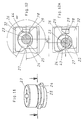
- eine perspektivische Ansicht der Tiefenverstellschraube;
- Fig. 12:
- eine Draufsicht auf die Tiefenverstellvorrichtung in einer ersten Stellung;
- Fig. 12A:
- eine Draufsicht auf die Tiefenverstellvorrichtung in einer zweiten Stellung;
- Fig. 13:
- einen Längsschnitt durch eine dritte Ausführungsform des erfindungsgemäßen Möbelscharniers;
- Fig. 14:
- eine Draufsicht auf die dritte Ausführungsform des Möbelscharniers gemäß Figur 13;
- Fig. 15:
- eine perspektivische Ansicht der Seitenverstellschraube;
- Fig. 16:
- eine Draufsicht auf die Seitenverstellvorrichtung in einer ersten Stellung;
- Fig. 16A:
- eine Draufsicht auf die Seitenverstellvorrichtung in einer zweiten Stellung.
- 1
- Grundplatte
- 2
- Stellplatte
- 3
- Lagerplatte
- 4
- Exzenterlager
- 5
- Durchbruch
- 6
- Langloch
- 7
- Lagerlappen
- 8
- Scharnierarm
- 9
- Führungsschlitz
- 10
- Scharniertopf
- 11
- Möbelseitenwand
- 12
- Möbeltür
- 13
- Seitenverstellschraube
- 14
- Schraubenkopf
- 15
- Exzenterscheibe
- 16
- Gewinde
- 17
- Tiefenverstellschraube
- 18
- Radius
- 19
- Drehpunkt
- 20
- Kreisbogen
- 21
- Pfeilrichtung
- 22
- Pfeilrichtung
- 23
- Tiefenverstellschraube
- 24
- Kurvenscheibe
- 25
- Kurvenscheibe
- 26
- Stellplatte
- 27
- Anlagefläche
- 28
- Abkröpfung
- 29
- Anlagefläche
- 30
- Langloch
- 31
- Durchbruch
- 32
- Durchbruch
- 33
- Lagerplatte
- 34
- Abkröpfung
- 35
- Seitenverstellschraube
- 36
- Kurvenscheibe
- 37
- Kurvenscheibe
- 38
- Gewinde
- 39
- Schraubenkopf
- 40
- Durchbruch
- 41
- Anlagefläche
- 42
- Anlagefläche
Claims (17)
- Möbelscharnier mit einer Verstelleinrichtung für einen mittelbar oder unmittelbar auf einer möbelseitigen, ein- oder mehrteiligen Montageplatte gelagerten Scharnierarm, der gelenkig mit einem türseitigen Anschlagteil verbunden ist, wobei die Verstelleinrichtung eine Seitenverstellschraube aufweist, mittels der die Position des Scharnierarms senkrecht zur Montageplatte zur seitlichen Verstellung der Türe veränderbar ist,
dadurch gekennzeichnet, daß die Seitenverstellschraube (13; 35) mindestens eine Exzenter- (15) oder Kurvenscheibe (36; 37) aufweist, wobei ein Verdrehen der Seitenverstellschraube (13; 25) eine Seitenverstellung und zugleich eine parallele Verschiebung des Scharnierarmes (8) relativ zur Montageplatte (1, 2; 1, 26) und damit eine Korrektur der Tiefenverstellung der Türe (12) um einen Betrag (K) bewirkt. - Möbelscharnier nach Anspruch 1,
dadurch gekennzeichnet, daß die Exzenter- (15) oder Kurvenscheibe (36; 37) mit einer Lagerplatte (3; 33) zusammenwirkt, die relativ zur Montageplatte (1, 2; 1, 26) feststellbar zwischen dem Scharnierarm (8) und der Montageplatte angeordnet ist. - Möbelscharnier nach einem der Ansprüche 1 oder 2,
dadurch gekennzeichnet, daß die Lagerplatte (3) ein Exzenterlager (4) umfaßt, an dem sich die Exzenterscheibe (15) abstützt. - Möbelscharnier nach einem der Ansprüche 1 oder 2,
dadurch gekennzeichnet, daß die Seitenverstellschraube (35) zwei etwa gegenläufige, übereinanderliegende Kurvenscheiben (36, 37) aufweist. - Möbelscharnier nach einem der Ansprüche 1 oder 2,
dadurch gekennzeichnet, daß die Lagerplatte (33) einen Durchbruch (40) aufweist, der Anlageflächen (41, 42) für die Kurvenscheibe(n) (36, 37) ausbildet. - Möbelscharnier nach einem der Ansprüche 1, 2, 4 oder 5,
dadurch gekennzeichnet, daß die Lagerplatte (33) eine Abkröpfung (34) aufweist, wodurch sich in zwei Ebenen übereinanderliegende Anlageflächen (41, 42) für die Kurvenscheiben (36, 37) ergeben. - Möbelscharnier nach einem der vorhergehenden Ansprüche,
dadurch gekennzeichnet, daß die Exzentrizität der Exzenter- (15) oder Kurvenscheibe(n) (36, 37) auf die Steigung des Gewindes der Seitenverstellschraube (13, 35) abgestimmt ist. - Möbelscharnier nach einem der vorhergehenden Ansprüche,
dadurch gekennzeichnet, daß die Verstelleinrichtung eine Tiefenverstellschraube (23) umfaßt, die am Scharnierarm (8) oder einem mit diesem verbundenen Bauteil (3) gelagert ist und mindestens eine Exzenter- oder Kurvenscheibe (24, 25) aufweist, die sich an zugeordneten Anlageflächen (27, 29) der Montageplatte (1, 26) abstützt und bei Verdrehung der Tiefenverstellschraube (23) eine Verschiebung des Scharnierarms (8) relativ zur Montageplatte (1, 26) um einen Betrag (W) bewirkt. - Möbelscharnier nach einem der vorhergehenden Ansprüche,
dadurch gekennzeichnet, daß die Verstelleinrichtung eine in einem zugeordneten Schraubgewinde der Montageplatte (1, 2) gelagerte Tiefenverstellschraube (17) umfaßt, und die Lagerplatte (3) ein von der Tiefenverstellschraube (17) durchsetztes Langloch (6) aufweist. - Möbelscharnier mit einer Verstelleinrichtung für einen mittelbar oder unmittelbar auf einer möbelseitigen, ein- oder mehrteiligen Montageplatte gelagerten Scharnierarm, der gelenkig mit einem türseitigen Anschlagteil verbunden ist, wobei die Verstelleinrichtung eine Tiefenverstellschraube aufweist, mittels der die Position des Scharnierarms parallel zur Montageplatte zur Tiefenverstellung der Türe veränderbar ist,
dadurch gekennzeichnet, daß die Tiefenverstellschraube (23) am Scharnierarm (8) oder einem mit diesem verbundenen Bauteil (3) gelagert ist und mindestens eine Exzenter- oder Kurvenscheibe (24, 25) aufweist, die sich an zugeordneten Anlageflächen (27, 29) der Montageplatte (1, 26) abstützt und ein Verdrehen der Tiefenverstellschraube (23) eine Verschiebung des Scharnierarms (8) relativ zur Montageplatte (1, 26) um einen Betrag (W) bewirkt. - Möbelscharnier nach Anspruch 10,
dadurch gekennzeichnet, daß die Tiefeneinstellschraube (23) drehbar in einer Lagerplatte (3) gelagert ist, die verschiebbar zwischen dem Scharnierarm (8) und der Montageplatte (1, 26) angeordnet ist. - Möbelscharnier nach Anspruch 10 oder 11,
dadurch gekennzeichnet, daß die Montageplatte eine Grundplatte (1) und eine Stellplatte (26) umfaßt. - Möbelscharnier nach Anspruch 10 bis 12,
dadurch gekennzeichnet, daß die Tiefenverstellschraube (23) zwei etwa gegenläufige, übereinanderliegende Kurvenscheiben (24, 25) aufweist. - Möbelscharnier nach Anspruch 10 bis 13,
dadurch gekennzeichnet, daß die Stellplatte (26) einen Durchbruch (32) aufweist, der die Anlageflächen (27, 29) für die Kurvenscheibe(n) ausbildet. - Möbelscharnier nach Anspruch 10 bis 14,
dadurch gekennzeichnet, daß die Stellplatte (3) eine Abkröpfung (28) aufweist, wodurch sich in zwei Ebenen übereinanderliegende Anlageflächen (27, 29) für die Kurvenscheiben (24, 25) ergeben. - Möbelscharnier nach Anspruch 10 bis 15,
dadurch gekennzeichnet, daß die Verstellvorrichtung eine Seitenverstellschraube (13) umfaßt, die mindestens eine Exzenter- (15) oder Kurvenscheibe (36, 37) aufweist, wobei bei Verdrehung der Seitenverstellschraube (13) eine Seitenverstellung und zugleich eine parallele Verschiebung des Scharnierarmes (8) relativ zur Montageplatte (1, 2; 1, 26) und damit eine Korrektur der Tiefenverstellung der Türe (12) um einen Betrag (K) bewirkt. - Möbelscharnier nach Anspruch 10 bis 16,
dadurch gekennzeichnet, daß die Lagerplatte (3, 33) Lagerlappen (7) aufweist, die in zugeordnete Führungsschlitze (9) des Scharnierarmes eingreifen und in diesen drehbar und verschiebbar geführt sind.
Applications Claiming Priority (2)
| Application Number | Priority Date | Filing Date | Title |
|---|---|---|---|
| DE10054238 | 2000-11-02 | ||
| DE10054238A DE10054238B4 (de) | 2000-11-02 | 2000-11-02 | Möbelscharnier |
Publications (3)
| Publication Number | Publication Date |
|---|---|
| EP1203861A2 true EP1203861A2 (de) | 2002-05-08 |
| EP1203861A3 EP1203861A3 (de) | 2004-01-07 |
| EP1203861B1 EP1203861B1 (de) | 2006-01-04 |
Family
ID=7661848
Family Applications (1)
| Application Number | Title | Priority Date | Filing Date |
|---|---|---|---|
| EP01124948A Expired - Lifetime EP1203861B1 (de) | 2000-11-02 | 2001-10-19 | Möbelscharnier |
Country Status (4)
| Country | Link |
|---|---|
| US (2) | US6615452B2 (de) |
| EP (1) | EP1203861B1 (de) |
| AT (2) | ATE315154T1 (de) |
| DE (2) | DE10054238B4 (de) |
Cited By (3)
| Publication number | Priority date | Publication date | Assignee | Title |
|---|---|---|---|---|
| WO2009127466A1 (de) | 2008-04-18 | 2009-10-22 | Paul Hettich Gmbh & Co. Kg | Verstellvorrichtung für möbel |
| FR2971308A1 (fr) * | 2011-02-03 | 2012-08-10 | Peugeot Citroen Automobiles Sa | Dispositif pour fixer ensemble deux pieces au moyen d'une vis engagee dans un trou oblong de l'une des pieces et vissee dans un fut taraude de l'autre piece. |
| WO2016045942A1 (de) * | 2014-09-26 | 2016-03-31 | Samet Kalip Ve Maden Esya San. Ve Tic. A.S. | Verstelleinrichtung |
Families Citing this family (22)
| Publication number | Priority date | Publication date | Assignee | Title |
|---|---|---|---|---|
| DE19920137C2 (de) * | 1999-05-03 | 2002-11-28 | Grass Gmbh Hoechst | Montageplatte für Möbelscharniere |
| DE20120238U1 (de) * | 2001-12-14 | 2003-04-24 | Lautenschlaeger Mepla Werke | Montageplatte zur verstellbaren Halterung von Möbelscharnieren am Korpus von Möbelstücken |
| DE10210017C1 (de) * | 2002-03-07 | 2003-07-31 | Grass Gmbh Hoechst | Möbelscharnier mit Verstelleinrichtung |
| US6883204B2 (en) * | 2002-05-29 | 2005-04-26 | Arturo Salice S.P.A. | Hinge |
| US20030221284A1 (en) * | 2002-06-03 | 2003-12-04 | Larsen, Joseph Bent | Face frame snap-on hinge |
| AT6962U1 (de) * | 2003-02-21 | 2004-06-25 | Blum Gmbh Julius | Scharnier |
| CN101006241B (zh) * | 2004-02-28 | 2011-11-16 | 索斯科公司 | 关节式铰链 |
| DE102004041300A1 (de) * | 2004-08-25 | 2006-03-02 | Lautenschläger, Horst | Verstelleinrichtung für Möbelteile |
| US7117561B1 (en) * | 2005-02-25 | 2006-10-10 | Grass America Inc. | Low profile hinge with three-dimensional mechanical adjustment |
| US7213300B1 (en) * | 2005-02-25 | 2007-05-08 | Grass America Inc. | Full overlay hinge with three-dimensional mechanical adjustment and side pins |
| SI1875024T1 (sl) * | 2005-04-29 | 2015-05-29 | Praemeta Gmbh & Co. Kg | Ĺ arnir |
| US7594300B2 (en) * | 2006-06-20 | 2009-09-29 | Hardware Resources, Inc. | Adjustable hinge |
| US8839488B2 (en) | 2006-06-20 | 2014-09-23 | Hardware Resources, Inc. | Adjustable hinge |
| EP2634334A4 (de) * | 2010-10-29 | 2016-06-08 | Sugatsune Kogyo | Scharniervorrichtung und basis für eine scharniervorrichtung |
| KR101268912B1 (ko) | 2012-11-06 | 2013-05-29 | 삼성정밀공업 주식회사 | 가구힌지의 가구도어 위치 조절장치 |
| US9163442B2 (en) | 2013-06-04 | 2015-10-20 | International Business Machines Corporation | Universal system for mounting rack doors |
| WO2015044895A2 (en) * | 2013-09-27 | 2015-04-02 | Bombardier Inc. | Adjustment device |
| US9169681B2 (en) * | 2014-01-31 | 2015-10-27 | Hardware Resources, Inc. | Low profile adjustable soft close hinge apparatus |
| US10081975B2 (en) * | 2014-01-31 | 2018-09-25 | Hardware Resources, Inc. | Low profile adjustable soft close hinge apparatus |
| DE102015003439B3 (de) * | 2015-03-17 | 2015-11-05 | Sfs Intec Holding Ag | Tür- oder Fensterscharnier |
| JP6537880B2 (ja) * | 2015-04-30 | 2019-07-03 | スガツネ工業株式会社 | ヒンジ |
| EP3486414A4 (de) * | 2016-07-14 | 2020-04-01 | Sugatsune Kogyo Co., Ltd. | Scharniervorrichtung |
Citations (2)
| Publication number | Priority date | Publication date | Assignee | Title |
|---|---|---|---|---|
| DE29811793U1 (de) | 1998-07-02 | 1999-11-18 | Mepla-Werke Lautenschläger GmbH & Co KG, 64354 Reinheim | Möbelscharnier |
| DE29914473U1 (de) | 1998-08-25 | 2000-01-05 | Julius Blum Ges.m.b.H., Höchst | Scharnier |
Family Cites Families (40)
| Publication number | Priority date | Publication date | Assignee | Title |
|---|---|---|---|---|
| US1336174A (en) * | 1919-09-23 | 1920-04-06 | Way John Howard | Concealed or invisible butt-hinge |
| DE2460127C3 (de) * | 1974-12-19 | 1981-11-05 | Karl Lautenschläger KG, Möbelbeschlagfabrik, 6107 Reinheim | Möbelscharnier |
| DE2542462A1 (de) * | 1975-09-24 | 1977-03-31 | Schulte Gmbh & Co Ewald | Scharnier |
| DE2635237A1 (de) * | 1976-08-05 | 1978-02-09 | Heinze Fa R | Moebelscharnier |
| FR2421594A1 (fr) * | 1977-06-20 | 1979-11-02 | Micro Mega Sa | Tete de contre-angle pour piece a main dentaire |
| DE3348215C2 (de) * | 1982-02-16 | 1993-05-19 | Industria Tecnica De La Bisagra, S.L., Aya, Guipuzcoa, Es | |
| DE3209900A1 (de) | 1982-03-18 | 1983-09-22 | Karl Lautenschläger KG, Möbelbeschlagfabrik, 6107 Reinheim | Kreuzgelenkscharnier |
| AT379851B (de) | 1983-03-21 | 1986-03-10 | Blum Gmbh Julius | Scharnier, insbesondere fuer moebeltueren |
| AT383390B (de) * | 1984-10-19 | 1987-06-25 | Blum Gmbh Julius | Scharnier |
| DE3448346C2 (de) | 1983-12-30 | 1990-12-13 | Julius Blum Ges.M.B.H., Hoechst, At | |
| AT384066B (de) | 1984-10-19 | 1987-09-25 | Blum Gmbh Julius | Scharnier |
| AT383643B (de) * | 1984-10-19 | 1987-07-27 | Blum Gmbh Julius | Scharnier |
| AT391344B (de) | 1987-08-31 | 1990-09-25 | Blum Gmbh Julius | Scharnier |
| DE3820338A1 (de) | 1988-06-15 | 1989-12-21 | Lautenschlaeger Kg Karl | Moebelscharnier |
| DE3841405A1 (de) | 1988-06-29 | 1990-01-04 | Salice Arturo Spa | Scharnierarm mit einer befestigungsplatte zu dessen befestigung an einem moebelteil o. dgl. |
| EP0369532B1 (de) | 1988-11-16 | 1994-04-13 | Franco Ferrari | Türscharnier mit Schnellkupplung |
| DE4009125A1 (de) | 1989-05-19 | 1991-09-26 | Salice Arturo Spa | Scharnier, vorzugsweise zur anlenkung einer tuer oder klappe an eine tragwand eines korpusteils |
| DE8907480U1 (de) | 1989-06-20 | 1989-08-03 | Karl Lautenschlaeger Gmbh & Co Kg Moebelbeschlagfabrik, 6107 Reinheim | Montageplatte für Möbelscharniere |
| ATE112358T1 (de) | 1989-12-25 | 1994-10-15 | Murakoshi Seiko Kk | Scharnier. |
| DE3943210C1 (de) | 1989-12-28 | 1991-06-20 | Arturo Salice S.P.A., Novedrate, Como, It | |
| DE4016664C2 (de) * | 1990-04-27 | 1993-11-11 | Salice Arturo Spa | Scharnier |
| JP2551740Y2 (ja) | 1991-10-09 | 1997-10-27 | 株式会社太田製作所 | スライドヒンジ |
| DE4211722A1 (de) | 1992-04-08 | 1993-10-14 | Lautenschlaeger Mepla Werke | Möbelscharnier |
| AT404858B (de) | 1993-10-25 | 1999-03-25 | Lautenschlaeger Mepla Werke | Als scharniertopf ausgebildeter tür-anschlagteil für möbelscharniere |
| DE4342744A1 (de) | 1993-12-15 | 1995-06-22 | Lautenschlaeger Mepla Werke | Möbelscharnier |
| AT1214U1 (de) * | 1995-12-18 | 1996-12-27 | Blum Gmbh Julius | Scharnier |
| IT1282620B1 (it) * | 1996-02-14 | 1998-03-31 | Franco Ferrari | Dispositivo di regolazione a camma per elementi di ferramenta per mobili ed elementi di ferramenta con esso |
| IT1283719B1 (it) * | 1996-04-05 | 1998-04-30 | Danco S P A | Braccio per cerniere di mobili e simili con mezzi a camma per la sua movimentazione in senso longitudinale. |
| GB2313405B (en) * | 1996-05-23 | 1999-11-17 | Securistyle Ltd | Rotary cam hinge adjuster |
| AT1787U1 (de) * | 1996-08-21 | 1997-11-25 | Blum Gmbh Julius | Scharnier für möbel |
| US5964011A (en) * | 1997-09-12 | 1999-10-12 | Newell Operating Company | Adjustable casement window hinge |
| US6061872A (en) | 1998-03-02 | 2000-05-16 | Grass Gmbh | Cabinet hinge |
| EP0967353A1 (de) * | 1998-06-26 | 1999-12-29 | Charmag S.A. | Scharnier |
| DE29817178U1 (de) * | 1998-09-24 | 1999-01-07 | Salice Arturo Spa | Scharnier, vorzugsweise Möbelscharnier |
| ATE302322T1 (de) * | 1999-02-11 | 2005-09-15 | Salice Arturo Spa | Vorrichtung zur befestigung eines beschlagteils, vorzugsweise des tragarms eines scharniers, an einer möbelwand o.dgl. |
| SI20218B (sl) * | 1999-04-30 | 2006-04-30 | Mednarodno Podjetje Lama D.D. Okovja - Montazni Sistemi - Orodja - Trgovina, Dekani | Osnovna plosca za sarnir |
| DE19920137C2 (de) | 1999-05-03 | 2002-11-28 | Grass Gmbh Hoechst | Montageplatte für Möbelscharniere |
| DE19951155C2 (de) * | 1999-10-23 | 2003-02-06 | Simonswerk,Gmbh | Scharniervorrichtung |
| US6470531B2 (en) * | 1999-11-05 | 2002-10-29 | Grass America, Inc. | Adjustable hinge |
| ATE404100T1 (de) * | 2000-10-27 | 2008-08-15 | Dorma Gmbh & Co Kg | Beschlag zur befestigung und justierung von glasscheiben |
-
2000
- 2000-11-02 DE DE10054238A patent/DE10054238B4/de not_active Expired - Fee Related
-
2001
- 2001-10-19 AT AT01124948T patent/ATE315154T1/de active
- 2001-10-19 DE DE50108606T patent/DE50108606D1/de not_active Expired - Fee Related
- 2001-10-19 EP EP01124948A patent/EP1203861B1/de not_active Expired - Lifetime
- 2001-10-29 AT AT0083401U patent/AT5923U1/de not_active IP Right Cessation
- 2001-11-02 US US10/003,156 patent/US6615452B2/en not_active Expired - Fee Related
-
2003
- 2003-06-12 US US10/460,593 patent/US6757939B2/en not_active Expired - Lifetime
Patent Citations (2)
| Publication number | Priority date | Publication date | Assignee | Title |
|---|---|---|---|---|
| DE29811793U1 (de) | 1998-07-02 | 1999-11-18 | Mepla-Werke Lautenschläger GmbH & Co KG, 64354 Reinheim | Möbelscharnier |
| DE29914473U1 (de) | 1998-08-25 | 2000-01-05 | Julius Blum Ges.m.b.H., Höchst | Scharnier |
Cited By (6)
| Publication number | Priority date | Publication date | Assignee | Title |
|---|---|---|---|---|
| WO2009127466A1 (de) | 2008-04-18 | 2009-10-22 | Paul Hettich Gmbh & Co. Kg | Verstellvorrichtung für möbel |
| CN102007259A (zh) * | 2008-04-18 | 2011-04-06 | 保罗海蒂诗有限及两合公司 | 用于家具的调节装置 |
| RU2508437C2 (ru) * | 2008-04-18 | 2014-02-27 | Пауль Хеттих Гмбх Унд Ко. Кг | Выдвижной ящик с регулировочным устройством |
| FR2971308A1 (fr) * | 2011-02-03 | 2012-08-10 | Peugeot Citroen Automobiles Sa | Dispositif pour fixer ensemble deux pieces au moyen d'une vis engagee dans un trou oblong de l'une des pieces et vissee dans un fut taraude de l'autre piece. |
| WO2016045942A1 (de) * | 2014-09-26 | 2016-03-31 | Samet Kalip Ve Maden Esya San. Ve Tic. A.S. | Verstelleinrichtung |
| US10660437B2 (en) | 2014-09-26 | 2020-05-26 | Samet Kalip Ve Maden Esya San. Ve Tic. A.S. | Adjustment device |
Also Published As
| Publication number | Publication date |
|---|---|
| EP1203861A3 (de) | 2004-01-07 |
| US6615452B2 (en) | 2003-09-09 |
| EP1203861B1 (de) | 2006-01-04 |
| DE50108606D1 (de) | 2006-03-30 |
| US20030204934A1 (en) | 2003-11-06 |
| US20020078527A1 (en) | 2002-06-27 |
| US6757939B2 (en) | 2004-07-06 |
| DE10054238A1 (de) | 2002-05-08 |
| ATE315154T1 (de) | 2006-02-15 |
| DE10054238B4 (de) | 2005-07-21 |
| AT5923U1 (de) | 2003-01-27 |
Similar Documents
| Publication | Publication Date | Title |
|---|---|---|
| EP1203861B1 (de) | Möbelscharnier | |
| DE102013112645B3 (de) | Türband | |
| DE19728641A1 (de) | Positionsscharnier für Türen | |
| EP2297418B1 (de) | Scharnier | |
| EP0437750A1 (de) | Befestigungsplatte zur Befestigung eines Scharnierarms | |
| DE69733852T2 (de) | Verstellnockeneinrichtung für Möbelbeschlagteile und Beschlagteile mit solch einer Einrichtung | |
| EP1342874B1 (de) | Möbelscharnier mit Verstelleinrichtung | |
| DE19947670B4 (de) | Drehband für Türen oder Fenster | |
| EP1236853B1 (de) | Scharnier mit Höheneinstellschraube | |
| EP3621484A2 (de) | Haltevorrichtung für eine frontblende einer schublade | |
| EP1625270B1 (de) | Deckelsteller | |
| EP1288415A1 (de) | Möbelscharnier | |
| WO2002086263A1 (de) | Tür- oder fensterscharnier | |
| DE202020004473U1 (de) | Einstellbares Scharnier für Fenster- oder Türbefestigungen | |
| AT390471B (de) | Moebelscharnier mit einer seiten- und tiefeneinstelleinrichtung | |
| EP0990477B1 (de) | Ausdrehkopf | |
| EP1223275B1 (de) | Band für Türen oder Fenster | |
| DE29612358U1 (de) | Möbelscharnier | |
| WO2007028497A1 (de) | Band für türen, fenster oder dergleichen | |
| DE20119264U1 (de) | Verstelleinrichtung eines Drehbandes | |
| DE3427397C2 (de) | ||
| EP0340455B2 (de) | Drehlager zur Verbindung zweier Flügel eines Fensters, einer Tür od. dgl. | |
| DE20120238U1 (de) | Montageplatte zur verstellbaren Halterung von Möbelscharnieren am Korpus von Möbelstücken | |
| EP0396209A2 (de) | Band für Türen, Fenster und dergleichen | |
| EP1054127B1 (de) | Beschlag zur Drehlagerung eines Flügels an einem Blendrahmen |
Legal Events
| Date | Code | Title | Description |
|---|---|---|---|
| PUAI | Public reference made under article 153(3) epc to a published international application that has entered the european phase |
Free format text: ORIGINAL CODE: 0009012 |
|
| AK | Designated contracting states |
Kind code of ref document: A2 Designated state(s): AT BE CH CY DE DK ES FI FR GB GR IE IT LI LU MC NL PT SE TR |
|
| AX | Request for extension of the european patent |
Free format text: AL;LT;LV;MK;RO;SI |
|
| PUAL | Search report despatched |
Free format text: ORIGINAL CODE: 0009013 |
|
| AK | Designated contracting states |
Kind code of ref document: A3 Designated state(s): AT BE CH CY DE DK ES FI FR GB GR IE IT LI LU MC NL PT SE TR |
|
| AX | Request for extension of the european patent |
Extension state: AL LT LV MK RO SI |
|
| 17P | Request for examination filed |
Effective date: 20040324 |
|
| AKX | Designation fees paid |
Designated state(s): AT BE CH CY DE DK ES FI FR GB GR IE IT LI LU MC NL PT SE TR |
|
| GRAP | Despatch of communication of intention to grant a patent |
Free format text: ORIGINAL CODE: EPIDOSNIGR1 |
|
| GRAS | Grant fee paid |
Free format text: ORIGINAL CODE: EPIDOSNIGR3 |
|
| GRAA | (expected) grant |
Free format text: ORIGINAL CODE: 0009210 |
|
| AK | Designated contracting states |
Kind code of ref document: B1 Designated state(s): AT BE CH CY DE DK ES FI FR GB GR IE IT LI LU MC NL PT SE TR |
|
| PG25 | Lapsed in a contracting state [announced via postgrant information from national office to epo] |
Ref country code: IT Free format text: LAPSE BECAUSE OF FAILURE TO SUBMIT A TRANSLATION OF THE DESCRIPTION OR TO PAY THE FEE WITHIN THE PRESCRIBED TIME-LIMIT;WARNING: LAPSES OF ITALIAN PATENTS WITH EFFECTIVE DATE BEFORE 2007 MAY HAVE OCCURRED AT ANY TIME BEFORE 2007. THE CORRECT EFFECTIVE DATE MAY BE DIFFERENT FROM THE ONE RECORDED. Effective date: 20060104 Ref country code: NL Free format text: LAPSE BECAUSE OF FAILURE TO SUBMIT A TRANSLATION OF THE DESCRIPTION OR TO PAY THE FEE WITHIN THE PRESCRIBED TIME-LIMIT Effective date: 20060104 Ref country code: IE Free format text: LAPSE BECAUSE OF FAILURE TO SUBMIT A TRANSLATION OF THE DESCRIPTION OR TO PAY THE FEE WITHIN THE PRESCRIBED TIME-LIMIT Effective date: 20060104 Ref country code: GB Free format text: LAPSE BECAUSE OF FAILURE TO SUBMIT A TRANSLATION OF THE DESCRIPTION OR TO PAY THE FEE WITHIN THE PRESCRIBED TIME-LIMIT Effective date: 20060104 Ref country code: FI Free format text: LAPSE BECAUSE OF FAILURE TO SUBMIT A TRANSLATION OF THE DESCRIPTION OR TO PAY THE FEE WITHIN THE PRESCRIBED TIME-LIMIT Effective date: 20060104 |
|
| REG | Reference to a national code |
Ref country code: GB Ref legal event code: FG4D Free format text: NOT ENGLISH |
|
| REG | Reference to a national code |
Ref country code: CH Ref legal event code: EP |
|
| REG | Reference to a national code |
Ref country code: IE Ref legal event code: FG4D Free format text: LANGUAGE OF EP DOCUMENT: GERMAN |
|
| REF | Corresponds to: |
Ref document number: 50108606 Country of ref document: DE Date of ref document: 20060330 Kind code of ref document: P |
|
| PG25 | Lapsed in a contracting state [announced via postgrant information from national office to epo] |
Ref country code: DK Free format text: LAPSE BECAUSE OF FAILURE TO SUBMIT A TRANSLATION OF THE DESCRIPTION OR TO PAY THE FEE WITHIN THE PRESCRIBED TIME-LIMIT Effective date: 20060404 Ref country code: SE Free format text: LAPSE BECAUSE OF FAILURE TO SUBMIT A TRANSLATION OF THE DESCRIPTION OR TO PAY THE FEE WITHIN THE PRESCRIBED TIME-LIMIT Effective date: 20060404 |
|
| PG25 | Lapsed in a contracting state [announced via postgrant information from national office to epo] |
Ref country code: ES Free format text: LAPSE BECAUSE OF FAILURE TO SUBMIT A TRANSLATION OF THE DESCRIPTION OR TO PAY THE FEE WITHIN THE PRESCRIBED TIME-LIMIT Effective date: 20060415 |
|
| PG25 | Lapsed in a contracting state [announced via postgrant information from national office to epo] |
Ref country code: PT Free format text: LAPSE BECAUSE OF FAILURE TO SUBMIT A TRANSLATION OF THE DESCRIPTION OR TO PAY THE FEE WITHIN THE PRESCRIBED TIME-LIMIT Effective date: 20060605 |
|
| NLV1 | Nl: lapsed or annulled due to failure to fulfill the requirements of art. 29p and 29m of the patents act | ||
| GBV | Gb: ep patent (uk) treated as always having been void in accordance with gb section 77(7)/1977 [no translation filed] |
Effective date: 20060104 |
|
| REG | Reference to a national code |
Ref country code: IE Ref legal event code: FD4D |
|
| PG25 | Lapsed in a contracting state [announced via postgrant information from national office to epo] |
Ref country code: MC Free format text: LAPSE BECAUSE OF NON-PAYMENT OF DUE FEES Effective date: 20061031 Ref country code: CH Free format text: LAPSE BECAUSE OF NON-PAYMENT OF DUE FEES Effective date: 20061031 Ref country code: LI Free format text: LAPSE BECAUSE OF NON-PAYMENT OF DUE FEES Effective date: 20061031 |
|
| PLBE | No opposition filed within time limit |
Free format text: ORIGINAL CODE: 0009261 |
|
| STAA | Information on the status of an ep patent application or granted ep patent |
Free format text: STATUS: NO OPPOSITION FILED WITHIN TIME LIMIT |
|
| 26N | No opposition filed |
Effective date: 20061005 |
|
| EN | Fr: translation not filed | ||
| PG25 | Lapsed in a contracting state [announced via postgrant information from national office to epo] |
Ref country code: DE Free format text: LAPSE BECAUSE OF NON-PAYMENT OF DUE FEES Effective date: 20070501 |
|
| REG | Reference to a national code |
Ref country code: CH Ref legal event code: PL |
|
| BERE | Be: lapsed |
Owner name: GRASS GMBH Effective date: 20061031 |
|
| PG25 | Lapsed in a contracting state [announced via postgrant information from national office to epo] |
Ref country code: FR Free format text: LAPSE BECAUSE OF FAILURE TO SUBMIT A TRANSLATION OF THE DESCRIPTION OR TO PAY THE FEE WITHIN THE PRESCRIBED TIME-LIMIT Effective date: 20070223 Ref country code: GR Free format text: LAPSE BECAUSE OF FAILURE TO SUBMIT A TRANSLATION OF THE DESCRIPTION OR TO PAY THE FEE WITHIN THE PRESCRIBED TIME-LIMIT Effective date: 20060405 |
|
| PG25 | Lapsed in a contracting state [announced via postgrant information from national office to epo] |
Ref country code: LU Free format text: LAPSE BECAUSE OF NON-PAYMENT OF DUE FEES Effective date: 20061019 |
|
| PG25 | Lapsed in a contracting state [announced via postgrant information from national office to epo] |
Ref country code: FR Free format text: LAPSE BECAUSE OF FAILURE TO SUBMIT A TRANSLATION OF THE DESCRIPTION OR TO PAY THE FEE WITHIN THE PRESCRIBED TIME-LIMIT Effective date: 20060104 Ref country code: CY Free format text: LAPSE BECAUSE OF FAILURE TO SUBMIT A TRANSLATION OF THE DESCRIPTION OR TO PAY THE FEE WITHIN THE PRESCRIBED TIME-LIMIT Effective date: 20060104 |
|
| PG25 | Lapsed in a contracting state [announced via postgrant information from national office to epo] |
Ref country code: BE Free format text: LAPSE BECAUSE OF FAILURE TO SUBMIT A TRANSLATION OF THE DESCRIPTION OR TO PAY THE FEE WITHIN THE PRESCRIBED TIME-LIMIT Effective date: 20061031 |
|
| PGFP | Annual fee paid to national office [announced via postgrant information from national office to epo] |
Ref country code: TR Payment date: 20101019 Year of fee payment: 10 Ref country code: IT Payment date: 20100927 Year of fee payment: 10 |
|
| PG25 | Lapsed in a contracting state [announced via postgrant information from national office to epo] |
Ref country code: IT Free format text: LAPSE BECAUSE OF NON-PAYMENT OF DUE FEES Effective date: 20111019 |
|
| PG25 | Lapsed in a contracting state [announced via postgrant information from national office to epo] |
Ref country code: TR Free format text: LAPSE BECAUSE OF NON-PAYMENT OF DUE FEES Effective date: 20111019 |
|
| PGFP | Annual fee paid to national office [announced via postgrant information from national office to epo] |
Ref country code: AT Payment date: 20131011 Year of fee payment: 13 |
|
| REG | Reference to a national code |
Ref country code: AT Ref legal event code: MM01 Ref document number: 315154 Country of ref document: AT Kind code of ref document: T Effective date: 20141019 |
|
| PG25 | Lapsed in a contracting state [announced via postgrant information from national office to epo] |
Ref country code: AT Free format text: LAPSE BECAUSE OF NON-PAYMENT OF DUE FEES Effective date: 20141019 |