EP1203866A2 - Anlage und Methode zur Regelung der Zufuhr von Wassernebel für den Verdichter einer Gasturbine - Google Patents
Anlage und Methode zur Regelung der Zufuhr von Wassernebel für den Verdichter einer Gasturbine Download PDFInfo
- Publication number
- EP1203866A2 EP1203866A2 EP01309402A EP01309402A EP1203866A2 EP 1203866 A2 EP1203866 A2 EP 1203866A2 EP 01309402 A EP01309402 A EP 01309402A EP 01309402 A EP01309402 A EP 01309402A EP 1203866 A2 EP1203866 A2 EP 1203866A2
- Authority
- EP
- European Patent Office
- Prior art keywords
- water
- air
- inlet
- mister
- compressor
- Prior art date
- Legal status (The legal status is an assumption and is not a legal conclusion. Google has not performed a legal analysis and makes no representation as to the accuracy of the status listed.)
- Granted
Links
Images
Classifications
-
- F—MECHANICAL ENGINEERING; LIGHTING; HEATING; WEAPONS; BLASTING
- F02—COMBUSTION ENGINES; HOT-GAS OR COMBUSTION-PRODUCT ENGINE PLANTS
- F02C—GAS-TURBINE PLANTS; AIR INTAKES FOR JET-PROPULSION PLANTS; CONTROLLING FUEL SUPPLY IN AIR-BREATHING JET-PROPULSION PLANTS
- F02C9/00—Controlling gas-turbine plants; Controlling fuel supply in air- breathing jet-propulsion plants
-
- F—MECHANICAL ENGINEERING; LIGHTING; HEATING; WEAPONS; BLASTING
- F01—MACHINES OR ENGINES IN GENERAL; ENGINE PLANTS IN GENERAL; STEAM ENGINES
- F01K—STEAM ENGINE PLANTS; STEAM ACCUMULATORS; ENGINE PLANTS NOT OTHERWISE PROVIDED FOR; ENGINES USING SPECIAL WORKING FLUIDS OR CYCLES
- F01K21/00—Steam engine plants not otherwise provided for
- F01K21/04—Steam engine plants not otherwise provided for using mixtures of steam and gas; Plants generating or heating steam by bringing water or steam into direct contact with hot gas
- F01K21/047—Steam engine plants not otherwise provided for using mixtures of steam and gas; Plants generating or heating steam by bringing water or steam into direct contact with hot gas having at least one combustion gas turbine
-
- F—MECHANICAL ENGINEERING; LIGHTING; HEATING; WEAPONS; BLASTING
- F02—COMBUSTION ENGINES; HOT-GAS OR COMBUSTION-PRODUCT ENGINE PLANTS
- F02C—GAS-TURBINE PLANTS; AIR INTAKES FOR JET-PROPULSION PLANTS; CONTROLLING FUEL SUPPLY IN AIR-BREATHING JET-PROPULSION PLANTS
- F02C7/00—Features, components parts, details or accessories, not provided for in, or of interest apart form groups F02C1/00 - F02C6/00; Air intakes for jet-propulsion plants
- F02C7/12—Cooling of plants
- F02C7/14—Cooling of plants of fluids in the plant, e.g. lubricant or fuel
- F02C7/141—Cooling of plants of fluids in the plant, e.g. lubricant or fuel of working fluid
- F02C7/143—Cooling of plants of fluids in the plant, e.g. lubricant or fuel of working fluid before or between the compressor stages
- F02C7/1435—Cooling of plants of fluids in the plant, e.g. lubricant or fuel of working fluid before or between the compressor stages by water injection
-
- Y—GENERAL TAGGING OF NEW TECHNOLOGICAL DEVELOPMENTS; GENERAL TAGGING OF CROSS-SECTIONAL TECHNOLOGIES SPANNING OVER SEVERAL SECTIONS OF THE IPC; TECHNICAL SUBJECTS COVERED BY FORMER USPC CROSS-REFERENCE ART COLLECTIONS [XRACs] AND DIGESTS
- Y10—TECHNICAL SUBJECTS COVERED BY FORMER USPC
- Y10S—TECHNICAL SUBJECTS COVERED BY FORMER USPC CROSS-REFERENCE ART COLLECTIONS [XRACs] AND DIGESTS
- Y10S261/00—Gas and liquid contact apparatus
- Y10S261/34—Automatic humidity regulation
Definitions
- the present invention relates to a gas turbine system and, in particular, a system for humidifying air supplied to the compressor using measurements of upstream conditions of air and water and the known flow rate of air through the turbine.
- power output from a gas turbine may be increased by spraying a fine mist of water droplets into the air upstream of the gas turbine compressor inlet.
- the water has the effect of lowering the temperature of the air supplied to the compressor inlet.
- the general practice of manufacturers of systems that supply a fine mist of water to an air stream of a compressor inlet is to use several water pumps of the same size, individually or together.
- the flow rate of water can be set equal to the flow rate of any individual pump or to the sum of the flow rates from two or more pumps.
- the flow rate may be varied through a system of control and bypass valves.
- the water flow control conventionally uses the measurement of the dry-bulb temperature of the air stream at a location downstream of the water injection. This practice is unreliable because any temperature sensor that is downstream of the water injection is prone to be impacted by water droplets, which cause the temperature measurement to be skewed toward the wet-bulb temperature.
- the water temperature to the misters is assumed to be the same as the wet-bulb temperature of the air, i.e., the evaporation process is assumed to occur at the wet-bulb temperature of air.
- a system for controlling desired flow rate of water to the misters without a temperature measurement downstream of the misters.
- This invention measures the temperatures of inlet air and inlet water upstream of the misters and, together with the known value of the flow rate of humidified air supplied to the compressor inlet and analysis of the mass- and heat-transfer processes, the flow rate of water supplied to the misters is determined. The inaccuracies inherent in the above-described prior art process are avoided.
- the magnitude of water to be added to the air stream is determined through the use of measured dry-bulb temperature and a measure of humidity such as dew point temperature, relative humidity or wet-bulb temperature of the ambient air upstream of the misters, together with the known value of the water temperature and the air flow rate.
- the method involves a determination of the humidity ratio (the mass of water vapor divided by the mass of dry air) of the upstream ambient air flow from the dry-bulb and dew point temperatures.
- the method also involves determination of the humidity ratio of saturated air at the desired downstream conditions where the water is completely evaporated.
- the difference between the humidity ratio of the upstream air and the humidity ratio of the downstream saturated air, or some user-defined fraction of this difference, is used to calculate the required flow rate of misted water per unit flow rate of air. These flow rates are expressed as mass per unit of time. Finally, the total flow rate of misted water is calculated from the known flow rate of misted air and the required flow rate of water per unit flow rate of air.
- the operator specifies the relative humidity of the air entering the compressor, e.g., 99% relative humidity.
- the required distance and the flow rate of water that creates the desired conditions for the downstream air involves an analysis of the heat- and mass-transfer processes, which are modeled using Film Theory. Since the processes are interdependent, this calculation involves an iterative solution.
- the heat- and mass-transfer processes result in a process of cooling the air stream that is similar to a constant wet-bulb process. In fact, the heat- and mass-transfer process is identical to a constant wet-bulb process when the water is delivered to the air stream at the wet-bulb temperature of the air.
- the present invention enables the water to be delivered to the air at a temperature greater than or less than the wet-bulb temperature without assuming the temperatures are the same.
- the Film Theory solution depends on the flow rate of the water, the temperature of the misted water, the diameter distribution of the water droplets, the humidity of the inlet air, the flow rate of the inlet air, the linear velocity of the inlet air, and the temperature of the inlet air.
- the mass-transfer models the evaporation of water before reaching the compressor. Also, the heat-transfer process is adiabatic, which yields a corresponding energy balance.
- the energy balance depends on the flow rate of the inlet air, the humidity of the inlet air, the dry-bulb temperature of the inlet air, the temperature of the inlet water, the flow rate of the inlet water and the humidity of the air entering the compressor.
- the mass-transfer relationship and the energy balance given by Film Theory the flow rate of misted water and the required distance for complete evaporation is determined from a relative humidity specified by the operator.
- the water is delivered to the air stream through a system of pumps, each of which is a different size.
- the second-smallest pump delivers water at twice the flow rate of the smallest pump.
- the third-smallest pump delivers water at twice the flow rate of the second-smallest pump.
- the fourth-smallest, e.g., the largest, pump has a variable speed control, such that the flow rate may be varied arbitrarily. In this way, the flow rate of water can be set to any value between the maximum capacity of the pumps and one-half the capacity. Flow rates less than one-half the maximum capacity can be set to increments of the smallest pump by turning on individual pumps.
- a method for providing humidified air to the compressor comprising the steps of determining a flow rate of water supplied to the water mister to humidify air supplied to the compressor to a predetermined relative humidity by sensing at least one property of the air in the air inlet to the water mister.
- a control system for a water mister in a gas turbine having a compressor, an inlet to the water mister for receiving air, and an inlet to the water mister for receiving water
- a method for providing humidified air to the compressor comprising the steps of sensing at least one property of the air supplied to the water mister and controlling the flow rate of water supplied to the water mister to humidify air supplied to the compressor to a predetermined relative humidity in accordance with the sensed property.
- an apparatus for supplying humidified air to a compressor in a gas turbine comprising a water mister, an inlet to the water mister for receiving air, an inlet to the water mister for receiving water, sensors for determining the temperature and humidity of air in the air inlet to the water mister and the temperature of water in the water inlet to the water mister, and a water flow controller for controlling the flow to the water mister in accordance with the sensed temperatures of the air and water in the inlets to the water mister to supply humidified air to the compressor.
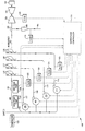
- FIGURE 1 is a schematic representation of a control system for humidifying air supplied to a compressor inlet of a gas turbine power plant in accordance with a preferred embodiment of the present invention.
- a system, generally designated 100, for controlling the humidification of inlet air entering a compressor is illustrated in Figure 1.
- the humidification system 100 has the following process inputs: ambient air via stream 101 and water via stream 102.
- the process outputs are humidified air via stream 103 for flow to the inlet of a compressor 104 and excess water, if any, via stream 105 that is not vaporized after the humidification process and before entry to the compressor 104.
- a turbine 106 and a generator 107 Also illustrated are a turbine 106 and a generator 107.
- Gas turbine 106 as conventional, drives generator 107 to generate electricity.
- Water entering the process via stream 102 is split into a plurality of streams, e.g., four streams each controlled by a separate pump.
- pump 108 pumps water via stream 112
- pump 109 pumps water via stream 113
- pump 110 pumps water via stream 114
- pump 111 pumps water via stream 115.
- Each pump is a different size, and the total flow rate of the water to the process can be controlled accordingly.
- pump 109 may be twice the size of pump 108
- pump 110 may be twice the size of pump 109
- pump 111 may be twice the size of pump 110.
- the largest pump e.g., pump 111, may be a variable speed pump.
- pumps 108, 109 and 110 may also be variable speed pumps
- a preferred embodiment of the present invention uses combinations of pumps to control the total flow rate of water in stream 102 and hence the magnitude of the water supplied through the misters or nozzles 116-119 and to the compressor inlet.
- TABLE 1 shows the relative flow rate units using various combinations of pumps in accordance with a preferred embodiment.
- Pump(s) in Operation Flow Rate Units Pump 108 1 Pump 109 2 Pump 108, Pump 109 3 Pump 110 4 Pump 108, Pump 110 5 Pump 109, Pump 110 6 Pump 108, Pump 109, Pump 110 7 Pump 111 8 Pump 108, Pump 111 9 Pump 109, Pump 111 10 Pump 108, Pump 109, Pump 111 11 Pump 110, Pump 111 12 Pump 108, Pump 110, Pump 111 13 Pump 109, Pump 110, Pump 111 14 Pump 108, Pump 109, Pump 110, Pump 111 15
- this system supplies water at flow rates in increments equal to one-fifteenth of the total flow rate using a binary-type method of counting, because each combination of pumps generates a unique flow rate. Additionally, since the largest pump, e.g., pump 110, has variable speeds, the flow rate may be varied arbitrarily. In this way, the flow rate of water in stream 102 can be set to any value between the maximum capacity of the pumps and one-half the capacity. Flow rates less than one-half the maximum capacity can be set equal to increments of the smallest pump, e.g., pump 108.
- water via stream 112 flows to misters or misting nozzles 116.
- water via stream 113 flows from pump 109 to misters or misting nozzles 117
- water via stream 114 flows from pump 110 to misters or misting nozzles 118
- water via stream 115 flows from pump 111 to misters or misting nozzles 119.
- Each misting nozzle creates a fine spray of water, allowing the ambient air via stream 101 to entrain the droplets of water from nozzles 116, 117, 118, and 119.
- the humidified air via stream 103 flows past a collector 130 that collects water in liquid form in stream 105.
- the water may be from water that either did not evaporate or condensed after evaporating.
- Collector 130 prevents water in liquid form from entering the compressor 104. Knowing the flow rate of water via stream 105 enables a more accurate calculation of water retained in stream 103.
- the relative humidity of humidified air in stream 103 is varied using only the flow rate of water in stream 102.
- An operator sets the desired relative humidity of air in stream 103, and water flow controller 120 operates pumps 108, 109, 110, and 111 to set the appropriate flow rate of water added to air in stream 101 to obtain that desired flow rate.
- Heat- and mass-transfer processes are analyzed, which have been modeled by using Film Theory. A number of variables are used to calculate the desired aggregate flow rate of water. However, no temperature measurements of the humidified air in stream 103 are used. Accordingly, the determined flow rate of water, based on heat- and mass-transfer processes, is more accurate than prior art processes.
- the water flow controller uses measurements of humidified air flow rate and temperature in controlling the humidification process.
- the total flow rate of humidified air via stream 103 provided compressor 104 is determined by extrinsic factors, e.g., the load on the power plant, the ratio of fuel to air, etc.
- water flow controller 120 only uses flow sensor 121 to measure the flow rate of humidified air via stream 103.
- the summation of the measurements made by flow sensors 122, 123, 124, and 125 equal the flow rate of water in stream 102.
- Flow sensors 122, 123, 124 and 125 measure the flow rates of water in streams 112, 113, 114 and 115, respectively.
- a single flow meter in stream 102 can be used.
- Flow sensor 126 measures the flow rate of water in stream 105 flowing from collector 130 and provides a signal to the controller 120.
- the water flow controller 120 reduces the flow rate of water via stream 102 appropriately in accordance with the magnitude of water not evaporated or condensed prior to entry of the humidified air to the compressor inlet.
- the amount of water that can be vaporized in stream 103 in the available distance before reaching compressor 104 depends on multiple factors, including the flow rate of water in stream 102, the diameter distribution of water droplets generated by misters or nozzles 116, 117, 118, and 119, the flow rate of air in stream 101, the velocity of air via stream 101, and the humidity of the air in stream 101.
- the diameter distribution of droplets remains substantially constant over time if no fouling of the misters 116, 117, 118, and 119 occurs.
- the velocity of air in stream 101 may be determined by dividing the volumetric flow rate of air by the cross-sectional area of stream 101.
- the humidity of air in stream 101 is determined using the wet-bulb and dry-bulb temperature sensors in stream 101.
- Dew point sensor 127 measures the dew point temperature of the air in stream 101.
- Dry-bulb thermometer 128 measures the dry-bulb temperature of the air in stream 101.
- a psychrometric chart at a pressure of one atmosphere may be used to determine the humidity ratio of air in stream 101, among other properties like relative humidity and enthalpy.
- Sensor, i.e., thermometer, 129 measures the temperature of the water in stream 102. The heat-transfer process is approximately adiabatic. Therefore, the thermal energy of the water and the thermal energy of the air in stream 101 supply the energy required to vaporize the water in streams 112, 113, 114, and 115.
- the energy in stream 101 is known from the enthalpy of dry air and water vapor in stream 101 which can be determined from the psychrometric chart and the flow rate of dry air and the humidity ratio in stream 101.
- the flow rate of dry air in stream 101 is equal to the measured flow rate of dry air in stream 103.
- the total flow rate of evaporated water can be determined using the flow rates of water in streams 112, 113, 114, and 115, and the flow rate of water in stream 105.
- the energy in water stream 102 is known, because the flow rate and the temperature of water in stream 102 are known.
- the temperature of the water in stream 102 determines the enthalpy of the water, and atmospheric pressure determines the latent heat of vaporization of the water.
- the temperature of the humidified air in stream 103 is generally cooler than the temperature of the air in stream 101, because the evaporation of water uses thermal energy of the air in stream 101. Assuming the humidified air in stream 103 has come to thermal equilibrium, i.e., the water droplets in the air have evaporated, the appropriate flow rate of water via stream 102 can be determined using an iterative process.
- the appropriate flow rate of water via stream 102 is determined iteratively, because the heat- and mass-transfer processes are interdependent.
- the amount of water that should be misted to obtain a predetermined relative humidity within the available distance depends on mass-transfer parameters, such as the flow rate of the water through misters or nozzles 116-119 and the temperature of the humidified air in stream 103.
- the mass-transfer process depends on the temperature of the water as a consequence of the vapor pressure of water.
- the heat-transfer process depends on the flow rates of the evaporated water as a consequence of the temperature of the water.
- the heat-transfer process alters the mass-transfer process, and vice-versa.
- Film Theory connects the two processes, the appropriate flow of water via stream 102 to obtain a predetermined relative humidity in stream 103 within the available distance cannot be obtained directly. Therefore, iterations are performed until the calculations converge on a value for flow of water via stream 102 corresponding to a resulting relative humidity of the humidified air via stream 103.
Landscapes
- Engineering & Computer Science (AREA)
- Chemical & Material Sciences (AREA)
- Combustion & Propulsion (AREA)
- Mechanical Engineering (AREA)
- General Engineering & Computer Science (AREA)
- Air Conditioning Control Device (AREA)
- Structures Of Non-Positive Displacement Pumps (AREA)
- Control Of Positive-Displacement Air Blowers (AREA)
- Air Humidification (AREA)
- Nozzles (AREA)
Applications Claiming Priority (2)
| Application Number | Priority Date | Filing Date | Title |
|---|---|---|---|
| US707247 | 2000-11-06 | ||
| US09/707,247 US6478289B1 (en) | 2000-11-06 | 2000-11-06 | Apparatus and methods for controlling the supply of water mist to a gas-turbine compressor |
Publications (3)
| Publication Number | Publication Date |
|---|---|
| EP1203866A2 true EP1203866A2 (de) | 2002-05-08 |
| EP1203866A3 EP1203866A3 (de) | 2004-08-25 |
| EP1203866B1 EP1203866B1 (de) | 2008-03-05 |
Family
ID=24840941
Family Applications (1)
| Application Number | Title | Priority Date | Filing Date |
|---|---|---|---|
| EP01309402A Expired - Lifetime EP1203866B1 (de) | 2000-11-06 | 2001-11-06 | Methode zur Regelung der Zufuhr von Wassernebel für den Verdichter einer Gasturbine |
Country Status (7)
| Country | Link |
|---|---|
| US (1) | US6478289B1 (de) |
| EP (1) | EP1203866B1 (de) |
| JP (1) | JP4160289B2 (de) |
| KR (1) | KR100705862B1 (de) |
| AT (1) | ATE388304T1 (de) |
| CZ (1) | CZ20013438A3 (de) |
| DE (1) | DE60133074T2 (de) |
Cited By (15)
| Publication number | Priority date | Publication date | Assignee | Title |
|---|---|---|---|---|
| WO2004025102A1 (en) * | 2002-09-12 | 2004-03-25 | Optiguide Controlled Humidity Ltd. | A gas turbine fogging system and methods for its control and trouble detection |
| WO2004051062A1 (de) * | 2002-12-02 | 2004-06-17 | Alstom Technology Ltd | Verfahren zur steuerung der flüssigkeitseinspritzung in einen zuströmkanal einer kraft- oder arbeitsmaschine |
| EP1462633A1 (de) * | 2003-03-28 | 2004-09-29 | Siemens Aktiengesellschaft | Temperaturmesseinrichtung und Regelung für die Heissgastemperatur einer Gasturbine |
| WO2004085816A1 (de) * | 2003-03-28 | 2004-10-07 | Siemens Aktiengesellschaft | TEMPERATURMESSEINRICHTUNG UND REGELUNG FÜR DIE HEIßGASTEMPERATUR EINER GASTURBINE |
| WO2005042947A1 (de) * | 2003-10-30 | 2005-05-12 | Alstom Technology Ltd | Verfahren zum betrieb einer kraftwerksanlage |
| WO2005021950A3 (de) * | 2003-09-01 | 2005-05-26 | Alstom Technology Ltd | Zerstäubungs- und eindüsungssystem, und verfahren zum betrieb |
| WO2005098217A1 (de) * | 2004-04-10 | 2005-10-20 | Alstom Technology Ltd | Verfahren und vorrichtung zum fördern einer flüssigkeit |
| WO2005124125A1 (de) * | 2004-06-22 | 2005-12-29 | Alstom Technology Ltd | Verfahren zum betrieb eines verdichters einer gasturbine bei verdunstungskühlung der verdichteransaugluft |
| US7562532B2 (en) | 2004-07-19 | 2009-07-21 | Alstom Technology Ltd | Method for operating a gas turbine group |
| EP1903188A3 (de) * | 2006-09-11 | 2009-11-25 | Gas Turbine Efficiency Sweden AB | System und Verfahren zur Erhöhung einer Turbinenleistung |
| US7712301B1 (en) | 2006-09-11 | 2010-05-11 | Gas Turbine Efficiency Sweden Ab | System and method for augmenting turbine power output |
| US7832213B2 (en) | 2007-03-27 | 2010-11-16 | Alstom Technology Ltd. | Operating method for a turbogroup |
| EP2136051A3 (de) * | 2008-06-20 | 2010-12-22 | Gas Turbine Efficiency Sweden AB | Leistungsverstärkungssystem einer Gasturbine |
| US10094288B2 (en) | 2012-07-24 | 2018-10-09 | Icr Turbine Engine Corporation | Ceramic-to-metal turbine volute attachment for a gas turbine engine |
| CN110624429A (zh) * | 2019-10-15 | 2019-12-31 | 中国船舶重工集团公司第七0三研究所 | 一种用于间冷循环船用燃气轮机的喷淋式水温调节装置 |
Families Citing this family (51)
| Publication number | Priority date | Publication date | Assignee | Title |
|---|---|---|---|---|
| US6715916B2 (en) * | 2001-02-08 | 2004-04-06 | General Electric Company | System and method for determining gas turbine firing and combustion reference temperatures having correction for water content in fuel |
| US6938425B2 (en) * | 2003-08-11 | 2005-09-06 | Siemens Westinghouse Power Corporation | System and method for controlling water injection in a turbine engine |
| DE10352088A1 (de) * | 2003-11-07 | 2005-08-11 | Alstom Technology Ltd | Verfahren zum Betrieb einer Zerstäubungsvorrichtung |
| US6938405B2 (en) * | 2003-11-13 | 2005-09-06 | General Electric Company | Spray nozzle grid configuration for gas turbine inlet misting system |
| DE102004004135A1 (de) * | 2004-01-28 | 2005-09-29 | Alstom Technology Ltd | Fördervorrichtung |
| KR100679639B1 (ko) * | 2004-12-02 | 2007-02-07 | 한국항공우주연구원 | 초음파 가습기가 장착된 압축기 |
| US7788930B2 (en) * | 2007-05-01 | 2010-09-07 | General Electric Company | Methods and systems for gas moisturization control |
| US8291714B2 (en) * | 2007-12-06 | 2012-10-23 | Rolls-Royce Power Endgineering PLC | Radial staging method and configuration of a liquid injection system for power plants |
| US8448433B2 (en) | 2008-04-09 | 2013-05-28 | Sustainx, Inc. | Systems and methods for energy storage and recovery using gas expansion and compression |
| US8479505B2 (en) | 2008-04-09 | 2013-07-09 | Sustainx, Inc. | Systems and methods for reducing dead volume in compressed-gas energy storage systems |
| US7958731B2 (en) | 2009-01-20 | 2011-06-14 | Sustainx, Inc. | Systems and methods for combined thermal and compressed gas energy conversion systems |
| US8037678B2 (en) | 2009-09-11 | 2011-10-18 | Sustainx, Inc. | Energy storage and generation systems and methods using coupled cylinder assemblies |
| US8250863B2 (en) | 2008-04-09 | 2012-08-28 | Sustainx, Inc. | Heat exchange with compressed gas in energy-storage systems |
| US8677744B2 (en) | 2008-04-09 | 2014-03-25 | SustaioX, Inc. | Fluid circulation in energy storage and recovery systems |
| US8359856B2 (en) | 2008-04-09 | 2013-01-29 | Sustainx Inc. | Systems and methods for efficient pumping of high-pressure fluids for energy storage and recovery |
| US7802426B2 (en) | 2008-06-09 | 2010-09-28 | Sustainx, Inc. | System and method for rapid isothermal gas expansion and compression for energy storage |
| WO2009126784A2 (en) | 2008-04-09 | 2009-10-15 | Sustainx, Inc. | Systems and methods for energy storage and recovery using compressed gas |
| US8240140B2 (en) | 2008-04-09 | 2012-08-14 | Sustainx, Inc. | High-efficiency energy-conversion based on fluid expansion and compression |
| US8474255B2 (en) | 2008-04-09 | 2013-07-02 | Sustainx, Inc. | Forming liquid sprays in compressed-gas energy storage systems for effective heat exchange |
| US20100307156A1 (en) | 2009-06-04 | 2010-12-09 | Bollinger Benjamin R | Systems and Methods for Improving Drivetrain Efficiency for Compressed Gas Energy Storage and Recovery Systems |
| US8225606B2 (en) | 2008-04-09 | 2012-07-24 | Sustainx, Inc. | Systems and methods for energy storage and recovery using rapid isothermal gas expansion and compression |
| US8381529B2 (en) * | 2009-01-29 | 2013-02-26 | General Electric Company | System and method for water injection in a turbine engine |
| US7963110B2 (en) | 2009-03-12 | 2011-06-21 | Sustainx, Inc. | Systems and methods for improving drivetrain efficiency for compressed gas energy storage |
| BRPI1007723A2 (pt) | 2009-05-12 | 2018-03-06 | Icr Turbine Engine Corp | sistema de armazenamento e conversão de turbina a gás |
| US8104274B2 (en) | 2009-06-04 | 2012-01-31 | Sustainx, Inc. | Increased power in compressed-gas energy storage and recovery |
| US20100326083A1 (en) * | 2009-06-26 | 2010-12-30 | Robert Bland | Spray system, power augmentation system for engine containing spray system and method of humidifying air |
| WO2011056855A1 (en) | 2009-11-03 | 2011-05-12 | Sustainx, Inc. | Systems and methods for compressed-gas energy storage using coupled cylinder assemblies |
| US20110173947A1 (en) * | 2010-01-19 | 2011-07-21 | General Electric Company | System and method for gas turbine power augmentation |
| US8866334B2 (en) | 2010-03-02 | 2014-10-21 | Icr Turbine Engine Corporation | Dispatchable power from a renewable energy facility |
| US8171728B2 (en) | 2010-04-08 | 2012-05-08 | Sustainx, Inc. | High-efficiency liquid heat exchange in compressed-gas energy storage systems |
| US8191362B2 (en) | 2010-04-08 | 2012-06-05 | Sustainx, Inc. | Systems and methods for reducing dead volume in compressed-gas energy storage systems |
| JP2011231739A (ja) * | 2010-04-30 | 2011-11-17 | Toshiba Corp | ガスタービン発電設備およびその運転方法 |
| US8234863B2 (en) | 2010-05-14 | 2012-08-07 | Sustainx, Inc. | Forming liquid sprays in compressed-gas energy storage systems for effective heat exchange |
| US8984895B2 (en) | 2010-07-09 | 2015-03-24 | Icr Turbine Engine Corporation | Metallic ceramic spool for a gas turbine engine |
| US8495872B2 (en) | 2010-08-20 | 2013-07-30 | Sustainx, Inc. | Energy storage and recovery utilizing low-pressure thermal conditioning for heat exchange with high-pressure gas |
| US8669670B2 (en) | 2010-09-03 | 2014-03-11 | Icr Turbine Engine Corporation | Gas turbine engine configurations |
| US8578708B2 (en) | 2010-11-30 | 2013-11-12 | Sustainx, Inc. | Fluid-flow control in energy storage and recovery systems |
| JP5562822B2 (ja) * | 2010-12-15 | 2014-07-30 | 株式会社東芝 | ガスタービン発電設備およびその運転方法 |
| WO2012105053A1 (ja) * | 2011-02-04 | 2012-08-09 | 株式会社日立製作所 | ガスタービン発電プラントの制御装置 |
| US9803549B2 (en) * | 2011-02-28 | 2017-10-31 | Ansaldo Energia Ip Uk Limited | Using return water of an evaporative intake air cooling system for cooling a component of a gas turbine |
| EP2715075A2 (de) | 2011-05-17 | 2014-04-09 | Sustainx, Inc. | Systeme und verfahren für effizienten zweiphasigen wärmetransfer in druckluftenergiespeichersystemen |
| US9051873B2 (en) | 2011-05-20 | 2015-06-09 | Icr Turbine Engine Corporation | Ceramic-to-metal turbine shaft attachment |
| US20130091834A1 (en) | 2011-10-14 | 2013-04-18 | Sustainx, Inc. | Dead-volume management in compressed-gas energy storage and recovery systems |
| US9816391B2 (en) | 2012-11-07 | 2017-11-14 | General Electric Company | Compressor wash system with spheroids |
| JP6180145B2 (ja) * | 2013-03-26 | 2017-08-16 | 三菱日立パワーシステムズ株式会社 | 吸気冷却装置 |
| US20150159509A1 (en) * | 2013-12-06 | 2015-06-11 | General Electric Company | Method and System for Dispensing Gas Turbine Anticorrosive Protection |
| US10557413B1 (en) * | 2014-11-26 | 2020-02-11 | Caldwell Tanks, Inc. | Systems and methods for controlling liquid flow to a turbine fogging array |
| ES2786301T3 (es) * | 2015-06-24 | 2020-10-09 | Aaf Ltd | Sistema para reducir la temperatura del aire de entrada de un dispositivo |
| US10961909B2 (en) * | 2018-05-15 | 2021-03-30 | General Electric Company | Variable evaporative cooling system |
| US11668239B2 (en) | 2020-06-24 | 2023-06-06 | General Electric Company | System and method for controlling temperature in an air intake |
| US20250122833A1 (en) * | 2023-10-17 | 2025-04-17 | Ge Infrastructure Technology Llc | Airless sprint & water wash system |
Family Cites Families (11)
| Publication number | Priority date | Publication date | Assignee | Title |
|---|---|---|---|---|
| US4702074A (en) * | 1985-07-30 | 1987-10-27 | Michael Munk | Internal combustion engine system with fog injection and heat exchange |
| US4730462A (en) * | 1986-05-05 | 1988-03-15 | Rogers Allen R | Evaporative precooling unit |
| DK170217B1 (da) * | 1993-06-04 | 1995-06-26 | Man B & W Diesel Gmbh | Stor trykladet forbrændingsmotor og fremgangsmåde til drift af en køler til afkøling af en sådan motors indsugningsluft. |
| US5463873A (en) * | 1993-12-06 | 1995-11-07 | Cool Fog Systems, Inc. | Method and apparatus for evaporative cooling of air leading to a gas turbine engine |
| US5867977A (en) * | 1996-05-14 | 1999-02-09 | The Dow Chemical Company | Method and apparatus for achieving power augmentation in gas turbines via wet compression |
| JP3401615B2 (ja) * | 1997-05-13 | 2003-04-28 | 吉秀 中村 | コンバインドサイクルシステムとその夏期における吸気冷却方法 |
| US6256976B1 (en) * | 1997-06-27 | 2001-07-10 | Hitachi, Ltd. | Exhaust gas recirculation type combined plant |
| JPH1172029A (ja) * | 1997-06-30 | 1999-03-16 | Hitachi Ltd | 水噴霧による出力増加機構を備えたガスタービン |
| SG104914A1 (en) * | 1997-06-30 | 2004-07-30 | Hitachi Ltd | Gas turbine |
| US6250064B1 (en) * | 1999-05-07 | 2001-06-26 | General Electric Co. | Gas turbine inlet air integrated water saturation and supersaturation system and related process |
| AU7340200A (en) * | 1999-09-03 | 2001-04-10 | Enhanced Turbine Output Holding, Llc | Gas turbine operative at high ambient temperatures |
-
2000
- 2000-11-06 US US09/707,247 patent/US6478289B1/en not_active Expired - Lifetime
-
2001
- 2001-09-25 CZ CZ20013438A patent/CZ20013438A3/cs unknown
- 2001-11-05 KR KR1020010068499A patent/KR100705862B1/ko not_active Expired - Fee Related
- 2001-11-06 AT AT01309402T patent/ATE388304T1/de not_active IP Right Cessation
- 2001-11-06 EP EP01309402A patent/EP1203866B1/de not_active Expired - Lifetime
- 2001-11-06 JP JP2001340177A patent/JP4160289B2/ja not_active Expired - Fee Related
- 2001-11-06 DE DE60133074T patent/DE60133074T2/de not_active Expired - Lifetime
Cited By (27)
| Publication number | Priority date | Publication date | Assignee | Title |
|---|---|---|---|---|
| WO2004025102A1 (en) * | 2002-09-12 | 2004-03-25 | Optiguide Controlled Humidity Ltd. | A gas turbine fogging system and methods for its control and trouble detection |
| WO2004051062A1 (de) * | 2002-12-02 | 2004-06-17 | Alstom Technology Ltd | Verfahren zur steuerung der flüssigkeitseinspritzung in einen zuströmkanal einer kraft- oder arbeitsmaschine |
| US7520137B2 (en) | 2002-12-02 | 2009-04-21 | Alstom Technology Ltd | Method of controlling the injection of liquid into an inflow duct of a prime mover or driven machine |
| US7513099B2 (en) | 2003-03-28 | 2009-04-07 | Siemens Aktiengesellschaft | Temperature measuring device and regulation of the temperature of hot gas of a gas turbine |
| EP1462633A1 (de) * | 2003-03-28 | 2004-09-29 | Siemens Aktiengesellschaft | Temperaturmesseinrichtung und Regelung für die Heissgastemperatur einer Gasturbine |
| WO2004085816A1 (de) * | 2003-03-28 | 2004-10-07 | Siemens Aktiengesellschaft | TEMPERATURMESSEINRICHTUNG UND REGELUNG FÜR DIE HEIßGASTEMPERATUR EINER GASTURBINE |
| US8141369B2 (en) | 2003-03-28 | 2012-03-27 | Siemens Aktiengesellschaft | Method of regulation of the temperature of hot gas of a gas turbine |
| WO2005021950A3 (de) * | 2003-09-01 | 2005-05-26 | Alstom Technology Ltd | Zerstäubungs- und eindüsungssystem, und verfahren zum betrieb |
| US7832192B2 (en) | 2003-09-01 | 2010-11-16 | Alstom Technology Ltd | Method for injecting a liquid mist into an intake duct |
| WO2005042947A1 (de) * | 2003-10-30 | 2005-05-12 | Alstom Technology Ltd | Verfahren zum betrieb einer kraftwerksanlage |
| US7481060B2 (en) | 2003-10-30 | 2009-01-27 | Alstom Technology Ltd | Method for operating a power plant |
| WO2005098217A1 (de) * | 2004-04-10 | 2005-10-20 | Alstom Technology Ltd | Verfahren und vorrichtung zum fördern einer flüssigkeit |
| US7841183B2 (en) | 2004-04-10 | 2010-11-30 | Alstom Technology Ltd | Method and apparatus for delivering a liquid |
| CH697258B1 (de) * | 2004-06-22 | 2008-07-31 | Alstom Technology Ltd | Verfahren zum Betrieb einer Gasturbine. |
| WO2005124125A1 (de) * | 2004-06-22 | 2005-12-29 | Alstom Technology Ltd | Verfahren zum betrieb eines verdichters einer gasturbine bei verdunstungskühlung der verdichteransaugluft |
| US7428819B2 (en) | 2004-06-22 | 2008-09-30 | Alstom Technology Ltd. | Method for the operation of a compressor of a gas turbine with evaporative cooling of the compressor induction air |
| US7562532B2 (en) | 2004-07-19 | 2009-07-21 | Alstom Technology Ltd | Method for operating a gas turbine group |
| EP2275648A1 (de) * | 2006-09-11 | 2011-01-19 | Gas Turbine Efficiency Sweden AB | System und Verfahren zur Erhöhung einer Turbinenleistung |
| US7712301B1 (en) | 2006-09-11 | 2010-05-11 | Gas Turbine Efficiency Sweden Ab | System and method for augmenting turbine power output |
| US7703272B2 (en) | 2006-09-11 | 2010-04-27 | Gas Turbine Efficiency Sweden Ab | System and method for augmenting turbine power output |
| EP1903188A3 (de) * | 2006-09-11 | 2009-11-25 | Gas Turbine Efficiency Sweden AB | System und Verfahren zur Erhöhung einer Turbinenleistung |
| US7832213B2 (en) | 2007-03-27 | 2010-11-16 | Alstom Technology Ltd. | Operating method for a turbogroup |
| DE102007015309B4 (de) | 2007-03-27 | 2023-01-05 | Ansaldo Energia Switzerland AG | Betriebsverfahren für eine Turbogruppe |
| EP2136051A3 (de) * | 2008-06-20 | 2010-12-22 | Gas Turbine Efficiency Sweden AB | Leistungsverstärkungssystem einer Gasturbine |
| CN101608576B (zh) * | 2008-06-20 | 2013-06-05 | 燃气涡轮机效率瑞典公司 | 用于功率增大系统的撬装设备结构 |
| US10094288B2 (en) | 2012-07-24 | 2018-10-09 | Icr Turbine Engine Corporation | Ceramic-to-metal turbine volute attachment for a gas turbine engine |
| CN110624429A (zh) * | 2019-10-15 | 2019-12-31 | 中国船舶重工集团公司第七0三研究所 | 一种用于间冷循环船用燃气轮机的喷淋式水温调节装置 |
Also Published As
| Publication number | Publication date |
|---|---|
| JP4160289B2 (ja) | 2008-10-01 |
| ATE388304T1 (de) | 2008-03-15 |
| DE60133074T2 (de) | 2009-03-12 |
| CZ20013438A3 (cs) | 2002-06-12 |
| KR100705862B1 (ko) | 2007-04-09 |
| EP1203866A3 (de) | 2004-08-25 |
| JP2002201958A (ja) | 2002-07-19 |
| DE60133074D1 (de) | 2008-04-17 |
| US6478289B1 (en) | 2002-11-12 |
| EP1203866B1 (de) | 2008-03-05 |
| KR20020035447A (ko) | 2002-05-11 |
Similar Documents
| Publication | Publication Date | Title |
|---|---|---|
| US6478289B1 (en) | Apparatus and methods for controlling the supply of water mist to a gas-turbine compressor | |
| US5525268A (en) | Humidifying system | |
| CA2060999C (en) | Air pre-cooler method and apparatus | |
| US20110023506A1 (en) | Evaporative pre-cooler for air cooled heat exchangers | |
| EP1225306A1 (de) | Regelsystem und Methode für Gasturbineneinlass-Luft Wassersättigung und Übersättigungssystem | |
| US8402735B2 (en) | Cooling apparatus, gas turbine system using cooling apparatus, heat pump system using cooling system, cooling method, and method for operating cooling apparatus | |
| JP5097852B1 (ja) | 空気調和方法および空気調和装置 | |
| JP4954665B2 (ja) | 二流体水噴霧ノズルの比例制御方法とその装置。 | |
| KR101516772B1 (ko) | 온습도 조정 장치 및 온습도 조정 방법 | |
| CN112271311B (zh) | 一种燃料电池的控制系统及其方法 | |
| US20150121881A1 (en) | Gas turbine inlet system and related method for cooling gas turbine inlet air | |
| JPH04288418A (ja) | エア・コンデイショニングの方法およびそのための装置 | |
| WO2003089770A1 (en) | Water injection for gas turbine inlet air | |
| JP2001234755A (ja) | ガスタービンプラント | |
| JP3793910B2 (ja) | ガスタービン複合発電プラントとその運転方法 | |
| Isakhodjayev et al. | Development of a laboratory nozzle chamber installation for the humidification of buildings | |
| CN116399607B (zh) | 一种航空发动机可变进气湿度快速模拟方法 | |
| JP2009133318A (ja) | 複数の中間冷却器を備えた圧縮機を有するシステム,冷却方法 | |
| CN116956477A (zh) | 适用于燃煤电站湿烟气提水冷凝塔设计和运行的计算方法 | |
| JP2005164081A (ja) | ガスタービンシステム | |
| JP2004044867A (ja) | 気体調湿方法および気体調湿装置 | |
| Trewin | Inlet-temperature suppression of inlet air for gas-turbine compressors by evaporative cooling of water spray | |
| CN119783278B (zh) | 姿控发动机高空模拟试验系统的降温冷却性能指标分析及计算方法 | |
| Jassim | Thermal performance evaluation of water mist assisted air conditioner | |
| US2892322A (en) | Air cycle air conditioning system |
Legal Events
| Date | Code | Title | Description |
|---|---|---|---|
| PUAI | Public reference made under article 153(3) epc to a published international application that has entered the european phase |
Free format text: ORIGINAL CODE: 0009012 |
|
| AK | Designated contracting states |
Kind code of ref document: A2 Designated state(s): AT BE CH CY DE DK ES FI FR GB GR IE IT LI LU MC NL PT SE TR |
|
| AX | Request for extension of the european patent |
Free format text: AL;LT;LV;MK;RO;SI |
|
| PUAL | Search report despatched |
Free format text: ORIGINAL CODE: 0009013 |
|
| AK | Designated contracting states |
Kind code of ref document: A3 Designated state(s): AT BE CH CY DE DK ES FI FR GB GR IE IT LI LU MC NL PT SE TR |
|
| AX | Request for extension of the european patent |
Extension state: AL LT LV MK RO SI |
|
| RIC1 | Information provided on ipc code assigned before grant |
Ipc: 7F 02C 3/30 B Ipc: 7F 02C 7/143 B Ipc: 7F 01K 21/04 A |
|
| 17P | Request for examination filed |
Effective date: 20050225 |
|
| AKX | Designation fees paid |
Designated state(s): AT BE CH CY DE DK ES FI FR GB GR IE IT LI LU MC NL PT SE TR |
|
| 17Q | First examination report despatched |
Effective date: 20050608 |
|
| GRAP | Despatch of communication of intention to grant a patent |
Free format text: ORIGINAL CODE: EPIDOSNIGR1 |
|
| RTI1 | Title (correction) |
Free format text: METHOD FOR CONTROLLING THE SUPPLY OF WATER MIST TO A GAS-TURBINE COMPRESSOR |
|
| GRAS | Grant fee paid |
Free format text: ORIGINAL CODE: EPIDOSNIGR3 |
|
| GRAA | (expected) grant |
Free format text: ORIGINAL CODE: 0009210 |
|
| AK | Designated contracting states |
Kind code of ref document: B1 Designated state(s): AT BE CH CY DE DK ES FI FR GB GR IE IT LI LU MC NL PT SE TR |
|
| REG | Reference to a national code |
Ref country code: GB Ref legal event code: FG4D |
|
| REG | Reference to a national code |
Ref country code: CH Ref legal event code: EP |
|
| REG | Reference to a national code |
Ref country code: IE Ref legal event code: FG4D |
|
| REF | Corresponds to: |
Ref document number: 60133074 Country of ref document: DE Date of ref document: 20080417 Kind code of ref document: P |
|
| REG | Reference to a national code |
Ref country code: CH Ref legal event code: NV Representative=s name: SERVOPATENT GMBH |
|
| REG | Reference to a national code |
Ref country code: SE Ref legal event code: TRGR |
|
| REG | Reference to a national code |
Ref country code: CH Ref legal event code: NV Representative=s name: SERVOPATENT GMBH |
|
| PG25 | Lapsed in a contracting state [announced via postgrant information from national office to epo] |
Ref country code: ES Free format text: LAPSE BECAUSE OF FAILURE TO SUBMIT A TRANSLATION OF THE DESCRIPTION OR TO PAY THE FEE WITHIN THE PRESCRIBED TIME-LIMIT Effective date: 20080616 Ref country code: FI Free format text: LAPSE BECAUSE OF FAILURE TO SUBMIT A TRANSLATION OF THE DESCRIPTION OR TO PAY THE FEE WITHIN THE PRESCRIBED TIME-LIMIT Effective date: 20080305 |
|
| PG25 | Lapsed in a contracting state [announced via postgrant information from national office to epo] |
Ref country code: AT Free format text: LAPSE BECAUSE OF FAILURE TO SUBMIT A TRANSLATION OF THE DESCRIPTION OR TO PAY THE FEE WITHIN THE PRESCRIBED TIME-LIMIT Effective date: 20080305 |
|
| PG25 | Lapsed in a contracting state [announced via postgrant information from national office to epo] |
Ref country code: BE Free format text: LAPSE BECAUSE OF FAILURE TO SUBMIT A TRANSLATION OF THE DESCRIPTION OR TO PAY THE FEE WITHIN THE PRESCRIBED TIME-LIMIT Effective date: 20080305 |
|
| PG25 | Lapsed in a contracting state [announced via postgrant information from national office to epo] |
Ref country code: PT Free format text: LAPSE BECAUSE OF FAILURE TO SUBMIT A TRANSLATION OF THE DESCRIPTION OR TO PAY THE FEE WITHIN THE PRESCRIBED TIME-LIMIT Effective date: 20080805 |
|
| ET | Fr: translation filed | ||
| PLBE | No opposition filed within time limit |
Free format text: ORIGINAL CODE: 0009261 |
|
| STAA | Information on the status of an ep patent application or granted ep patent |
Free format text: STATUS: NO OPPOSITION FILED WITHIN TIME LIMIT |
|
| PG25 | Lapsed in a contracting state [announced via postgrant information from national office to epo] |
Ref country code: DK Free format text: LAPSE BECAUSE OF FAILURE TO SUBMIT A TRANSLATION OF THE DESCRIPTION OR TO PAY THE FEE WITHIN THE PRESCRIBED TIME-LIMIT Effective date: 20080305 |
|
| 26N | No opposition filed |
Effective date: 20081208 |
|
| PG25 | Lapsed in a contracting state [announced via postgrant information from national office to epo] |
Ref country code: MC Free format text: LAPSE BECAUSE OF NON-PAYMENT OF DUE FEES Effective date: 20081130 |
|
| PG25 | Lapsed in a contracting state [announced via postgrant information from national office to epo] |
Ref country code: CY Free format text: LAPSE BECAUSE OF FAILURE TO SUBMIT A TRANSLATION OF THE DESCRIPTION OR TO PAY THE FEE WITHIN THE PRESCRIBED TIME-LIMIT Effective date: 20080305 |
|
| PG25 | Lapsed in a contracting state [announced via postgrant information from national office to epo] |
Ref country code: IE Free format text: LAPSE BECAUSE OF NON-PAYMENT OF DUE FEES Effective date: 20081106 |
|
| PG25 | Lapsed in a contracting state [announced via postgrant information from national office to epo] |
Ref country code: LU Free format text: LAPSE BECAUSE OF NON-PAYMENT OF DUE FEES Effective date: 20081106 |
|
| PG25 | Lapsed in a contracting state [announced via postgrant information from national office to epo] |
Ref country code: TR Free format text: LAPSE BECAUSE OF FAILURE TO SUBMIT A TRANSLATION OF THE DESCRIPTION OR TO PAY THE FEE WITHIN THE PRESCRIBED TIME-LIMIT Effective date: 20080305 |
|
| PG25 | Lapsed in a contracting state [announced via postgrant information from national office to epo] |
Ref country code: GR Free format text: LAPSE BECAUSE OF FAILURE TO SUBMIT A TRANSLATION OF THE DESCRIPTION OR TO PAY THE FEE WITHIN THE PRESCRIBED TIME-LIMIT Effective date: 20080606 |
|
| REG | Reference to a national code |
Ref country code: FR Ref legal event code: PLFP Year of fee payment: 15 |
|
| PGFP | Annual fee paid to national office [announced via postgrant information from national office to epo] |
Ref country code: GB Payment date: 20151127 Year of fee payment: 15 |
|
| PGFP | Annual fee paid to national office [announced via postgrant information from national office to epo] |
Ref country code: NL Payment date: 20151126 Year of fee payment: 15 Ref country code: SE Payment date: 20151127 Year of fee payment: 15 |
|
| REG | Reference to a national code |
Ref country code: FR Ref legal event code: PLFP Year of fee payment: 16 |
|
| REG | Reference to a national code |
Ref country code: SE Ref legal event code: EUG |
|
| REG | Reference to a national code |
Ref country code: NL Ref legal event code: MM Effective date: 20161201 |
|
| GBPC | Gb: european patent ceased through non-payment of renewal fee |
Effective date: 20161106 |
|
| PG25 | Lapsed in a contracting state [announced via postgrant information from national office to epo] |
Ref country code: SE Free format text: LAPSE BECAUSE OF NON-PAYMENT OF DUE FEES Effective date: 20161107 |
|
| PG25 | Lapsed in a contracting state [announced via postgrant information from national office to epo] |
Ref country code: NL Free format text: LAPSE BECAUSE OF NON-PAYMENT OF DUE FEES Effective date: 20161201 |
|
| REG | Reference to a national code |
Ref country code: FR Ref legal event code: PLFP Year of fee payment: 17 |
|
| PG25 | Lapsed in a contracting state [announced via postgrant information from national office to epo] |
Ref country code: GB Free format text: LAPSE BECAUSE OF NON-PAYMENT OF DUE FEES Effective date: 20161106 |
|
| REG | Reference to a national code |
Ref country code: FR Ref legal event code: PLFP Year of fee payment: 18 |
|
| PGFP | Annual fee paid to national office [announced via postgrant information from national office to epo] |
Ref country code: DE Payment date: 20181023 Year of fee payment: 18 |
|
| PGFP | Annual fee paid to national office [announced via postgrant information from national office to epo] |
Ref country code: FR Payment date: 20181024 Year of fee payment: 18 Ref country code: IT Payment date: 20181023 Year of fee payment: 18 Ref country code: CH Payment date: 20181030 Year of fee payment: 18 |
|
| REG | Reference to a national code |
Ref country code: DE Ref legal event code: R119 Ref document number: 60133074 Country of ref document: DE |
|
| REG | Reference to a national code |
Ref country code: CH Ref legal event code: PCAR Free format text: NEW ADDRESS: WANNERSTRASSE 9/1, 8045 ZUERICH (CH) |
|
| REG | Reference to a national code |
Ref country code: CH Ref legal event code: PL |
|
| PG25 | Lapsed in a contracting state [announced via postgrant information from national office to epo] |
Ref country code: LI Free format text: LAPSE BECAUSE OF NON-PAYMENT OF DUE FEES Effective date: 20191130 Ref country code: CH Free format text: LAPSE BECAUSE OF NON-PAYMENT OF DUE FEES Effective date: 20191130 |
|
| PG25 | Lapsed in a contracting state [announced via postgrant information from national office to epo] |
Ref country code: FR Free format text: LAPSE BECAUSE OF NON-PAYMENT OF DUE FEES Effective date: 20191130 Ref country code: DE Free format text: LAPSE BECAUSE OF NON-PAYMENT OF DUE FEES Effective date: 20200603 Ref country code: IT Free format text: LAPSE BECAUSE OF NON-PAYMENT OF DUE FEES Effective date: 20191106 |