EP1203894B1 - Dispositif de refroidissement pour un palier - Google Patents
Dispositif de refroidissement pour un palier Download PDFInfo
- Publication number
- EP1203894B1 EP1203894B1 EP01126026A EP01126026A EP1203894B1 EP 1203894 B1 EP1203894 B1 EP 1203894B1 EP 01126026 A EP01126026 A EP 01126026A EP 01126026 A EP01126026 A EP 01126026A EP 1203894 B1 EP1203894 B1 EP 1203894B1
- Authority
- EP
- European Patent Office
- Prior art keywords
- bearing
- cooling
- cooling medium
- shaft part
- medium passage
- Prior art date
- Legal status (The legal status is an assumption and is not a legal conclusion. Google has not performed a legal analysis and makes no representation as to the accuracy of the status listed.)
- Expired - Lifetime
Links
- 238000001816 cooling Methods 0.000 title claims description 36
- 239000002826 coolant Substances 0.000 claims description 50
- 238000000638 solvent extraction Methods 0.000 claims description 9
- 239000012530 fluid Substances 0.000 claims description 4
- 238000005461 lubrication Methods 0.000 claims description 4
- 239000011347 resin Substances 0.000 description 16
- 229920005989 resin Polymers 0.000 description 16
- 238000000034 method Methods 0.000 description 5
- 239000000314 lubricant Substances 0.000 description 4
- 238000010276 construction Methods 0.000 description 3
- 230000001965 increasing effect Effects 0.000 description 3
- 238000004519 manufacturing process Methods 0.000 description 3
- 230000002093 peripheral effect Effects 0.000 description 2
- 238000003466 welding Methods 0.000 description 2
- 229910000831 Steel Inorganic materials 0.000 description 1
- 230000002708 enhancing effect Effects 0.000 description 1
- 230000020169 heat generation Effects 0.000 description 1
- 238000010438 heat treatment Methods 0.000 description 1
- 238000010008 shearing Methods 0.000 description 1
- 239000010959 steel Substances 0.000 description 1
- 238000005728 strengthening Methods 0.000 description 1
Images

Classifications
-
- F—MECHANICAL ENGINEERING; LIGHTING; HEATING; WEAPONS; BLASTING
- F16—ENGINEERING ELEMENTS AND UNITS; GENERAL MEASURES FOR PRODUCING AND MAINTAINING EFFECTIVE FUNCTIONING OF MACHINES OR INSTALLATIONS; THERMAL INSULATION IN GENERAL
- F16C—SHAFTS; FLEXIBLE SHAFTS; ELEMENTS OR CRANKSHAFT MECHANISMS; ROTARY BODIES OTHER THAN GEARING ELEMENTS; BEARINGS
- F16C37/00—Cooling of bearings
- F16C37/002—Cooling of bearings of fluid bearings
-
- B—PERFORMING OPERATIONS; TRANSPORTING
- B29—WORKING OF PLASTICS; WORKING OF SUBSTANCES IN A PLASTIC STATE IN GENERAL
- B29C—SHAPING OR JOINING OF PLASTICS; SHAPING OF MATERIAL IN A PLASTIC STATE, NOT OTHERWISE PROVIDED FOR; AFTER-TREATMENT OF THE SHAPED PRODUCTS, e.g. REPAIRING
- B29C48/00—Extrusion moulding, i.e. expressing the moulding material through a die or nozzle which imparts the desired form; Apparatus therefor
- B29C48/25—Component parts, details or accessories; Auxiliary operations
- B29C48/36—Means for plasticising or homogenising the moulding material or forcing it through the nozzle or die
- B29C48/365—Means for plasticising or homogenising the moulding material or forcing it through the nozzle or die using pumps, e.g. piston pumps
- B29C48/37—Gear pumps
-
- B—PERFORMING OPERATIONS; TRANSPORTING
- B29—WORKING OF PLASTICS; WORKING OF SUBSTANCES IN A PLASTIC STATE IN GENERAL
- B29C—SHAPING OR JOINING OF PLASTICS; SHAPING OF MATERIAL IN A PLASTIC STATE, NOT OTHERWISE PROVIDED FOR; AFTER-TREATMENT OF THE SHAPED PRODUCTS, e.g. REPAIRING
- B29C48/00—Extrusion moulding, i.e. expressing the moulding material through a die or nozzle which imparts the desired form; Apparatus therefor
- B29C48/25—Component parts, details or accessories; Auxiliary operations
- B29C48/78—Thermal treatment of the extrusion moulding material or of preformed parts or layers, e.g. by heating or cooling
- B29C48/80—Thermal treatment of the extrusion moulding material or of preformed parts or layers, e.g. by heating or cooling at the plasticising zone, e.g. by heating cylinders
- B29C48/83—Heating or cooling the cylinders
- B29C48/834—Cooling
-
- B—PERFORMING OPERATIONS; TRANSPORTING
- B29—WORKING OF PLASTICS; WORKING OF SUBSTANCES IN A PLASTIC STATE IN GENERAL
- B29B—PREPARATION OR PRETREATMENT OF THE MATERIAL TO BE SHAPED; MAKING GRANULES OR PREFORMS; RECOVERY OF PLASTICS OR OTHER CONSTITUENTS OF WASTE MATERIAL CONTAINING PLASTICS
- B29B7/00—Mixing; Kneading
- B29B7/30—Mixing; Kneading continuous, with mechanical mixing or kneading devices
- B29B7/58—Component parts, details or accessories; Auxiliary operations
-
- F—MECHANICAL ENGINEERING; LIGHTING; HEATING; WEAPONS; BLASTING
- F16—ENGINEERING ELEMENTS AND UNITS; GENERAL MEASURES FOR PRODUCING AND MAINTAINING EFFECTIVE FUNCTIONING OF MACHINES OR INSTALLATIONS; THERMAL INSULATION IN GENERAL
- F16C—SHAFTS; FLEXIBLE SHAFTS; ELEMENTS OR CRANKSHAFT MECHANISMS; ROTARY BODIES OTHER THAN GEARING ELEMENTS; BEARINGS
- F16C2360/00—Engines or pumps
- F16C2360/42—Pumps with cylinders or pistons
-
- Y—GENERAL TAGGING OF NEW TECHNOLOGICAL DEVELOPMENTS; GENERAL TAGGING OF CROSS-SECTIONAL TECHNOLOGIES SPANNING OVER SEVERAL SECTIONS OF THE IPC; TECHNICAL SUBJECTS COVERED BY FORMER USPC CROSS-REFERENCE ART COLLECTIONS [XRACs] AND DIGESTS
- Y10—TECHNICAL SUBJECTS COVERED BY FORMER USPC
- Y10S—TECHNICAL SUBJECTS COVERED BY FORMER USPC CROSS-REFERENCE ART COLLECTIONS [XRACs] AND DIGESTS
- Y10S384/00—Bearings
- Y10S384/90—Cooling or heating
Definitions
- the present invention relates to a bearing cooling device used for a gear pump for carrying high viscous fluid such as molten resins, and the like.
- a conventional gear pump for carrying molten resins has a pair of gear rotors.
- the gear rotor is supported rotatably on a pump body through a bearing.
- This bearing is a journal bearing, which is a self-lubricating type in which a part of molten resins carried serves as bearing lubricant.
- Methods for increasing the productionamount (carrying amount) include a method for increasing the number of revolutions, and a method for widening face width.
- any of methods increase the burden on the bearing. Therefore, there is high possibility of resulting in backing, and it has not been easy to increase the production amount.
- Cooling methods for the lubricant include cooling a rotor shaft, cooling a bearing, or a combing the formers.
- the cooling of a bearing as described above is important, but there gives rise to a problem that the excessive cooling of a baring brings forth shrinkage of a bearing itself, as a result of which bearing clearance reduces resulting in baking.
- a bearing cooling device is known from Patent Abstracts of Japan vol. 1998, no. 10, 31 August 1998(1998-08-31) & JP 10 141247 A (KOBE STEEL LTD), 26 May 1998 (1998-05-26).
- the bearing cooling device of the above document consists of a pair of gear rotors.
- the gear rotor is rotatably supported through bearings both of which are cooled by a cooling medium.
- the cooling of the bearing is important, but there gives rise to a problem that the excessive cooling of the bearing brings forth shrinkage of the bearing itself, as a result of which the bearing clearance reduces resulting in baking.
- the object is solved by the features of the present claim 1.
- cooling medium is caused to flow into the interior of a journal bearing for supporting a shaft part by lubrication of high viscous fluid and the interior of the shaft part to cool the shaft part and the bearing.
- the temperature of the cooling medium of the bearing is set to be higher than a temperature of cooling medium of the shaft part.
- the cooling medium after having been flown into the shaft part is caused to flow into the bearing.
- annular space formed internally of the bearing and a partitioning wall provided spirally within the annular space constitute a cooling medium passage.
- the cooling medium passage is a two-spiral groove.
- the bearing cooling device of the present invention is suitably used for a gear pump.
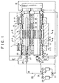
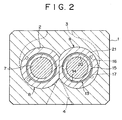
- FIG. 1 to FIG. 3 show a gear pump for carrying quantitative molten resins in a mixing granulating system.
- the gear pump has a block-like body 1.
- a glasses-like rotor housing hole 2 extends through and is formed in the body 1.
- a resin inlet 3 and outlet 4 are formed, through the rotor housing hole 2, on the both sides of the latter.
- a pair of rotors 5, 5 are housed in the rotor housing hole 2.
- the rotor 5 comprises gear parts 6 and shaft parts formed on both sides thereof.
- the both gear parts 6 are always meshed with each other.
- the shaft part 7 is supported rotatably by a journal bearing 8 fitted in the rotor housing hole 2.
- the bearing (8) is prevented from slipping out of the rotor housing hole 2 by a bearing retainer 10 secured to the body 1 by means of a bolt 9.
- a seal member 11 is secured to the bearing retainer 10. In the seal member 11 and the shaft part 7, the molten resins are prevented from flowing outside by means of a labyrinth seal.
- One end of the shaft part 7 of the rotor 5 is connected to a drive device 12.
- the rotor 5 is rotated and driven in a direction indicated by arrow of FIG. 3, and the molten resins are carried from the resin inlet 3 to the outlet 4.
- the gear pump is of a self-lubricating type, in which a par of the molten resins carried is supplied as lubricant for the bearing 8 and the shaft part 7.
- a well known construction for example, U.S. Pat. No. 5,292,237) can be employed.
- the seal member 11 is provided to prevent leakage of the molten resins outside used for lubrication of a bearing.
- the journal bearing 8 is formed internally with a cooling medium passage 13, and is constituted as a cooling bearing device.
- the cooling medium passage 13 is constituted by an annular space 14 formed internally of the bearing 8, and a partitioning wall 15 provided in the annular space 14.
- the partitioning wall 15 is provided spirally as shown in the peripheral developed view of FIG. 4.
- the cooling medium passage 13 comprising two spiral grooves is formed in the annular space 14.
- a cooling medium inlet 16 is formed at the end of one groove, and a cooling medium outlet 17 is formed at the end of the other groove.
- An inlet pipe 18 and an outlet pipe 19 extending through the bearing retainer 10 and the seal member 11 are connected to the cooling medium inlet 16 and outlet 17.
- the bearing 8 is constituted by integrally connecting an inner circumferential member 20 and an outer circumferential member 21.
- the cooling medium passage 13 is formed in a boundary between the inner circumferential member 20 and the outer circumferential member 21.
- the inner circumferential member 20 is formed in the outer circumferential surface 21 with an annular recess forming the annular space 14, and a spiral partitioning wall 15 shown in FIG. 14 is formed within the annular recess.
- Methods for integrating of the inner circumferential member 20 is formed in the outer circumferential surface 21 include welding, welding after shrinkage fitting and the like.
- the outer circumferential surface of the partitioning wall 15 is in contact with the inner circumferential surface of the outer circumferential member 21. That is, the annular space 14 is surrounded by the inner circumferential surface of the outer circumferential member 21 and the outer circumferential surface of the annular recess of the inner circumferential member 20, and the partitioning wall 15 is formed over the inner and outer circumferential surfaces.
- the partitioning wall formed over the inner and outer circumferential surfaces of the annular space 14 functions as a strengthening member. Accordingly, even if the annular space is made large, the lowering of the bearing strength can be compensated for.
- the shaft center part of the rotor 5 is bored with a hole 22 in an axial direction from one end thereof.
- a pipe 23 is inserted into the hole 22 through an annular clearance, which clearance serves as a cooling medium passage 24.
- the cooling medium passage is provided, at least, so as to correspond to the shaft part 7 of the rotor 5.
- a rotational joint 25 is provided on the end of the rotor 5, and the joint 25 is provided with a cooling medium inlet 26 and outlet 27.
- the inlet 26 is communicated with the cooling medium passage 24, and the outlet 27 is communicated with the interior of the pipe 23.
- the cooling medium supplied from the inlet 26 passes through the cooling medium passage 24, enters pipe 23 from the end opening of the pipe 23, and flows out of the outlet 27.
- a temperature adjusting medium supply device 28 as a cooling medium supply device is connected to the cooling medium inlet 16 and outlet 17 for cooling a bearing, and the inlet 26 and outlet 27 for cooling a rotor.
- a cooling medium supply source 29 and a heated medium supply source 30 are free to be switched by a three-way valve 31.
- the heated medium is supplied from the heated medium supply source 30 to the bearing 8 and the rotor 5 to thereby preheat and melt the cooled and solidified medium.
- the three-way valve 31 is switched to supply cooling medium from the cooling medium source 29 to cool the bearing 8 and at least the shaft part 7 of the rotor 5.
- Piping of the temperature adjusting medium supply device 28 is first connected from the three-way valve 31 to the inlet 26 for cooling a rotor, piping from the outlet 27 is connected to the inlet pipe 18 for cooling a bearing, and piping from the outlet pipe 19 for cooling a bearing is returned to the temperature adjusting medium supply device 28.
- the medium from the temperature adjusting medium supply device 28 first passes the rotor 5 and thereafter passes the bearing 8.
- the cooling medium temperature within the bearing 8 can be set to be higher than the cooling medium temperature within the rotor 5.
- the cooling temperature of the bearing 8 can be set to be higher than the rotor 5, shrinkage of the inside diameter of the bearing caused by excessive cooling is prevented. Accordingly, the reduction in the bearing clearance is prevented and the baking is prevented.
- the present invention is not limited to the above-described embodiment, but the cooling medium supply device of the bearing may be provided separately from that of the rotor, and the temperature control of the bearing 8 may be carried out independently of the rotor 5.
- the medium from the temperature adjusting medium supply device 28 is not limited to an arrangement that the cooling medium supply device 29 and the heated medium supply device 30 are free to be switched by the three-way valve 31, but there may be employed an arrangement that there is temperature adjusting range from cooling to heating, and the medium is supplied from a single supply source.
- the temperature adjusting medium is heated (preheated) by hot oil at 100 - 200° , and cooling is carried out by temperature control of a hot oil unit.
- the gear pump is not limited to one for carrying molten resin.
- the type of the cooling medium passage of the bearing 8 or the rotor 5 may be of the conventional type.
- the temperature adjusting medium supply device 28 may be of a type in which only the cooling medium is supplied.
- the bearing cooling device causes cooling media to flow into the interior of a journal bearing 8 for supporting a shaft part 7 by lubrication of high viscous fluid and the interior of the shaft part 7 to cool the shaft part 7 and the bearing 8.
- cooling medium temperature of the bearing 8 is set to be higher than cooling medium temperature of the shaft part 7. It is constituted so that the cooling medium passes the cooling medium passage and thereafter passes the cooling medium passage internally of the bearing.
- a heated medium supply device for supplying a heated medium to each cooling medium passage may be provided.
- the bearing cooling device is used suitably for a gear pump.
Landscapes
- Engineering & Computer Science (AREA)
- Mechanical Engineering (AREA)
- General Engineering & Computer Science (AREA)
- Physics & Mathematics (AREA)
- Thermal Sciences (AREA)
- Rotary Pumps (AREA)
- Mounting Of Bearings Or Others (AREA)
- Processing And Handling Of Plastics And Other Materials For Molding In General (AREA)
- Structures Of Non-Positive Displacement Pumps (AREA)
Claims (6)
- Dispositif de refroidissement de palier d'un palier à tourillon (8) destiné à supporter une partie d'arbre (7) par lubrification de fluide hautement visqueux, comprenant :un passage de milieu de refroidissement (13) fourni à l'intérieur dudit palier (8) ;un passage de milieu de refroidissement (24) fourni à l'intérieur de ladite partie d'arbre (7) ; etcaractérisé par
un dispositif d'alimentation en milieu de refroidissement (28) faisant passer un milieu de refroidissement vers ledit passage de milieu de refroidissement (24) fourni à l'intérieur de ladite partie d'arbre (7) et par la suite vers le passage de milieu de refroidissement (13) à l'intérieur dudit palier (8) pour régler la température du milieu de refroidissement dudit palier supérieure à celle de ladite partie d'arbre. - Dispositif de refroidissement de palier selon la revendication 1, dans lequel la tuyauterie du milieu de refroidissement est d'abord reliée à une entrée (26) pour refroidir ledit passage de milieu de refroidissement (24) fourni à l'intérieur de ladite partie d'arbre (7), puis est reliée depuis une sortie (27) jusqu'à un tuyau d'entrée (18) pour refroidir un passage de milieu de refroidissement (13) fourni à l'intérieur dudit palier (8) ;
- Dispositif de refroidissement de palier selon la revendication 1 ou 2, dans lequel, dans le dispositif d'alimentation en milieu de réglage de température (28), une source d'alimentation en milieu de refroidissement (29) et une source d'alimentation en milieu chauffé (30) sont libres d'être commutées à l'aide d'une vanne trois voies (31).
- Dispositif de refroidissement de palier selon la revendication 1, dans lequel ledit passage de milieu de refroidissement (13) fourni à l'intérieur dudit palier (8) est constitué d'un espace annulaire (14) formé à l'intérieur dudit palier (8) et d'une paroi de division (15) fournie en spirale dans ledit espace annulaire (14).
- Dispositif de refroidissement de palier selon la revendication 1, dans lequel ledit passage de milieu de refroidissement (13) fourni à l'intérieur dudit palier (8) comprend deux gorges en spirale.
- Pompe à engrenages munie dudit dispositif de refroidissement de palier selon la revendication 1.
Applications Claiming Priority (2)
| Application Number | Priority Date | Filing Date | Title |
|---|---|---|---|
| JP2000336653 | 2000-11-02 | ||
| JP2000336653A JP4056691B2 (ja) | 2000-11-02 | 2000-11-02 | 軸受冷却方法及び軸受冷却装置 |
Publications (3)
| Publication Number | Publication Date |
|---|---|
| EP1203894A2 EP1203894A2 (fr) | 2002-05-08 |
| EP1203894A3 EP1203894A3 (fr) | 2004-12-01 |
| EP1203894B1 true EP1203894B1 (fr) | 2007-02-07 |
Family
ID=18812167
Family Applications (1)
| Application Number | Title | Priority Date | Filing Date |
|---|---|---|---|
| EP01126026A Expired - Lifetime EP1203894B1 (fr) | 2000-11-02 | 2001-10-31 | Dispositif de refroidissement pour un palier |
Country Status (4)
| Country | Link |
|---|---|
| US (1) | US6575720B2 (fr) |
| EP (1) | EP1203894B1 (fr) |
| JP (1) | JP4056691B2 (fr) |
| DE (1) | DE60126459T2 (fr) |
Families Citing this family (9)
| Publication number | Priority date | Publication date | Assignee | Title |
|---|---|---|---|---|
| JP2007170341A (ja) * | 2005-12-26 | 2007-07-05 | Toyota Industries Corp | スクリュー式流体機械 |
| EP2796740B1 (fr) * | 2013-04-26 | 2017-03-22 | Siemens Aktiengesellschaft | Eolienne à action directe comprenant un dispositif de palier lisse |
| JP6052794B2 (ja) * | 2013-06-17 | 2016-12-27 | 株式会社神戸製鋼所 | ギヤポンプ及びギヤポンプの運転方法 |
| CN105697367A (zh) * | 2014-11-27 | 2016-06-22 | 北京化工大学 | 一种用于高粘度与热敏性物料加工的熔体齿轮泵 |
| GB201614327D0 (en) * | 2016-08-22 | 2016-10-05 | Rolls-Royce Controls And Data Services Ltd | Gear pump bearing |
| GB201614326D0 (en) * | 2016-08-22 | 2016-10-05 | Rolls-Royce Controls And Data Services Ltd | Gear pump bearing |
| CN107953261A (zh) * | 2017-12-26 | 2018-04-24 | 华辰精密装备(昆山)股份有限公司 | 高速磨削轧辊磨床主轴温控系统 |
| JP2019122167A (ja) * | 2018-01-09 | 2019-07-22 | 東洋電機製造株式会社 | 回転機 |
| CN108500199B (zh) * | 2018-04-02 | 2023-07-07 | 合肥市远大轴承锻造有限公司 | 一种用于抑制轴承锻件网状碳化物形成的智能控冷装置 |
Family Cites Families (9)
| Publication number | Priority date | Publication date | Assignee | Title |
|---|---|---|---|---|
| FR1142283A (fr) * | 1956-03-02 | 1957-09-16 | Wauquier Soc Nouv Ets | Procédé et dispositif pour refroidir les garnitures d'étanchéité d'arbres tournants de machine pour fluides liquides ou gazeux à haute température |
| US4948269A (en) * | 1989-07-11 | 1990-08-14 | Hamilton James T | Bearing temperature regulation and lubrication system |
| EP0458499B1 (fr) * | 1990-05-21 | 1997-07-23 | Makino Milling Machine Co. Ltd. | Appareil de refroidissement d'un palier de broche d'une machine |
| JPH0645135A (ja) | 1991-12-10 | 1994-02-18 | Taamo:Kk | 留め具 |
| JPH05209628A (ja) * | 1992-01-31 | 1993-08-20 | Ntn Corp | 軸受の潤滑装置とその制御方法 |
| JPH06134651A (ja) * | 1992-10-26 | 1994-05-17 | Nippon Seiko Kk | 温度制御アンダレース潤滑スピンドル装置 |
| EP0715078B1 (fr) | 1996-02-09 | 2001-11-07 | Maag Pump Systems Textron AG | Pompe à engrenages |
| JP3548330B2 (ja) * | 1996-04-09 | 2004-07-28 | エンシュウ株式会社 | 主軸のベアリング冷却装置 |
| JP3894991B2 (ja) * | 1996-11-05 | 2007-03-22 | 株式会社神戸製鋼所 | 溶融樹脂用ギアポンプとその運転方法 |
-
2000
- 2000-11-02 JP JP2000336653A patent/JP4056691B2/ja not_active Expired - Lifetime
-
2001
- 2001-10-31 EP EP01126026A patent/EP1203894B1/fr not_active Expired - Lifetime
- 2001-10-31 DE DE60126459T patent/DE60126459T2/de not_active Expired - Lifetime
- 2001-11-01 US US09/985,011 patent/US6575720B2/en not_active Expired - Lifetime
Also Published As
| Publication number | Publication date |
|---|---|
| DE60126459D1 (de) | 2007-03-22 |
| EP1203894A3 (fr) | 2004-12-01 |
| US6575720B2 (en) | 2003-06-10 |
| JP4056691B2 (ja) | 2008-03-05 |
| US20020051723A1 (en) | 2002-05-02 |
| DE60126459T2 (de) | 2007-11-29 |
| EP1203894A2 (fr) | 2002-05-08 |
| JP2002139062A (ja) | 2002-05-17 |
Similar Documents
| Publication | Publication Date | Title |
|---|---|---|
| JPH0246345B2 (fr) | ||
| US20130287328A1 (en) | Bearing arrangements and integrated cooling and/or heating devices and method for integrated heating or cooling | |
| US7651276B2 (en) | Bearing unit | |
| US11527939B2 (en) | Cooling arrangement for an electric machine, and electric machine | |
| US6575720B2 (en) | Bearing and shaft cooling device | |
| US20210010604A1 (en) | Rotary control valve | |
| US6524088B2 (en) | Gear pump having a bearing with a temperature adjusting medium passage | |
| US5924854A (en) | Gear pump channel arrangement for tempering media | |
| EP1126154B1 (fr) | Corps de papillon pour moteur à combustion et son procédé de fabrication | |
| US6299430B1 (en) | Cooling medium injection for pellet mill rollers | |
| EP0771682B1 (fr) | Genérateur de chaleur à fluide visqueux avec un élément de rotor allongé | |
| GB2121118A (en) | Cooled plain bearing | |
| JP2024541395A (ja) | 冷却インサートを有する遠心ポンプ | |
| CN100441919C (zh) | 行星齿轮箱 | |
| US5913306A (en) | Viscous fluid heater | |
| JP2021515144A (ja) | 電気機械およびギアボックスを備える構成および車両 | |
| AU703682B2 (en) | Continuous extrusion apparatus | |
| EP0844445B1 (fr) | Générateur de chaleur à fluide visqueux | |
| JP3895537B2 (ja) | ギヤポンプ | |
| US20050205359A1 (en) | Lube oil distribution apparatus | |
| JP3854058B2 (ja) | ギヤポンプ | |
| US5937797A (en) | Viscous fluid heater | |
| US5943991A (en) | Heater utilizing fluid frictional heat | |
| JPH0960712A (ja) | 歯車装置 | |
| JPH10141247A (ja) | 溶融樹脂用ギアポンプとその運転方法 |
Legal Events
| Date | Code | Title | Description |
|---|---|---|---|
| PUAI | Public reference made under article 153(3) epc to a published international application that has entered the european phase |
Free format text: ORIGINAL CODE: 0009012 |
|
| 17P | Request for examination filed |
Effective date: 20011031 |
|
| AK | Designated contracting states |
Kind code of ref document: A2 Designated state(s): AT BE CH CY DE DK ES FI FR GB GR IE IT LI LU MC NL PT SE TR |
|
| AX | Request for extension of the european patent |
Free format text: AL;LT;LV;MK;RO;SI |
|
| PUAL | Search report despatched |
Free format text: ORIGINAL CODE: 0009013 |
|
| AK | Designated contracting states |
Kind code of ref document: A3 Designated state(s): AT BE CH CY DE DK ES FI FR GB GR IE IT LI LU MC NL PT SE TR |
|
| AX | Request for extension of the european patent |
Extension state: AL LT LV MK RO SI |
|
| 17Q | First examination report despatched |
Effective date: 20050620 |
|
| AKX | Designation fees paid |
Designated state(s): CH DE LI |
|
| GRAP | Despatch of communication of intention to grant a patent |
Free format text: ORIGINAL CODE: EPIDOSNIGR1 |
|
| GRAS | Grant fee paid |
Free format text: ORIGINAL CODE: EPIDOSNIGR3 |
|
| GRAA | (expected) grant |
Free format text: ORIGINAL CODE: 0009210 |
|
| AK | Designated contracting states |
Kind code of ref document: B1 Designated state(s): CH DE LI |
|
| REG | Reference to a national code |
Ref country code: CH Ref legal event code: EP |
|
| REF | Corresponds to: |
Ref document number: 60126459 Country of ref document: DE Date of ref document: 20070322 Kind code of ref document: P |
|
| REG | Reference to a national code |
Ref country code: CH Ref legal event code: NV Representative=s name: E. BLUM UND CO. AG PATENT- UND MARKENANWAELTE VSP |
|
| PLBE | No opposition filed within time limit |
Free format text: ORIGINAL CODE: 0009261 |
|
| STAA | Information on the status of an ep patent application or granted ep patent |
Free format text: STATUS: NO OPPOSITION FILED WITHIN TIME LIMIT |
|
| 26N | No opposition filed |
Effective date: 20071108 |
|
| PGFP | Annual fee paid to national office [announced via postgrant information from national office to epo] |
Ref country code: CH Payment date: 20201015 Year of fee payment: 20 Ref country code: DE Payment date: 20201020 Year of fee payment: 20 |
|
| REG | Reference to a national code |
Ref country code: DE Ref legal event code: R071 Ref document number: 60126459 Country of ref document: DE |
|
| REG | Reference to a national code |
Ref country code: CH Ref legal event code: PL |