EP1203895A2 - Frein à disque actionné électromécaniquement avec frein de stationnement - Google Patents
Frein à disque actionné électromécaniquement avec frein de stationnement Download PDFInfo
- Publication number
- EP1203895A2 EP1203895A2 EP01124989A EP01124989A EP1203895A2 EP 1203895 A2 EP1203895 A2 EP 1203895A2 EP 01124989 A EP01124989 A EP 01124989A EP 01124989 A EP01124989 A EP 01124989A EP 1203895 A2 EP1203895 A2 EP 1203895A2
- Authority
- EP
- European Patent Office
- Prior art keywords
- gear
- rotor
- brake
- axis
- actuating element
- Prior art date
- Legal status (The legal status is an assumption and is not a legal conclusion. Google has not performed a legal analysis and makes no representation as to the accuracy of the status listed.)
- Withdrawn
Links
- 230000001960 triggered effect Effects 0.000 claims description 7
- 238000006073 displacement reaction Methods 0.000 claims description 2
- FWZTTZUKDVJDCM-CEJAUHOTSA-M disodium;(2r,3r,4s,5s,6r)-2-[(2s,3s,4s,5r)-3,4-dihydroxy-2,5-bis(hydroxymethyl)oxolan-2-yl]oxy-6-(hydroxymethyl)oxane-3,4,5-triol;iron(3+);oxygen(2-);hydroxide;trihydrate Chemical compound O.O.O.[OH-].[O-2].[O-2].[O-2].[O-2].[O-2].[O-2].[O-2].[O-2].[Na+].[Na+].[Fe+3].[Fe+3].[Fe+3].[Fe+3].[Fe+3].O[C@H]1[C@H](O)[C@@H](CO)O[C@@]1(CO)O[C@@H]1[C@H](O)[C@@H](O)[C@H](O)[C@@H](CO)O1 FWZTTZUKDVJDCM-CEJAUHOTSA-M 0.000 description 1
- 230000005611 electricity Effects 0.000 description 1
- 210000003746 feather Anatomy 0.000 description 1
- BASFCYQUMIYNBI-UHFFFAOYSA-N platinum Chemical compound [Pt] BASFCYQUMIYNBI-UHFFFAOYSA-N 0.000 description 1
Images

Classifications
-
- F—MECHANICAL ENGINEERING; LIGHTING; HEATING; WEAPONS; BLASTING
- F16—ENGINEERING ELEMENTS AND UNITS; GENERAL MEASURES FOR PRODUCING AND MAINTAINING EFFECTIVE FUNCTIONING OF MACHINES OR INSTALLATIONS; THERMAL INSULATION IN GENERAL
- F16D—COUPLINGS FOR TRANSMITTING ROTATION; CLUTCHES; BRAKES
- F16D65/00—Parts or details
- F16D65/14—Actuating mechanisms for brakes; Means for initiating operation at a predetermined position
- F16D65/16—Actuating mechanisms for brakes; Means for initiating operation at a predetermined position arranged in or on the brake
- F16D65/18—Actuating mechanisms for brakes; Means for initiating operation at a predetermined position arranged in or on the brake adapted for drawing members together, e.g. for disc brakes
-
- F—MECHANICAL ENGINEERING; LIGHTING; HEATING; WEAPONS; BLASTING
- F16—ENGINEERING ELEMENTS AND UNITS; GENERAL MEASURES FOR PRODUCING AND MAINTAINING EFFECTIVE FUNCTIONING OF MACHINES OR INSTALLATIONS; THERMAL INSULATION IN GENERAL
- F16D—COUPLINGS FOR TRANSMITTING ROTATION; CLUTCHES; BRAKES
- F16D66/00—Arrangements for monitoring working conditions, e.g. wear, temperature
- F16D2066/003—Position, angle or speed
-
- F—MECHANICAL ENGINEERING; LIGHTING; HEATING; WEAPONS; BLASTING
- F16—ENGINEERING ELEMENTS AND UNITS; GENERAL MEASURES FOR PRODUCING AND MAINTAINING EFFECTIVE FUNCTIONING OF MACHINES OR INSTALLATIONS; THERMAL INSULATION IN GENERAL
- F16D—COUPLINGS FOR TRANSMITTING ROTATION; CLUTCHES; BRAKES
- F16D66/00—Arrangements for monitoring working conditions, e.g. wear, temperature
- F16D2066/005—Force, torque, stress or strain
-
- F—MECHANICAL ENGINEERING; LIGHTING; HEATING; WEAPONS; BLASTING
- F16—ENGINEERING ELEMENTS AND UNITS; GENERAL MEASURES FOR PRODUCING AND MAINTAINING EFFECTIVE FUNCTIONING OF MACHINES OR INSTALLATIONS; THERMAL INSULATION IN GENERAL
- F16D—COUPLINGS FOR TRANSMITTING ROTATION; CLUTCHES; BRAKES
- F16D2121/00—Type of actuator operation force
- F16D2121/18—Electric or magnetic
- F16D2121/24—Electric or magnetic using motors
-
- F—MECHANICAL ENGINEERING; LIGHTING; HEATING; WEAPONS; BLASTING
- F16—ENGINEERING ELEMENTS AND UNITS; GENERAL MEASURES FOR PRODUCING AND MAINTAINING EFFECTIVE FUNCTIONING OF MACHINES OR INSTALLATIONS; THERMAL INSULATION IN GENERAL
- F16D—COUPLINGS FOR TRANSMITTING ROTATION; CLUTCHES; BRAKES
- F16D2125/00—Components of actuators
- F16D2125/18—Mechanical mechanisms
- F16D2125/20—Mechanical mechanisms converting rotation to linear movement or vice versa
- F16D2125/34—Mechanical mechanisms converting rotation to linear movement or vice versa acting in the direction of the axis of rotation
- F16D2125/40—Screw-and-nut
-
- F—MECHANICAL ENGINEERING; LIGHTING; HEATING; WEAPONS; BLASTING
- F16—ENGINEERING ELEMENTS AND UNITS; GENERAL MEASURES FOR PRODUCING AND MAINTAINING EFFECTIVE FUNCTIONING OF MACHINES OR INSTALLATIONS; THERMAL INSULATION IN GENERAL
- F16D—COUPLINGS FOR TRANSMITTING ROTATION; CLUTCHES; BRAKES
- F16D2125/00—Components of actuators
- F16D2125/18—Mechanical mechanisms
- F16D2125/44—Mechanical mechanisms transmitting rotation
- F16D2125/46—Rotating members in mutual engagement
- F16D2125/48—Rotating members in mutual engagement with parallel stationary axes, e.g. spur gears
-
- F—MECHANICAL ENGINEERING; LIGHTING; HEATING; WEAPONS; BLASTING
- F16—ENGINEERING ELEMENTS AND UNITS; GENERAL MEASURES FOR PRODUCING AND MAINTAINING EFFECTIVE FUNCTIONING OF MACHINES OR INSTALLATIONS; THERMAL INSULATION IN GENERAL
- F16D—COUPLINGS FOR TRANSMITTING ROTATION; CLUTCHES; BRAKES
- F16D2125/00—Components of actuators
- F16D2125/18—Mechanical mechanisms
- F16D2125/58—Mechanical mechanisms transmitting linear movement
- F16D2125/64—Levers
-
- F—MECHANICAL ENGINEERING; LIGHTING; HEATING; WEAPONS; BLASTING
- F16—ENGINEERING ELEMENTS AND UNITS; GENERAL MEASURES FOR PRODUCING AND MAINTAINING EFFECTIVE FUNCTIONING OF MACHINES OR INSTALLATIONS; THERMAL INSULATION IN GENERAL
- F16D—COUPLINGS FOR TRANSMITTING ROTATION; CLUTCHES; BRAKES
- F16D2127/00—Auxiliary mechanisms
- F16D2127/06—Locking mechanisms, e.g. acting on actuators, on release mechanisms or on force transmission mechanisms
-
- F—MECHANICAL ENGINEERING; LIGHTING; HEATING; WEAPONS; BLASTING
- F16—ENGINEERING ELEMENTS AND UNITS; GENERAL MEASURES FOR PRODUCING AND MAINTAINING EFFECTIVE FUNCTIONING OF MACHINES OR INSTALLATIONS; THERMAL INSULATION IN GENERAL
- F16D—COUPLINGS FOR TRANSMITTING ROTATION; CLUTCHES; BRAKES
- F16D2129/00—Type of operation source for auxiliary mechanisms
- F16D2129/06—Electric or magnetic
- F16D2129/08—Electromagnets
Definitions
- the invention relates to an electromechanically actuated Disc brake with a parking brake system.
- Such a disc brake especially for the Application in motor vehicles is suitable, for example disclosed in DE 197 11 851 A1.
- the disc brake has one Brake caliper and an electric motor, whose stator with the Brake caliper is firmly connected.
- the rotary movement of the rotor is transmitted to a motor shaft, which acts as a spindle nut is trained.
- One arranged in the spindle nut The rotation of the motor shaft turns it into a spindle Linear movement offset with respect to the brake caliper.
- the Spindle is connected to a brake piston that is attached to one Brake pad adjoins.
- the parking brake has a cone ring on, which is arranged axially displaceably on the motor shaft is.
- the conical ring leaves in a first axial position rotation of the motor shaft in both directions is unimpeded to.
- the is in a second axial position Cone ring engages with the motor shaft and rotates with it this, with a rotation of the motor shaft into a Direction of rotation causes the cone ring to engage with a locking ring that is fixed to the motor axis, where against a rotation of the motor shaft into the other Direction of rotation causes the engagement between the Motor shaft and the cone ring and between the locking ring and releases the cone ring.
- the invention has for its object a Electromechanically actuated disc brake with one Parking brake system to specify which compared to the state technology is more compact.
- an electrically operated Disc brake with a parking brake system the Disc brake has the following features:
- An electric motor the disc brake has a rotor which rotates around a first Axis is rotatably mounted on a brake caliper.
- On Actuator for moving a brake pad opposite the caliper is along a second axis slidably arranged, the second axis in Runs essentially parallel to the first axis and from the first axis is spaced.
- the disc brake has one Means for converting the rotary motion of the rotor into one Linear movement of the actuator on, this Means has a spur gear.
- the Parking brake system has an actuation mechanism and a trigger to trigger the actuating mechanism.
- the actuating mechanism is designed such that it for mechanically locking a gear of the Engage the spur gear between the teeth of the gear can.
- gear is also possible because with a spur gear, the teeth of the gears on Outside diameters are attached, and z. B. in contrast to Large parts of the gears of a planetary gear are accessible from the outside.
- the mechanical locking by intervening between the Teeth of a gear represents a safe and positive Locking is in contrast to a friction or positive locking.
- the parking brake system can be locked mechanically be constructed very simply.
- the Actuating mechanism for a rotatably mounted pawl Engage between the teeth of the gear.
- the The pawl can be released by a spring the parking brake system be kept away from the gear.
- the Trigger can be designed as an electric lifting magnet that the Lock pawl when driving the electric lifting magnet deflects the tensile force of the spring into the teeth of the gear.
- the Parking brake system is such that it is only in the Actuation of the trigger consumes electricity. In this case exists both in the "triggered state” and in the "Undeployed condition" of the parking brake system none Energy demand.
- the disc brake is not for that designed self-locking. This means that Actuator from a position that the Actuator takes on strong brakes at electric motor switched off and when not triggered Parking brake system shifts to a position that Actuator with weak or no braking occupies. After a braking operation, that moves Actuator automatically, i.e. without pressing the Electric motor, back in a state that one corresponds to weaker brakes or no brakes. there the gear turns in a first direction of rotation.
- the Pawl is arranged relative to the gear such that the first direction of rotation of the gear opposite to Direction of rotation of the pawl when the Actuation mechanism is. This locks the pawl between the teeth of the gear, and the torque of the Gear acts against the pawl, making the pawl even after the trigger has been switched off against the pulling force of the Spring when the parking brake system is triggered is held.
- the distance from the pawl bearing to The gear is smaller than the distance from the bearing Pawl to the end of the pawl that is in the gear intervenes.
- the disc brake is designed so that the torque on the pawl resulting from the torque of the Gear is larger than that acting in the opposite direction Torque on the pawl resulting from the pulling force the feather.
- the gear can be, for example, a rotor gear, which is on Rotor is arranged and is part of the spur gear.
- the means for converting the rotary motion of the rotor into one Linear movement of the actuator can be a first part a spindle gear or a motion gear exhibit.
- the actuator at least through a second part of the spindle gear or
- the actuator can a spindle nut or nut or a spindle or Have screw.
- the means to convert the rotary motion of the rotor in a linear movement of the actuating element in this case has a spindle gear, which on first part of the spindle gear or motion gear is arranged.
- the rotor gear engages, for example Spindle gear gear on.
- the Outside diameter of the rotor gear is smaller than that Outside diameter of the spindle gear.
- the parking brake system can be attached particularly easily when the gear into which the actuating mechanism engages, the spindle gear is because it is the larger Has outer diameter and therefore more accessible is.
- Spur gear at least a first intermediate gear and has a second intermediate gear.
- the number increases Intermediate wheels the space requirement of the disc brake.
- first intermediate gear and the second Intermediate gear are arranged on the same intermediate shaft.
- the torque of the first intermediate gear is increased transfer the second intermediate gear.
- points the first intermediate gear has a larger outer diameter than the second idler gear. In this case, this applies first intermediate gear into the rotor gear while the second intermediate gear in the spindle gear intervenes.
- the gear that is through the Actuating mechanism is mechanically locked, the first Intermediate gear.
- the electronics for actuating the trigger can be directly connected to an electronic control unit for the disc brake be grown.
- This control electronics controls the Electric motor, can be used to measure the signals of a force sensor Force the actuator on the brake disc exercises, and signals of an electric motor rotor position sensor evaluate and can regulate the disc brake.
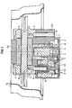
- a disc brake is provided the one designed as a floating caliper s and has a holder h.
- the holder h has one Seat pin f1 and another Caliper guide pin f2, along which the brake caliper s is slidably mounted (see Figure 1).
- the disc brake has an actuating unit, which in a cover d of the brake caliper s is mounted.
- the Actuating unit has an electric motor with a Rotor r and a stator st.
- a first part of the rotor is r mounted coaxially around the saddle guide pin f1 (see Figure 1).
- the second part of the Rotor r has a smaller outer diameter than that first part of the rotor r.
- On the second part of the rotor r is a Rotor gear zr attached, the smaller one Has outer diameter as the first part of the rotor r (see Figure 1).
- the rotor r is rotatably supported about a first axis a1.
- the first part of the rotor r is on a first bearing lr1 stored, while the second part of the rotor r on one second bearing lr2 is stored.
- the stator st of the electric motor is arranged around the rotor r and firmly connected to the brake caliper s.
- the actuating unit has an actuating element from a spindle nut m and a brake piston b.
- the Spindle nut m is firmly connected to the brake piston b.
- the Brake piston b is adjacent to a brake pad bb1.
- the Actuator serves to move the brake pad bb1 opposite the brake caliper s.
- the actuator is slidably arranged along a second axis a2.
- the second axis a2 runs essentially parallel to the first Axis a1 and is spaced from the first axis a1.
- the actuating unit also has a means for converting the rotational movement of the rotor r into a linear movement of the Actuator with respect to the brake caliper s.
- This Means consists of a spindle sp and one Helical gear unit to which the rotor gear zr belongs.
- the Helical gear also consists of a spindle gear zs, which is connected to the spindle sp, a first Intermediate gear z1 and a second intermediate gear z2.
- the first intermediate gear z1 and the second intermediate gear z2 in FIG. 1 is not shown.
- the first intermediate gear z1 and the second Intermediate gear z2 are on the same intermediate shaft between arranged (see Figure 2).
- the first intermediate gear z1 has a larger outer diameter than the second Intermediate gear z2 and as the rotor gear zr and meshes with the rotor gear zr on.
- the second intermediate gear z2 engages in the spindle gear zs.
- the brake caliper s has a projection on which one another brake pad bb2 adjoins.
- One to brake Brake disc bs is between the brake pad bb1 and the another brake pad bb2 arranged.
- the electric motor is controlled in such a way that due to the rotary motion of the rotor r the spindle nut m and the brake piston b moved towards the brake disc bs become.
- the brake pad bb1 also becomes direction Brake disc bs moves.
- the disc brake has one for controlling the electric motor Board p, which is mounted on a cover d (see Figure 1).
- a force sensor k for measuring the force that the Disc brake exerted on the brake disc bs is on the cover d mounts and adjoins a bearing lr3 of the spindle sp.
- the Force sensor k thus measures the force that the spindle sp exerts exerts the cover d, the force from the brake disc bs on the brake piston b, from the brake piston b to the Transfer spindle nut m and from there to spindle sp becomes.
- A is also connected to the cover d Electric motor rotor position encoder e, the rotation of the rotor r detected and leads to the board p. Electrical lines 1 to Stator st of the electric motor are connected to the board p.
- the bearings lr1, lr2, in which the rotor r is mounted, and the bearing lr3, in which the spindle sp is mounted, are on Lid d mounted.
- the intermediate shaft zw is on the cover d stored.
- the entire actuation unit is thus mounted on the cover.
- the spindle nut m with the brake piston b can around the spindle sp are screwed so that the spindle nut m and the Brake piston b also ultimately mounted on cover d are.
- the lid d is with the rest of the housing part g of Brake caliper s screwed.
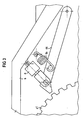
- the disc brake has a parking brake system that from a pawl sk, one on the brake caliper s Spring fe and a trigger a exists (see Figure 3).
- the Trigger a is designed as an electric lifting magnet and on Brake caliper s and at the non-supported end of the pawl sk attached. If the trigger a is not actuated, the spring will hold fe the pawl sk back from the first intermediate gear z1. If the trigger a is actuated, the pawl sk from Brake caliper s turned away against the spring force and grips with its end not supported on the brake caliper s between the teeth of the first intermediate gear z1.
- first Intermediate gear z1 acts on the first intermediate gear z1 a torque that a Rotation of the first intermediate gear z1 in one direction opposite to the direction of rotation of the pawl sk at Lock would cause the first intermediate gear z1 mechanically locked.
- the pawl sk can in this case even after trigger a is not turned off Return to the starting position. Only if at first Intermediate gear z1 has a torque that causes a rotation of the first intermediate gear with a direction of rotation that is the same the direction of rotation of the pawl sk is when locking, causes the pawl sk is released and returns due the tensile force of the spring fe back to its starting position back.
- the disc brake is designed so that the brake piston b starting from a position that the brake piston b at strong brakes, with the electric motor and if the parking brake system is not triggered, turn into a Position shifted that the brake piston b at weaker or takes no braking, so the first one Intermediate gear z1 during the above-mentioned displacement of the Brake piston b rotates in a first direction of rotation opposite to the direction of rotation of the pawl sk at Lock the first intermediate gear z1.
- the Disc brakes are therefore not designed to be self-locking.
Landscapes
- Engineering & Computer Science (AREA)
- General Engineering & Computer Science (AREA)
- Mechanical Engineering (AREA)
- Braking Arrangements (AREA)
Applications Claiming Priority (2)
| Application Number | Priority Date | Filing Date | Title |
|---|---|---|---|
| DE2000154471 DE10054471A1 (de) | 2000-11-03 | 2000-11-03 | Elektromechanisch betätigbare Scheibenbremse mit einer Feststellbremsanlage |
| DE10054471 | 2000-11-03 |
Publications (2)
| Publication Number | Publication Date |
|---|---|
| EP1203895A2 true EP1203895A2 (fr) | 2002-05-08 |
| EP1203895A3 EP1203895A3 (fr) | 2003-11-05 |
Family
ID=7662003
Family Applications (1)
| Application Number | Title | Priority Date | Filing Date |
|---|---|---|---|
| EP01124989A Withdrawn EP1203895A3 (fr) | 2000-11-03 | 2001-10-19 | Frein à disque actionné électromécaniquement avec frein de stationnement |
Country Status (2)
| Country | Link |
|---|---|
| EP (1) | EP1203895A3 (fr) |
| DE (1) | DE10054471A1 (fr) |
Cited By (7)
| Publication number | Priority date | Publication date | Assignee | Title |
|---|---|---|---|---|
| FR2846063A1 (fr) * | 2002-07-31 | 2004-04-23 | Bosch Gmbh Robert | Frein electromecanique |
| EP1460300A1 (fr) * | 2003-03-18 | 2004-09-22 | Continental Teves AG & Co. oHG | Procédé de mise en service des freins de stationnement pour freins à disque d'actionnement éléctromécanique. |
| WO2004099644A1 (fr) * | 2003-05-09 | 2004-11-18 | Lucas Automotive Gmbh | Frein automobile et procede d'actionnement d'un frein automobile |
| EP1460301A3 (fr) * | 2003-03-18 | 2006-06-07 | Continental Teves AG & Co. oHG | Frein à disque à commande électromécanique |
| EP1332301B1 (fr) * | 2000-11-06 | 2007-07-11 | Pacifica Group Technologies Pty Ltd | Module d'un frein a disque a commande electromecanique et frein a disque dote d'un module de ce type |
| CN110454527A (zh) * | 2019-08-01 | 2019-11-15 | 北京卓誉科技有限公司 | 一种超薄超轻断电保持机构 |
| DE102018129157A1 (de) * | 2018-11-20 | 2020-05-20 | Aat Alber Antriebstechnik Gmbh | Bremsanordnung für ein Laufrad eines Rollstuhls, Laufrad und Rollstuhl |
Families Citing this family (5)
| Publication number | Priority date | Publication date | Assignee | Title |
|---|---|---|---|---|
| DE10340250B4 (de) * | 2003-08-29 | 2016-02-25 | Continental Automotive Gmbh | Elektrische Parkbremse |
| ITMI20120220A1 (it) * | 2012-02-15 | 2013-08-16 | Freni Brembo Spa | Freno di stazionamento elettrico |
| DE102021110963B3 (de) | 2021-04-28 | 2022-12-01 | Schaeffler Technologies AG & Co. KG | Scheibenbremsanlage mit Parkbremsmodul für ein Fahrzeug sowie Fahrzeug mit der Scheibenbremsanlage |
| DE102024206950A1 (de) | 2023-08-01 | 2025-02-06 | Continental Automotive Technologies GmbH | Elektromagnetisch schaltbar definierte Feststelleinrichtung mit Modulaufbau, eine Kraftfahrzeugbremse umfassend die Feststelleinrichtung sowie Herstellungsverfahren dazu |
| DE102024208268A1 (de) | 2024-08-30 | 2026-03-05 | Robert Bosch Gesellschaft mit beschränkter Haftung | Elektromechanische Bremse mit Parkbremsaufnahme |
Family Cites Families (6)
| Publication number | Priority date | Publication date | Assignee | Title |
|---|---|---|---|---|
| DE19711851B4 (de) * | 1997-03-21 | 2005-09-22 | Continental Teves Ag & Co. Ohg | Bremsaktuator mit Feststellbremse für eine elektrische Bremsanlage |
| DE19732168C2 (de) * | 1997-07-25 | 2003-06-18 | Lucas Ind Plc | Hydraulische Fahrzeugbremse mit Feststelleinrichtung und Verfahren zum Betreiben derselben |
| DE19750420A1 (de) * | 1997-11-14 | 1999-05-20 | Bayerische Motoren Werke Ag | Elektrisch betätigbare Bremse für ein Kraftfahrzeug |
| DE19807328C2 (de) * | 1998-02-20 | 2003-08-28 | Lucas Ind Plc | Elektromechanisch betätigbare Scheibenbremse |
| JP4271852B2 (ja) * | 1998-03-05 | 2009-06-03 | コンティネンタル・テーベス・アクチエンゲゼルシヤフト・ウント・コンパニー・オッフェネ・ハンデルスゲゼルシヤフト | 電気機械的に操作可能なディスクブレーキ用の操作ユニット |
| DE19833304A1 (de) * | 1998-07-24 | 2000-02-10 | Daimler Chrysler Ag | Vorrichtung zur Bremsenbetätigung |
-
2000
- 2000-11-03 DE DE2000154471 patent/DE10054471A1/de not_active Ceased
-
2001
- 2001-10-19 EP EP01124989A patent/EP1203895A3/fr not_active Withdrawn
Cited By (9)
| Publication number | Priority date | Publication date | Assignee | Title |
|---|---|---|---|---|
| EP1332301B1 (fr) * | 2000-11-06 | 2007-07-11 | Pacifica Group Technologies Pty Ltd | Module d'un frein a disque a commande electromecanique et frein a disque dote d'un module de ce type |
| FR2846063A1 (fr) * | 2002-07-31 | 2004-04-23 | Bosch Gmbh Robert | Frein electromecanique |
| EP1460300A1 (fr) * | 2003-03-18 | 2004-09-22 | Continental Teves AG & Co. oHG | Procédé de mise en service des freins de stationnement pour freins à disque d'actionnement éléctromécanique. |
| EP1460301A3 (fr) * | 2003-03-18 | 2006-06-07 | Continental Teves AG & Co. oHG | Frein à disque à commande électromécanique |
| WO2004099644A1 (fr) * | 2003-05-09 | 2004-11-18 | Lucas Automotive Gmbh | Frein automobile et procede d'actionnement d'un frein automobile |
| US7316300B2 (en) | 2003-05-09 | 2008-01-08 | Lucas Automotive Gmbh | Vehicle brake and method for actuating a vehicle brake |
| DE102018129157A1 (de) * | 2018-11-20 | 2020-05-20 | Aat Alber Antriebstechnik Gmbh | Bremsanordnung für ein Laufrad eines Rollstuhls, Laufrad und Rollstuhl |
| CN110454527A (zh) * | 2019-08-01 | 2019-11-15 | 北京卓誉科技有限公司 | 一种超薄超轻断电保持机构 |
| CN110454527B (zh) * | 2019-08-01 | 2024-04-09 | 苏州卓誉电气技术有限公司 | 一种超薄超轻断电保持机构 |
Also Published As
| Publication number | Publication date |
|---|---|
| DE10054471A1 (de) | 2002-05-16 |
| EP1203895A3 (fr) | 2003-11-05 |
Similar Documents
| Publication | Publication Date | Title |
|---|---|---|
| DE68902940T2 (de) | Ein stellantrieb. | |
| EP0865977B1 (fr) | Frein à disque actionné par un moteur électrique | |
| DE102016113117B4 (de) | Elektrischer Stellantrieb und Stellgerät mit einem elektrischen Stellantrieb | |
| DE4407005C1 (de) | Fahrpedaleinrichtung | |
| EP1025372B1 (fr) | Systeme de freinage pour vehicule routier | |
| DE112019005759T5 (de) | Elektromechanisches aktuatorpaket zum betätigen einer bremsanordnung | |
| DE102009028568B4 (de) | Vorrichtung zur Blockierung eines linearen Stellantriebs | |
| EP1056960A1 (fr) | Frein a disque a commande electromagnetique | |
| EP0934473A1 (fr) | Dispositif de freinage | |
| EP1203895A2 (fr) | Frein à disque actionné électromécaniquement avec frein de stationnement | |
| EP1332300B1 (fr) | Frein a disque a commande electromagnetique | |
| EP1354147B1 (fr) | Frein de stationnement electromoteur, notamment pour un vehicule automobile | |
| EP2523835A1 (fr) | Entraînement pour l'actionnement d'un frein de stationnement | |
| EP0879365A1 (fr) | Dispositif pour actionner un frein sur roue d'un vehicule | |
| DE10244407A1 (de) | Elektrische Fahrzeugparkbremsvorrichtung | |
| DE102005059590A1 (de) | Trommelbremse | |
| DE102021203008A1 (de) | Betätigungseinrichtung für eine elektromechanisch betätigbare Kraftfahrzeugbremse | |
| DE4225158A1 (de) | Elektromaschinensystem | |
| DE60124308T2 (de) | Federbremsstellglied | |
| DE102011081011A1 (de) | Umschlingungsbremsvorrichtung für Planetengetriebe und Planetengetriebe mit Umschlingungsbremsvorrichtung | |
| DE202018103172U1 (de) | Motoranordnung | |
| EP1287272B1 (fr) | Frein de stationnement commande par un moteur electrique et destine notamment a un vehicule automobile | |
| DE10054938C2 (de) | Modul einer elektromechanisch betätigbaren Scheibenbremse und Scheibenbremse mit einem solchen Modul | |
| DE102022109506A1 (de) | Elektromechanische Bremse | |
| DE19744695A1 (de) | Stelleinrichtung, insbesondere für eine Kraftfahrzeug-Reibungskupplung |
Legal Events
| Date | Code | Title | Description |
|---|---|---|---|
| PUAI | Public reference made under article 153(3) epc to a published international application that has entered the european phase |
Free format text: ORIGINAL CODE: 0009012 |
|
| AK | Designated contracting states |
Kind code of ref document: A2 Designated state(s): AT BE CH CY DE DK ES FI FR GB GR IE IT LI LU MC NL PT SE TR |
|
| AX | Request for extension of the european patent |
Free format text: AL;LT;LV;MK;RO;SI |
|
| PUAL | Search report despatched |
Free format text: ORIGINAL CODE: 0009013 |
|
| AK | Designated contracting states |
Kind code of ref document: A3 Designated state(s): AT BE CH CY DE DK ES FI FR GB GR IE IT LI LU MC NL PT SE TR |
|
| AX | Request for extension of the european patent |
Extension state: AL LT LV MK RO SI |
|
| RIC1 | Information provided on ipc code assigned before grant |
Ipc: 7F 16D 65/14 B Ipc: 7F 16D 65/21 A |
|
| AKX | Designation fees paid | ||
| REG | Reference to a national code |
Ref country code: DE Ref legal event code: 8566 |
|
| STAA | Information on the status of an ep patent application or granted ep patent |
Free format text: STATUS: THE APPLICATION IS DEEMED TO BE WITHDRAWN |
|
| 18D | Application deemed to be withdrawn |
Effective date: 20040504 |