EP1203903A2 - Baureihe von Antriebssystemen und Gehäuseteil - Google Patents
Baureihe von Antriebssystemen und Gehäuseteil Download PDFInfo
- Publication number
- EP1203903A2 EP1203903A2 EP01123937A EP01123937A EP1203903A2 EP 1203903 A2 EP1203903 A2 EP 1203903A2 EP 01123937 A EP01123937 A EP 01123937A EP 01123937 A EP01123937 A EP 01123937A EP 1203903 A2 EP1203903 A2 EP 1203903A2
- Authority
- EP
- European Patent Office
- Prior art keywords
- sensor
- housing part
- sensor surface
- bearing
- borne noise
- Prior art date
- Legal status (The legal status is an assumption and is not a legal conclusion. Google has not performed a legal analysis and makes no representation as to the accuracy of the status listed.)
- Granted
Links
- 230000008719 thickening Effects 0.000 claims description 28
- 238000005553 drilling Methods 0.000 claims description 19
- 238000003754 machining Methods 0.000 claims description 16
- 230000005291 magnetic effect Effects 0.000 claims description 8
- 238000012545 processing Methods 0.000 claims description 8
- 238000013461 design Methods 0.000 claims description 7
- XEEYBQQBJWHFJM-UHFFFAOYSA-N Iron Chemical compound [Fe] XEEYBQQBJWHFJM-UHFFFAOYSA-N 0.000 claims description 6
- 230000005540 biological transmission Effects 0.000 claims description 6
- 239000000463 material Substances 0.000 claims description 5
- 238000003801 milling Methods 0.000 claims description 4
- XAGFODPZIPBFFR-UHFFFAOYSA-N aluminium Chemical compound [Al] XAGFODPZIPBFFR-UHFFFAOYSA-N 0.000 claims description 3
- 229910052782 aluminium Inorganic materials 0.000 claims description 3
- 238000005238 degreasing Methods 0.000 claims description 3
- 230000005294 ferromagnetic effect Effects 0.000 claims description 3
- 229910052742 iron Inorganic materials 0.000 claims description 3
- 238000007788 roughening Methods 0.000 claims description 3
- 238000005266 casting Methods 0.000 claims description 2
- 238000000227 grinding Methods 0.000 claims description 2
- 238000002372 labelling Methods 0.000 claims description 2
- 238000007639 printing Methods 0.000 claims description 2
- 238000007514 turning Methods 0.000 claims description 2
- 238000005520 cutting process Methods 0.000 claims 1
- 239000003973 paint Substances 0.000 claims 1
- 238000007790 scraping Methods 0.000 claims 1
- 230000008901 benefit Effects 0.000 description 29
- 238000005259 measurement Methods 0.000 description 12
- 238000012544 monitoring process Methods 0.000 description 9
- 239000000314 lubricant Substances 0.000 description 5
- 230000006378 damage Effects 0.000 description 4
- 229910001060 Gray iron Inorganic materials 0.000 description 3
- 230000002950 deficient Effects 0.000 description 3
- 238000000034 method Methods 0.000 description 3
- 238000003860 storage Methods 0.000 description 3
- 230000032683 aging Effects 0.000 description 2
- 238000010276 construction Methods 0.000 description 2
- 238000001514 detection method Methods 0.000 description 2
- 238000003745 diagnosis Methods 0.000 description 2
- 238000005516 engineering process Methods 0.000 description 2
- 238000010079 rubber tapping Methods 0.000 description 2
- 230000001133 acceleration Effects 0.000 description 1
- 239000000853 adhesive Substances 0.000 description 1
- 230000001070 adhesive effect Effects 0.000 description 1
- 238000009529 body temperature measurement Methods 0.000 description 1
- 238000004140 cleaning Methods 0.000 description 1
- 238000005260 corrosion Methods 0.000 description 1
- 230000007797 corrosion Effects 0.000 description 1
- 238000013016 damping Methods 0.000 description 1
- 238000011156 evaluation Methods 0.000 description 1
- 239000003302 ferromagnetic material Substances 0.000 description 1
- 238000009499 grossing Methods 0.000 description 1
- 238000003780 insertion Methods 0.000 description 1
- 230000037431 insertion Effects 0.000 description 1
- 238000009434 installation Methods 0.000 description 1
- 230000007774 longterm Effects 0.000 description 1
- 238000004519 manufacturing process Methods 0.000 description 1
- 230000005226 mechanical processes and functions Effects 0.000 description 1
- 230000003287 optical effect Effects 0.000 description 1
- 238000005457 optimization Methods 0.000 description 1
- 239000004540 pour-on Substances 0.000 description 1
- 230000008569 process Effects 0.000 description 1
- 238000005096 rolling process Methods 0.000 description 1
- 238000007789 sealing Methods 0.000 description 1
- 230000001360 synchronised effect Effects 0.000 description 1
- 230000007704 transition Effects 0.000 description 1
Images



Classifications
-
- F—MECHANICAL ENGINEERING; LIGHTING; HEATING; WEAPONS; BLASTING
- F16—ENGINEERING ELEMENTS AND UNITS; GENERAL MEASURES FOR PRODUCING AND MAINTAINING EFFECTIVE FUNCTIONING OF MACHINES OR INSTALLATIONS; THERMAL INSULATION IN GENERAL
- F16H—GEARING
- F16H57/00—General details of gearing
- F16H57/02—Gearboxes; Mounting gearing therein
- F16H57/033—Series gearboxes, e.g. gearboxes based on the same design being available in different sizes or gearboxes using a combination of several standardised units
-
- F—MECHANICAL ENGINEERING; LIGHTING; HEATING; WEAPONS; BLASTING
- F16—ENGINEERING ELEMENTS AND UNITS; GENERAL MEASURES FOR PRODUCING AND MAINTAINING EFFECTIVE FUNCTIONING OF MACHINES OR INSTALLATIONS; THERMAL INSULATION IN GENERAL
- F16H—GEARING
- F16H57/00—General details of gearing
- F16H57/01—Monitoring wear or stress of gearing elements, e.g. for triggering maintenance
- F16H2057/012—Monitoring wear or stress of gearing elements, e.g. for triggering maintenance of gearings
Definitions
- the invention relates to a series of drive systems and a housing part.
- the invention has for its object to structure-borne noise measurements on industrial Enable drive systems easily and inexpensively
- the task in the series of drive systems according to the claim 1 specified features and in the housing part according to the specified in claim 32 Features resolved.
- Essential features of the invention in the series of drive systems are that at least one housing part of at least one variant in the original form has at least one sensor surface that can be machined in such a way that a sensor can be removed after this machining .
- the series of drive systems comprises at least one size, which comprises at least one variant, the variant comprising at least one housing part.
- An essential advantage of the invention is that the shaped housing part is already shaped at the position of the sensor surface in such a way that a sensor surface can be quickly manufactured for the mounting of a sensor by simple machining. The series is therefore independent of the type of use of the housing part. For applications without a sensor, the molded housing part does not have to be machined. For applications with sensors, the molded housing part can be machined.
- the customer can therefore be supplied with a drive system without having to manufacture a special or specially made housing, especially as a special construction; machining of the sensor surface, for example including the introduction of a hole for a sensor, can be carried out in a simple and inexpensive manner.
- sensors in particular structure-borne noise sensors, only have sufficient signal quality if they are firmly installed.
- a housing part with a sensor surface can be designed that allows a suitable drilling depth. A minimum wall thickness must always be observed so that the housing function is maintained.
- structure-borne noise measurements on industrial Drive systems can advantageously be carried out simply and inexpensively. This also contributes It is essential that the sensor surface is not curved or even has corners.
- Another significant advantage of the invention is that the manufacturer of the housing part or the drive unit reference measurements on a sensor surface, i.e. at a defined position, can carry out and these measurements available to the customer as a comparison option can put. The customer can then take the measurements at the same location.
- Another important advantage of the invention is that the position of the sensor surface is not can be lost because the position is unchangeable, unlike, for example glued sensors of the prior art, the position of which is not exact after removal is reproducible. It should be noted that markings caused by dirt, oil, Corrosion, cleaning or the like can be lost.
- the housing part has a in the area of the sensor surface Thickening, especially thickening and / or elevation, for connection to at least one Sensor on.
- Thickening especially thickening and / or elevation, for connection to at least one Sensor on.
- the advantage here is that a thickening in the housing wall or on a Bearing point is provided within the series, so that none for introducing the sensor special variants are to be manufactured.
- the thickening is provided such that after insertion the minimum wall thickness is available in a hole for the sensor.
- the sensor is always there assigned to the series. For example, only one sensor can be used in a series, the has a maximum of one M8 hole. Smaller sensors can of course also be used.
- the housing part has at least one web or one elongated thickening, in particular for the passage of structure-borne noise, by the Sensor surface leads to a bearing point.
- the advantage here is that the structure-borne noise through the web or the thickening can be carried out very well.
- the housing part has at least one variant according to the Pour on a sensor surface that can be machined in such a way that after machining Mounting at least one sensor is feasible.
- the advantage here is that even with the Mold the wall of the housing part and webs and / or the thickening of the housing part in such a way are formed that after processing the sensor surface, the sensor can be installed and a has particularly good signal-to-noise ratio.
- the processing is either degreasing, roughening or at least one machining operation, such as milling, turning, grinding, drilling, filing, Sanding, tapping, planing.
- machining operation such as milling, turning, grinding, drilling, filing, Sanding, tapping, planing.
- the temperature stability Long-term stability, the mechanical stability during transport, blows, service, assembly or the same, the oil stability in the event of leakage and that compared to only magnetically mounted
- better signal quality i.e. better signal-to-noise ratio.
- screwing on advantageously a tread resistance can be achieved.
- the housing part in the area of the sensor surface is such thickened that a hole can be made so deep that a sensor can be screwed onto the Housing part can be mounted.
- the housing part in the area of the sensor surface can be such be thickened so that a hole can be made deeper than the greatest thickness of the housing part in the immediate vicinity of the area of the sensor surface.
- the sensor surface has means for centering, such as original ones Recess, for making a hole.
- means for centering such as original ones Recess
- the housing part in the area of the sensor surface is such magnetic and / or ferromagnetic and / or includes a magnetic part that a sensor is magnetically attracted to the housing part and / or can be fitted. It is an advantage that a quick detachable, quick and inexpensive assembly is also possible.
- the housing part has iron or is made of Aluminimumtikguss.
- the advantage here is that when using iron a magnetic Sensor can be attached because a magnetic attractive force can be formed and that at Use of aluminum in or on aluminum, especially on the inside of the A magnet can be attached to the housing part and has a ferromagnetic and / or permanent magnetic sensor attracts and holds.
- the housing part comprises at least one bearing point.
- the position of the sensor surface is such that the Bearing point to the sensor surface has a better signal line than from the bearing point to at least one other position on the outer surface of the housing part.
- the position of the sensor surface is such that a a better signal line is available from the first bearing point to the sensor surface than from other Bearing positions and / or positions of signal sources to the sensor surface.
- the better signal line is through a thickening, a Cast bridge or a special shape.
- the position of the sensor surface is such that from the bearing point there are no joints to the sensor surface.
- the advantage here is that structure-borne noise only is dampened little.
- the position of the sensor surface is such that signals from the first bearing point or a first group of bearing points are selectively detectable.
- Advantageous is that no mutual interference occurs.
- the sensor surface has means for identification or Designation on and / or is directly in with means of identification or designation Connection.
- the advantage here is that the sensor surface is clearly identifiable and the Measurement results can be assigned exactly. This is not just a constant online measurement executable, but also a measurement from time to time, taking place at certain time intervals Measurements carried out using a sensor mounted on the sensor surface and the measurement data obtained are compared with those obtained earlier on the same Sensor surface determined measurement data. It is also advantageous that the sensor for each such measurement can be dismantled and thus costs can be saved.
- the means for identification or designation at least one lettering, numbering, labeling, stamping, printing Nameplate and / or a non-contact identification system with surface wave sensors or with transponders.
- the advantage here is that even non-contact inexpensive passive systems can be used.
- the surface wave sensors or the This is because transponders are supplied with energy and need them when they are queried therefore no battery or the like.
- the senor surface has means for strain relief, in particular for a sensor connection cable.
- the advantage here is that the sensor surface also additional mechanical functions.
- the senor is a structure-borne noise sensor. It is an advantage that processes occurring directly at the warehouse, such as aging or destruction in a simple manner and can be detected without significant time delay.
- the senor is designed in such a way that structure-borne noise is also present at least one frequency from the range of 1 Hz to 10 MHz is detectable. Is an advantage doing that vibration sensors and structure-borne noise sensors from the ultrasonic range are usable. Depending on the frequency, there are various conditions and / or damage of the system observable.
- a first sensor is a structure-borne noise sensor and a second Sensor a thermal wire.
- a sensor surface several sensors, such as at least one structure-borne noise sensor, at least one thermal sensor and / or at least one oil condition sensor, mountable.
- the housing part has at least two mutually parallel and sensor surfaces arranged in such a way that the machining takes place simultaneously, in particular with a multi-spindle machine is executable.
- at least one sensor surface in one plane with foot surfaces of the transmission and is thus editable at the same time with the foot surfaces.
- sensor surfaces are in different variants and / or sizes are in the same geometric position so that for the different Variants and / or sizes have the same means for processing and means for reading Information can be used.
- the advantage here is that only one is cost-effective Device for reading information must be purchased.
- a foot surface of the transmission is at least as a sensor surface executed.
- the advantage here is that with a mounting direction of the gearbox, that is spatial Location of the gearbox, a foot surface unused and thus remains freely accessible, which makes this this spatial orientation can be used as a sensor surface without additional effort.
- a gear has foot surfaces for several spatial orientations.
- a foot surface such that it as Sensor surface is usable. For example, there are thickenings or webs or the like executed.
- a drilling depth for a threaded hole is Screw a sensor onto the sensor surface at least 15 mm.
- Sensors in particular according to the norm, can be fastened in such a stable manner that a good signal / noise ratio is achievable. With a smaller drilling depth, for example only 5 mm, this would only result a weak contact pressure and thus would occur at the transition from the sensor surface to the sensor the signal-to-noise ratio deteriorates greatly.
- the drilling depth is sufficient for a threaded hole Screwing a sensor onto the sensor surface of DIN 76.
- the advantage here is that the Thread on the sensor is fully loadable.
- the drilling depth is greater than at least 8 mm, in particular 14 mm, for a threaded hole for screwing a sensor onto the sensor surface.
- the advantage here is that resistance to walking is attainable.
- the housing part of a drive system comprising a bearing point
- the housing part has a sensor surface for mounting a sensor, the housing part having a greater thickness in the area of the sensor surface than the thickness which is determined by the strength theory while minimizing the material used and / or after carrying out industrial design.
- the advantage here is that the greater thickness enables the sensor to be mounted, for example by screwing, and / or enables a better signal line from the signal source to the sensor.
- the one or multiple sensors used or not are structure-borne noise sensors can be used, especially for monitoring bearing damage.
- the sensors are electrical with an electronic circuit, such as converters, bus or fieldbus devices Further processing and / or evaluation of the detected information connected.
- additionally usable sensors are thermal sensors and / or oil condition sensors.
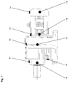
- Figure 1 shows a variant of a size of the Series according to the invention.
- the housing part is constructed such that the same Cast housing parts of the series can be used for variants with or without machined Sensor surfaces. So the housing part of the series can be attached without much additional effort changeable by sensors.
- the housing part is at the respective position of the sensor surfaces Pouring shaped so that it can be machined there. That is, the cast shape of the case the respective position has a flat sensor surface such that processing with machining is executable.
- the result of the machining is either one flat sensor surface with a surface quality that that for the functioning of the sensor required surface quality corresponds, or a sensor surface that a threaded hole for Screws in the sensor.
- Other sensors have an adhesive connection with the cast housing part required, the sensor surface being degreased and / or is sanded.
- FIG. 1 shows the positions for sensor surfaces 11-19 on a drive system, comprising Gearbox and engine. They are such that the conditions for a usable and sufficient signal-to-noise ratio of the sensor signal are available.
- a depository is a signal source for the structure-borne noise signal. This structure-borne noise spreads depending on the frequency mostly preferably along areas of higher material thickness.
- the positions are As close as possible to the bearing points as there are vibrations from gear meshing at these points and vibrations of the bearing itself are directed into the gear housing.
- the signal path from The structure-borne sound source to the sensor is as short as possible and without joints to the bearing point executed.
- Positions 11, 15 are close to the area of the bearing of the output shaft of the transmission.
- lateral forces or axial forces also occur, which are transmitted from the driven device to the transmission can act and burden the camp.
- the bearing can with excessive lateral forces and / or Axial forces get into defective operating states and / or age faster.
- a detection The structure-borne noise of this camp can therefore be used to monitor the aging Wear and tear.
- the signal-to-noise ratios obtained are depending on the quality of the structure-borne noise. Because positions 11, 15 are in close proximity of the output shaft bearing is a particularly good signal-to-noise ratio reachable. Positions 12 and 17 are in close proximity to another warehouse of the Gearbox, especially middle wall bearings. This also means that the signal-to-noise ratio is particularly good reachable for this camp.
- Positions 13 and 18 are in the immediate vicinity of the engine's output bearing.
- the Positions 14 and 19 are in the immediate vicinity of another bearing of the engine, the Electromagnetically actuated brake of the motor is arranged downstream, the brake comprises at least one driver toothing and a brake lining carrier.
- the brake comprises at least one driver toothing and a brake lining carrier.
- one side of the geared motor is inaccessible, for example the side Page on positions 15, 17, 18 and 19. Then there is another side accessible, including, for example, positions 11, 12, 13, 14.
- Position 16 is located directly close to an intermediate shaft bearing. So that's one too Monitoring of such a warehouse enables.
- one or more or even all positions are in each case usable for sensor surfaces. Depending on the application, all sensor surfaces are also included Sensors or some sensor areas remain without sensors. So that is Embodiment according to the invention flexibly adaptable to the respective application.
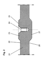
- Figure 2 shows an embodiment of a sensor surface according to the invention.
- the thickness of the wall of the Housing part 21 is determined on the one hand by minimal requirements of the strength theory and on the other hand by minimizing the material for reasons of saving weight and Costs. This results in thicknesses for industrial drives in the range from 0.1 kW to 1000 kW in the range of a few millimeters. With gray cast iron there is a wall thickness solely because of the casting process of at least 4mm necessary. With larger power to be transmitted and with larger to transmitting moments, a larger wall thickness is necessary, but by saving on Material is chosen as small as possible. For example, for a moment to be transmitted, 50 000 Nm 18mm necessary.
- a sensor to be mounted requires a threaded hole with a large one Drilling depth. It is possible, for example, when fastening with an M3 thread according to DIN 76 in Gray cast iron requires a drilling depth of 8mm.
- the sensors are suitable for industrial use a thread M8 is necessary, whereby a tread resistance can be achieved. That is, the sensor can be screwed so tightly that the structure-borne noise signal even under tread load, ie a Occurrence by one person, transferred sufficiently well from the sensor surface to the sensor becomes.
- a drilling depth of 18mm is required in accordance with DIN 76 in gray cast iron.
- a residual wall thickness of 2mm is necessary for reasons of tightness and strength.
- the series according to the invention has housing parts in the invention which are special Have thickening for mounting the sensors.
- Figure 2 shows an example of such Thickening.
- the inside 26 and outside 22 is with an elevation 23 outside and one Thickening 27 designed inside.
- the threaded bore 24 is made without the Housing part is drilled.
- the increase 23 has the sensor surface 25, which for flat Sensors is machined. Sensors with a cone connection receive the vibration signal the lowering of the threaded hole 24.
- FIG. 3 shows a sensor surface which, however, is additionally connected to the bearing point 38 by the web 39 connected is.
- the signal line from a bearing in bearing 38 to the sensor is thereby particularly good, since the bridge reduces the damping.
- the housing wall is not is drawn in, but is still there, because the bearing is built into the housing part.
- the signal line from the bearing point through this housing wall, which is thinner than the web, is worse than the signal line from the bearing point via the web to the sensor surface.
- This Sensor surface is therefore particularly well suited for monitoring the bearing in the storage area in particular 38.
- Sensors mounted in the sensor surface record the signal, ie the structure-borne noise, of the relevant bearing essentially selective. This means that signals from other signal sources, such as other camps with bearings, are no longer or only difficult to detect, especially one have poor signal-to-noise ratio.
- FIG. 4 shows a shaft 41 which is mounted in a housing part 44 by means of a bearing 42.
- the bearing in turn represents a signal source.
- the bearing point is curved on the outside and has one conical outer surface.
- the sensor surface 43 is flat and positioned at the bearing point. So is the sensor surface 43 is already implemented in the cast, that is to say the molded, housing part 44. In these Sensor surface 43 is then tapped with a large drilling depth, the Drilling depth is greater than the thickness of the bearing. A web is at this position of the sensor surface 43 not necessary because the sensor surface 43 is attached directly to the bearing point.
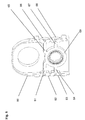
- Figure 5 shows a sectional view of the housing 51 of a parallel shaft gear.
- An example is one Provide sensor surface with web 58.
- the sensor surface is in the wall 54. It consists of the raised sensor surface 55, the threaded bore 56, the thickening 59 and the web 58, the the bearing 53 is directly connected.
- Embodiments according to the invention also include a sensor in a thickening of the wall can be mounted on a housing part so that there is direct contact with the lubricant.
- the drive system being filled with such a sufficient amount of lubricant and in its spatial orientation is used so that the lubricant in the Interior of the housing part protruding sensor and a signal line from the Signal source to the sensor via the lubricant is present, in particular also during operation, that is with rotating shafts and gears.
- vibrations thus come from an engaged, in the toothing not shown in FIG. 5 via the shaft 57 and the bearing 52 onto the bearing point 53. Vibrations that occur in the bearing 52 as a result of rolling processes also reach the Bearing 53. Such vibrations are then essentially in one by the web 58 5, not shown sensor supplied, which is screwed into the threaded bore 56.
- the threaded bore 56 and / or 55 adapters attached to the sensor surface each of which is used to connect a sensor, for example with quick release for diagnosis with handheld devices.
- the senor is on the sensor surface 55 glued.
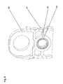
- FIG. 6 shows a housing 60 which not only has webs 64, 67 which lead to the shortest route Lead signal source, but also diverting webs 61, 65 that lead to locations at the bearing 69th cause a stronger signal source when suitably oriented transverse forces occur on the shaft represent.
- the webs 64, 67 and the redirecting webs 61, 65 lead the signal to the Sensor areas 62, 63, 66, 68.
- FIG. 7 shows a housing 70 which has a bearing point 71 on which thickened portions are formed are attached that the sensor surfaces 72, 75, 76 can be generated by machining.
- the Sensor surfaces are therefore positioned directly on the signal source and the web is in the storage location and the thickening integrated. Only the sensor surface 74 is connected to the bearing point via a web 73 connected because an adjacent bearing eye prevents the mounting space for the sensor.
- FIG. 8 shows a for a further exemplary embodiment according to the invention Temperature monitoring of the bearing by means of a thermal sensor that is designed for a Temperature measurement is introduced at the end of the web bore 82.
- the web bore 82 ends briefly in front of the depository 83.
- the web bore extends to the bearing seat the bearing 83 through, so allows direct contact of the thermal sensor with the Camp.
- the thermal sensor is designed in such a way that the sealing function is fulfilled.
- the sensor surface 81 is also covered with a Groove provided. Thereby, a thermal wire is also applied when the vibration sensor is glued on led outside.
- the web bore 82 is also of this type executable that it runs past the threaded hole.
- not only one sensor surface is on Housing part attached but there are one or on different sides of the housing part several sensor surfaces attached.
- every spatial orientation of the drive unit always have a sensor surface accessible and / or usable for mounting of a sensor.
- the sensors are simple can be attached because there are no corners, edges or curvatures.
- the customer has to do not worry where he has the best possible positions for attaching the sensor surfaces finds, but the positions are already set by the manufacturer and the housing part is already appropriately constructed, executed and prepared, especially by additional bridges and / or thickenings, which have an improved signal line and thus an improved signal quality, a good signal-to-noise ratio.
- the areas are already like this explained that processing is possible at all, in particular even quickly and easily.
- the positions for sensor surfaces executed by the manufacturer are at least in the invention set at optimal locations, with most of these locations at all in the prior art would not be usable, for example because the wall of the housing is too thin at these points or there is poor signal line to these locations.
Landscapes
- Engineering & Computer Science (AREA)
- General Engineering & Computer Science (AREA)
- Mechanical Engineering (AREA)
- Input Circuits Of Receivers And Coupling Of Receivers And Audio Equipment (AREA)
- Brushes (AREA)
- Coupling Device And Connection With Printed Circuit (AREA)
- Details Of Connecting Devices For Male And Female Coupling (AREA)
- Portable Nailing Machines And Staplers (AREA)
- Cylinder Crankcases Of Internal Combustion Engines (AREA)
Abstract
Description
Wesentliche Merkmale der Erfindung bei dem Gehäuseteil eines Antriebssystems, wobei das Gehäuseteil eine Lagerstelle umfasst, sind, dass das Gehäuseteil eine Sensorfläche zum Anmontieren eines Sensors aufweist, wobei das Gehäuseteil im Bereich der Sensorfläche eine größere Dicke aufweist als die Dicke, die sich nach der Festigkeitslehre unter Minimierung des eingesetzten Materials und/oder nach Ausführen von Industrie-Design ergibt. Von Vorteil ist dabei, dass die größere Dicke ein Anmontieren des Sensors, beispielsweise durch Anschrauben, ermöglicht und/oder eine bessere Signalleitung von der Signalquelle zum Sensor ermöglicht.
- 11,12,13,14,15,16,17,18,19
- Positionen für Sensorflächen
- 21, 31
- Gehäuseteil
- 22, 32
- Außenseite
- 23, 33
- Erhöhung
- 24, 34
- Gewindebohrung
- 25, 35
- Sensorfläche
- 26, 36
- Innenseite
- 27, 37
- Aufdickung
- 38
- Lagerstelle
- 39
- Steg
- 41
- Welle
- 42
- Lager
- 43
- Sensorfläche
- 44
- Gehäuseteil
- 51
- Gehäuse
- 52
- Lager
- 53
- Lagerstelle
- 54
- Wand
- 55
- Sensorfläche
- 56
- Gewindebohrung
- 57
- Welle
- 58
- Steg
- 59
- Aufdickung
- 60
- Gehäuse
- 61, 65
- Umleitender Steg
- 62, 63, 66, 68
- Sensorfläche
- 64, 67
- Steg
- 69
- Lagerstelle
- 70
- Gehäuse
- 71
- Lagerstelle
- 72, 74, 75, 76
- Sensorfläche
- 73
- Steg
- 80
- Gehäuse
- 81
- Sensorfläche
- 82
- Stegbohrung
- 83
- Lagerstelle
- die Art des Getriebes, beispielsweise mindestens eine Stirnradgetriebestufe, eine Planetengetriebestufe, eine Spiroplangetriebestufe, eine Verstellgetriebestufe, eine Winkelgetriebestufe, eine Kegelgetriebestufe, die Anzahi und Arten der Stufen, die Verzahnungsparameter, die geometrischen Daten und Abmessungen,
- und/oder die Art des Motors, beispielsweise einen Bremsmotor, einen Motor ohne Bremse, einen Reluktanzmotor, einen Synchronmotor, einen Asynchronmotor.
Claims (10)
- Baureihe von Antriebssystemen,
wobei die Baureihe mindestens eine Baugröße umfasst, die mindestens eine Variante umfasst,
wobei die Variante jeweils mindestens ein Gehäuseteil umfasst,
dadurch gekennzeichnet, dass
mindestens ein Gehäuseteil mindestens einer Variante in der Urform mindestens eine Sensorfläche aufweist, die derart bearbeitbar ist, dass nach dieser Bearbeitung ein Anmontieren eines Sensors ausführbar ist. - Baureihe nach mindesten einem der vorangegangenen Ansprüche,
dadurch gekennzeichnet, dass
das Gehäuseteil im Bereich der Sensorfläche eine Verdickung, insbesondere Aufdickung und/oder Erhöhung, zum Verbinden mit mindestens einem Sensor aufweist. - Baureihe nach mindesten einem der vorangegangenen Ansprüche,
dadurch gekennzeichnet, dass
das Gehäuseteil mindestens einen Steg oder eine längliche Verdickung, insbesondere zum Durchleiten von Körperschall, aufweist, die von der Sensorfläche zu einer Lagerstelle führt. - Baureihe nach mindesten einem der vorangegangenen Ansprüche,
dadurch gekennzeichnet, dass
die Antriebssysteme Getriebe, Motoren, Generatoren, Getriebemotoren, Ventilatoren, Pumpen,
wobei die Getriebe Stirnrad-, Zyklo-, Kegelrad-, Schnecken- und/oder Verstellgetriebestufen umfassen. - Baureihe nach mindesten einem der vorangegangenen Ansprüche,
dadurch gekennzeichnet, dassdas Gehäuseteil mindestens einer Variante nach dem Gießen eine Sensorfläche aufweist, die derart bearbeitbar ist, dass nach der Bearbeitung ein Anmontieren mindestens eines Sensors ausführbar istund/oder dass
das Bearbeiten ein Entfetten, ein Lackentfernen, ein Aufrauhen und/oder mindestens eine spanende Bearbeitung ist, wie Fräsen, Drehen, Schleifen, Bohren, Feilen, Abschmirgeln, Gewindeschneiden, Hobeln, Schabenund/oder dass
die Sensorfläche über das Gehäuseteil derart hinausstehend ist, dass sie mit einem Werkzeug, insbesondere einem Fräser, bearbeitbar ist, der größer ist als die Sensorflächeund/oder dass
die Sensorfläche in einem planen Bereich des Gehäuseteils liegt oder ins Gehäuseteil derart vertieft liegt, dass sie mit einem Werkzeug, insbesondere einem Fräser oder einem Flachsenker, bearbeitbar istund/oder dass
die jeweilige Sensorfläche eine derartige Größe und/oder einen derartigen Durchmesser aufweist, dass ein Sensor mittels Anschrauben an das Gehäuseteil anmontierbar ist.und/oder dass
das Gehäuseteil im Bereich der Sensorfläche derart verdickt ist, dass eine Bohrung derart tief ausführbar ist, dass ein Sensor mittels Anschrauben an das Gehäuseteil anmontierbar ist.und/oder dass
das Gehäuseteil im Bereich der Sensorfläche derart verdickt ist, dass eine Bohrung tiefer ausführbar ist als die größte Dicke des Gehäuseteils in unmittelbarer Umgebung des Bereiches der Sensorflächeund/oder dass
die Sensorfläche Mittel zur Zentrierung, wie urgeformte Vertiefung, für das Anbringen einer Bohrung aufweist.und/oder dass
das Gehäuseteil im Bereich der Sensorfläche derart magnetisch und/oder ferromagnetisch ist und/oder ein magnetisches Teil umfasst, dass ein Sensor magnetisch an das Gehäuseteil angezogen wird und/oder anmontierbar istund/oder dass
das Gehäuseteil Eisen aufweist oder aus Aluminimumdruckguss ist. - Baureihe nach mindesten einem der vorangegangenen Ansprüche,
dadurch gekennzeichnet, dassdas Gehäuseteil mindestens eine Lagerstelle umfasstund/oder dass
die Position der Sensorfläche derart ist, dass vom Lagerstelle zur Sensorfläche eine bessere Signalleitung vorhanden ist als vom Lagerstelle zu mindestens einer anderen Position an der Außenfläche des Gehäuseteilsund/oder dass
die Position der Sensorfläche derart ist, dass von einer ersten Lagerstelle zur Sensorfläche eine bessere Signalleitung vorhanden ist als von weiteren Lagerstellen und/oder Positionen von Signalquellen zur Sensorflächeund/oder dass
die bessere Signalleitung durch eine Verdickung, einen Gusssteg oder eine besondere Formung bewirkt istund/oder dass
die Position der Sensorfläche derart ist, dass von der Lagerstelle zur Sensorfläche keine Fügestellen vorhanden sindund/oder dass
die Position der Sensorfläche derart ist, dass Signale der ersten Lagerstelle oder einer ersten Gruppe von Lagerstellen selektiv detektierbar sindund/oder dass
die Sensorfläche Mittel zur Identifikation oder Bezeichnung aufweist und/oder mit Mitteln zur Identifikation oder Bezeichnung direkt in Verbindung stehtund/oder dass
die Mittel zur Identifikation oder Bezeichnung mindestens eine Beschriftung, eine Nummerierung, Etikettierung, Stempelung, Bedruckung, ein Typenschild und/oder ein berührungsloses Identifikationssystem mit Oberflächenwellensensoren oder mit Transpondern sind. - Baureihe nach mindesten einem der vorangegangenen Ansprüche,
dadurch gekennzeichnet, dass
die Fläche Mittel zur Zugentlastung, insbesondere für ein Sensoranschlusskabel, aufweist. - Baureihe nach mindesten einem der vorangegangenen Ansprüche,
dadurch gekennzeichnet, dassder Sensor ein Körperschallsensor istund/oder dass
der Sensor derart gestaltet ist, dass Körperschall mit mindestens einer Frequenz aus dem Bereich von 1 Hz bis 10 MHz detektierbar ist. - Baureihe nach mindesten einem der vorangegangenen Ansprüche,
dadurch gekennzeichnet, dassan einer Sensorfläche mehrere Sensoren, wie mindestens ein Körperschallsensor, mindestens ein Thermosensor und/oder mindestens ein Ölzustandssensor, anmontierbar sindund/oder dass
ein erster Sensor ein Körperschallsensor ist und ein zweiter Sensor ein Thermodraht istund/oder dass
das Gehäuseteil mindestens zwei, zueinander parallele und derart angeordnete Sensorflächen aufweist, dass die Bearbeitung gleichzeitig, insbesondere mit einer Mehrspindelmaschine, ausführbar istund/oder dass
Sensorflächen bei verschiedenen Varianten und/oder Baugrößen sich derart an derselben geometrischen Position befinden, dass für die verschiedenen Varianten und/oder Baugrößen dieselben Mittel zur Bearbeitung und Mittel zum Ablesen von Informationen verwendbar sindund/oder dass
mindestens eine Sensorfläche in einer Ebene mit Fußflächen des Getriebes liegt und somit gleichzeitig mit den Fußflächen bearbeitbar istund/oder dass
mindestens eine Fußfläche als Sensorfläche des Getriebes ausgeführt istund/oder dass
die Bohrtiefe für eine Gewindebohrung zum Anschrauben eines Sensors an der Sensorfläche der DIN 76 genügtund/oder dass
die Bohrtiefe größer ist als 14 mm für eine Gewindebohrung zum Anschrauben eines Sensors an der Sensorfläche. - Gehäuseteil eines Antriebssystems,
wobei das Gehäuseteil eine Lagerstelle umfasst
dadurch gekennzeichnet, dass
das Gehäuseteil eine Sensorfläche zum Anmontieren eines Sensors aufweist,
wobei das Gehäuseteil im Bereich der Sensorfläche eine größere Dicke aufweist als die Dicke, die sich nach der Festigkeitslehre unter Minimierung des eingesetzten Materials und/oder nach Ausführen von Industrie-Design ergibt.
Applications Claiming Priority (2)
| Application Number | Priority Date | Filing Date | Title |
|---|---|---|---|
| DE10059503 | 2000-11-03 | ||
| DE10059503A DE10059503A1 (de) | 2000-11-03 | 2000-11-03 | Baureihe von Antriebssystemen und Gehäuseteil |
Publications (3)
| Publication Number | Publication Date |
|---|---|
| EP1203903A2 true EP1203903A2 (de) | 2002-05-08 |
| EP1203903A3 EP1203903A3 (de) | 2004-08-25 |
| EP1203903B1 EP1203903B1 (de) | 2008-07-23 |
Family
ID=7665263
Family Applications (1)
| Application Number | Title | Priority Date | Filing Date |
|---|---|---|---|
| EP01123937A Expired - Lifetime EP1203903B1 (de) | 2000-11-03 | 2001-10-08 | Baureihe von Antriebssystemen und Gehäuseteil |
Country Status (3)
| Country | Link |
|---|---|
| EP (1) | EP1203903B1 (de) |
| AT (1) | ATE402359T1 (de) |
| DE (2) | DE10059503A1 (de) |
Cited By (7)
| Publication number | Priority date | Publication date | Assignee | Title |
|---|---|---|---|---|
| WO2007025527A1 (de) * | 2005-08-31 | 2007-03-08 | Ksm Castings Gmbh | Aus einem getriebe- und einem kupplungsgehäuse zusammengesetztes aggregat |
| WO2007025526A1 (de) * | 2005-08-31 | 2007-03-08 | Ksm Castings Gmbh | Aus einem getriebe- und einem kupplungsgehäuse zusammengesetztes aggregat |
| WO2009036874A3 (de) * | 2007-09-13 | 2009-07-23 | Sew Eurodrive Gmbh & Co | Antriebseinheit, verfahren zur wartung von komponenten, verfahren zur identifizierung der komponenten, verfahren zur herstellung und baukasten mit komponenten für eine antriebseinheit |
| EP2255108B1 (de) * | 2008-03-06 | 2013-10-23 | SEW-Eurodrive GmbH & Co | System mit getriebe |
| WO2017127008A1 (en) * | 2016-01-20 | 2017-07-27 | Scania Cv Ab | A system and a method for monitoring a gearbox |
| CN113386817A (zh) * | 2021-08-03 | 2021-09-14 | 北京市地铁运营有限公司 | 轴箱复合传感器的安装垫片及轴箱 |
| US12338887B2 (en) | 2020-06-19 | 2025-06-24 | Flender Gmbh | Scalable transmission housing, and housing series |
Families Citing this family (6)
| Publication number | Priority date | Publication date | Assignee | Title |
|---|---|---|---|---|
| DE102011119356B4 (de) * | 2011-11-25 | 2020-07-09 | Sew-Eurodrive Gmbh & Co Kg | System zur Prüfung von Merkmalen an einem Prüfobjekt, ebensolches System, das zur Prüfung von Merkmalen an aufeinander folgend hergestellten Prüfobjekten, also Produkten verwendet wird und Verfahren zum Betreiben eines solchen Systems |
| DE102011119350B4 (de) * | 2011-11-25 | 2020-07-09 | Sew-Eurodrive Gmbh & Co Kg | System zur Prüfung von Merkmalen an Prüfobjekten und Verfahren zum Betreiben eines Systems |
| DE102019103781A1 (de) * | 2019-02-14 | 2020-08-20 | Wittenstein Se | Adapterplatte |
| US11787286B2 (en) * | 2019-12-20 | 2023-10-17 | Deere & Company | Axle assembly with torque sensor |
| DE102024000136A1 (de) | 2023-02-01 | 2024-08-01 | Sew-Eurodrive Gmbh & Co Kg | Getriebe mit Gehäuseteil |
| DE102024120174A1 (de) | 2023-08-24 | 2025-02-27 | Sew-Eurodrive Gmbh & Co Kg | Getriebe mit einem Gehäuseteil und einem mit dem Gehäuseteil verbundenen Lagergehäuse |
Family Cites Families (6)
| Publication number | Priority date | Publication date | Assignee | Title |
|---|---|---|---|---|
| JPS59164938A (ja) * | 1983-03-09 | 1984-09-18 | Mitsubishi Electric Corp | 歯車異常音検出装置 |
| JPS60168946A (ja) * | 1984-02-10 | 1985-09-02 | Aisin Warner Ltd | 変速機の電子式車速センサロ−タ |
| US4586401A (en) * | 1984-04-16 | 1986-05-06 | Chrysler Corporation | Transmission speed sensor arrangement |
| EP0397309A2 (de) * | 1989-05-12 | 1990-11-14 | The Timken Company | Lagervorrichtung |
| FR2734873B1 (fr) * | 1995-05-30 | 1997-07-11 | Skf France | Roulement equipe d'un dispositif integre de detection de la vitesse de rotation |
| US6435724B1 (en) * | 1997-07-30 | 2002-08-20 | Rockwell International Corporation | Transmission output bearings with intermediate speedometer sensor |
-
2000
- 2000-11-03 DE DE10059503A patent/DE10059503A1/de not_active Withdrawn
-
2001
- 2001-10-08 AT AT01123937T patent/ATE402359T1/de not_active IP Right Cessation
- 2001-10-08 EP EP01123937A patent/EP1203903B1/de not_active Expired - Lifetime
- 2001-10-08 DE DE50114145T patent/DE50114145D1/de not_active Expired - Lifetime
Non-Patent Citations (2)
| Title |
|---|
| Veröffentlichung Antriebstechnik 37 (1999) Nr.6 Seite 80-83 |
| Veröffentlichung Antriebstechnik 38 (1999) Nr.1 Seite 51-55 |
Cited By (8)
| Publication number | Priority date | Publication date | Assignee | Title |
|---|---|---|---|---|
| WO2007025527A1 (de) * | 2005-08-31 | 2007-03-08 | Ksm Castings Gmbh | Aus einem getriebe- und einem kupplungsgehäuse zusammengesetztes aggregat |
| WO2007025526A1 (de) * | 2005-08-31 | 2007-03-08 | Ksm Castings Gmbh | Aus einem getriebe- und einem kupplungsgehäuse zusammengesetztes aggregat |
| WO2009036874A3 (de) * | 2007-09-13 | 2009-07-23 | Sew Eurodrive Gmbh & Co | Antriebseinheit, verfahren zur wartung von komponenten, verfahren zur identifizierung der komponenten, verfahren zur herstellung und baukasten mit komponenten für eine antriebseinheit |
| EP2255108B1 (de) * | 2008-03-06 | 2013-10-23 | SEW-Eurodrive GmbH & Co | System mit getriebe |
| US9958052B2 (en) | 2008-03-06 | 2018-05-01 | Sew-Eurodrive Gmbh & Co. Kg | System having a gear unit |
| WO2017127008A1 (en) * | 2016-01-20 | 2017-07-27 | Scania Cv Ab | A system and a method for monitoring a gearbox |
| US12338887B2 (en) | 2020-06-19 | 2025-06-24 | Flender Gmbh | Scalable transmission housing, and housing series |
| CN113386817A (zh) * | 2021-08-03 | 2021-09-14 | 北京市地铁运营有限公司 | 轴箱复合传感器的安装垫片及轴箱 |
Also Published As
| Publication number | Publication date |
|---|---|
| DE50114145D1 (de) | 2008-09-04 |
| EP1203903A3 (de) | 2004-08-25 |
| ATE402359T1 (de) | 2008-08-15 |
| DE10059503A1 (de) | 2002-06-06 |
| EP1203903B1 (de) | 2008-07-23 |
Similar Documents
| Publication | Publication Date | Title |
|---|---|---|
| EP3919781B1 (de) | Verbesserte baugruppe mit helixform und anlage umfassend die verbesserte baugruppe | |
| EP1203903B1 (de) | Baureihe von Antriebssystemen und Gehäuseteil | |
| EP0901881B1 (de) | Werkzeug oder Werkzeughalter | |
| DE102008013059B4 (de) | System mit Getriebe | |
| DE69623312T2 (de) | Lager und Überwachungssystem für Lager | |
| EP2291617B1 (de) | Überwachungssystem für ein schwingungen unterworfenes aggregat | |
| DE102005016855A1 (de) | Schnittstellenmodul zur Anordnung in oder an einem Motor | |
| DE102008045476A1 (de) | Antriebseinheit, Verfahren zur Wartung von Komponenten, Verfahren zur Identifizierung der Komponenten, Verfahren zur Herstellung und Baukasten mit Komponenten für eine Antriebseinheit | |
| EP1160556B1 (de) | System zur Messung von Drehmoment, Axial- und/oder Querkraft und Temperatur bei einer Achse oder drehbaren Welle, sowie Verfahren zur Prozesssteuerung bei einem solchen System | |
| DE102011085299A1 (de) | Getriebe für industrielle Anwendungen oder Windkraftanlagen | |
| EP0749934A2 (de) | Verfahren und Vorrichtung zur Ermittlung der dynamischen Beanspruchung an Bauteilen, Anlagen und Maschinen | |
| DE102005042776A1 (de) | Sensoranordnung | |
| DE102005023182B4 (de) | Drehmomenterfassungsvorrichtung | |
| DE102004049724A1 (de) | Sensor, Antriebskomponente und Antrieb | |
| EP4490416B1 (de) | Antriebssystem mit planetengetriebe | |
| DE202014011110U1 (de) | Handzange | |
| DE102012010789B4 (de) | Getriebe, umfassend zwei Gehäuseteile mit einer zwischengeordneten Dichtung | |
| EP1160553B1 (de) | Adapter mit Sensor zum Einbau zwischen einen eintreibenden Motor und ein abtreibendes Getriebe sowie Baureihe von Adaptern mit einem solchen Adapter | |
| EP1611660A2 (de) | Elektromotor und/oder getriebe | |
| DE10141930A1 (de) | Vorrichtung zur Erfassung der Drehzahl eines rotierenden Elementes und zur Erfassung der Temperatur einer Kühlflüssigkeit oder eines Schmiermittels | |
| DE102019212496A1 (de) | Vorrichtung zur berührungslosen Erfassung der Drehzahl eines aus Aluminium hergestellten, im Betrieb rotierenden topfförmigen Bauteils oder einer aus Aluminium hergestellten Hohlwelle eines Antriebsstrangs eines Kraftfahrzeugs | |
| EP0285823A2 (de) | Verfahren zur berührungslosen Bruch-, Verschleiss- und Kollisionsüberwachung von Werkzeugen | |
| DE102013224836A1 (de) | Hydrodynamische Maschine mit Messsystem | |
| DE102010045449A1 (de) | Anordnung zur Erfassung des von einer Welle durchgeleiteten Drehmoments und Getriebe | |
| EP1625651B1 (de) | Kompaktantrieb |
Legal Events
| Date | Code | Title | Description |
|---|---|---|---|
| PUAI | Public reference made under article 153(3) epc to a published international application that has entered the european phase |
Free format text: ORIGINAL CODE: 0009012 |
|
| AK | Designated contracting states |
Kind code of ref document: A2 Designated state(s): AT BE CH CY DE DK ES FI FR GB GR IE IT LI LU MC NL PT SE TR |
|
| AX | Request for extension of the european patent |
Free format text: AL;LT;LV;MK;RO;SI |
|
| RAP1 | Party data changed (applicant data changed or rights of an application transferred) |
Owner name: SEW-EURODRIVE GMBH & CO. KG |
|
| PUAL | Search report despatched |
Free format text: ORIGINAL CODE: 0009013 |
|
| AK | Designated contracting states |
Kind code of ref document: A3 Designated state(s): AT BE CH CY DE DK ES FI FR GB GR IE IT LI LU MC NL PT SE TR |
|
| AX | Request for extension of the european patent |
Extension state: AL LT LV MK RO SI |
|
| 17P | Request for examination filed |
Effective date: 20050225 |
|
| AKX | Designation fees paid |
Designated state(s): AT BE CH CY DE DK ES FI FR GB GR IE IT LI LU MC NL PT SE TR |
|
| 17Q | First examination report despatched |
Effective date: 20061116 |
|
| GRAP | Despatch of communication of intention to grant a patent |
Free format text: ORIGINAL CODE: EPIDOSNIGR1 |
|
| GRAS | Grant fee paid |
Free format text: ORIGINAL CODE: EPIDOSNIGR3 |
|
| GRAA | (expected) grant |
Free format text: ORIGINAL CODE: 0009210 |
|
| AK | Designated contracting states |
Kind code of ref document: B1 Designated state(s): AT BE CH CY DE DK ES FI FR GB GR IE IT LI LU MC NL PT SE TR |
|
| REG | Reference to a national code |
Ref country code: GB Ref legal event code: FG4D Free format text: NOT ENGLISH |
|
| REG | Reference to a national code |
Ref country code: CH Ref legal event code: EP |
|
| REG | Reference to a national code |
Ref country code: IE Ref legal event code: FG4D Free format text: LANGUAGE OF EP DOCUMENT: GERMAN |
|
| REF | Corresponds to: |
Ref document number: 50114145 Country of ref document: DE Date of ref document: 20080904 Kind code of ref document: P |
|
| NLV1 | Nl: lapsed or annulled due to failure to fulfill the requirements of art. 29p and 29m of the patents act | ||
| PG25 | Lapsed in a contracting state [announced via postgrant information from national office to epo] |
Ref country code: PT Free format text: LAPSE BECAUSE OF FAILURE TO SUBMIT A TRANSLATION OF THE DESCRIPTION OR TO PAY THE FEE WITHIN THE PRESCRIBED TIME-LIMIT Effective date: 20081223 Ref country code: ES Free format text: LAPSE BECAUSE OF FAILURE TO SUBMIT A TRANSLATION OF THE DESCRIPTION OR TO PAY THE FEE WITHIN THE PRESCRIBED TIME-LIMIT Effective date: 20081103 Ref country code: NL Free format text: LAPSE BECAUSE OF FAILURE TO SUBMIT A TRANSLATION OF THE DESCRIPTION OR TO PAY THE FEE WITHIN THE PRESCRIBED TIME-LIMIT Effective date: 20080723 |
|
| ET | Fr: translation filed | ||
| PG25 | Lapsed in a contracting state [announced via postgrant information from national office to epo] |
Ref country code: FI Free format text: LAPSE BECAUSE OF FAILURE TO SUBMIT A TRANSLATION OF THE DESCRIPTION OR TO PAY THE FEE WITHIN THE PRESCRIBED TIME-LIMIT Effective date: 20080723 |
|
| REG | Reference to a national code |
Ref country code: IE Ref legal event code: FD4D |
|
| BERE | Be: lapsed |
Owner name: SEW-EURODRIVE G.M.B.H. & CO. KG Effective date: 20081031 |
|
| PG25 | Lapsed in a contracting state [announced via postgrant information from national office to epo] |
Ref country code: IE Free format text: LAPSE BECAUSE OF FAILURE TO SUBMIT A TRANSLATION OF THE DESCRIPTION OR TO PAY THE FEE WITHIN THE PRESCRIBED TIME-LIMIT Effective date: 20080723 Ref country code: DK Free format text: LAPSE BECAUSE OF FAILURE TO SUBMIT A TRANSLATION OF THE DESCRIPTION OR TO PAY THE FEE WITHIN THE PRESCRIBED TIME-LIMIT Effective date: 20080723 |
|
| PG25 | Lapsed in a contracting state [announced via postgrant information from national office to epo] |
Ref country code: MC Free format text: LAPSE BECAUSE OF NON-PAYMENT OF DUE FEES Effective date: 20081031 |
|
| PLBE | No opposition filed within time limit |
Free format text: ORIGINAL CODE: 0009261 |
|
| REG | Reference to a national code |
Ref country code: CH Ref legal event code: PL |
|
| STAA | Information on the status of an ep patent application or granted ep patent |
Free format text: STATUS: NO OPPOSITION FILED WITHIN TIME LIMIT |
|
| 26N | No opposition filed |
Effective date: 20090424 |
|
| PG25 | Lapsed in a contracting state [announced via postgrant information from national office to epo] |
Ref country code: IT Free format text: LAPSE BECAUSE OF FAILURE TO SUBMIT A TRANSLATION OF THE DESCRIPTION OR TO PAY THE FEE WITHIN THE PRESCRIBED TIME-LIMIT Effective date: 20080723 |
|
| PG25 | Lapsed in a contracting state [announced via postgrant information from national office to epo] |
Ref country code: BE Free format text: LAPSE BECAUSE OF NON-PAYMENT OF DUE FEES Effective date: 20081031 |
|
| PG25 | Lapsed in a contracting state [announced via postgrant information from national office to epo] |
Ref country code: LI Free format text: LAPSE BECAUSE OF NON-PAYMENT OF DUE FEES Effective date: 20081031 Ref country code: CH Free format text: LAPSE BECAUSE OF NON-PAYMENT OF DUE FEES Effective date: 20081031 |
|
| PG25 | Lapsed in a contracting state [announced via postgrant information from national office to epo] |
Ref country code: AT Free format text: LAPSE BECAUSE OF NON-PAYMENT OF DUE FEES Effective date: 20081008 Ref country code: SE Free format text: LAPSE BECAUSE OF FAILURE TO SUBMIT A TRANSLATION OF THE DESCRIPTION OR TO PAY THE FEE WITHIN THE PRESCRIBED TIME-LIMIT Effective date: 20081023 |
|
| PG25 | Lapsed in a contracting state [announced via postgrant information from national office to epo] |
Ref country code: LU Free format text: LAPSE BECAUSE OF NON-PAYMENT OF DUE FEES Effective date: 20081008 Ref country code: CY Free format text: LAPSE BECAUSE OF FAILURE TO SUBMIT A TRANSLATION OF THE DESCRIPTION OR TO PAY THE FEE WITHIN THE PRESCRIBED TIME-LIMIT Effective date: 20080723 |
|
| PG25 | Lapsed in a contracting state [announced via postgrant information from national office to epo] |
Ref country code: TR Free format text: LAPSE BECAUSE OF FAILURE TO SUBMIT A TRANSLATION OF THE DESCRIPTION OR TO PAY THE FEE WITHIN THE PRESCRIBED TIME-LIMIT Effective date: 20080723 |
|
| PG25 | Lapsed in a contracting state [announced via postgrant information from national office to epo] |
Ref country code: GR Free format text: LAPSE BECAUSE OF FAILURE TO SUBMIT A TRANSLATION OF THE DESCRIPTION OR TO PAY THE FEE WITHIN THE PRESCRIBED TIME-LIMIT Effective date: 20081024 |
|
| REG | Reference to a national code |
Ref country code: FR Ref legal event code: PLFP Year of fee payment: 16 |
|
| REG | Reference to a national code |
Ref country code: FR Ref legal event code: PLFP Year of fee payment: 17 |
|
| REG | Reference to a national code |
Ref country code: FR Ref legal event code: PLFP Year of fee payment: 18 |
|
| PGFP | Annual fee paid to national office [announced via postgrant information from national office to epo] |
Ref country code: FR Payment date: 20200914 Year of fee payment: 20 Ref country code: GB Payment date: 20200930 Year of fee payment: 20 |
|
| PGFP | Annual fee paid to national office [announced via postgrant information from national office to epo] |
Ref country code: DE Payment date: 20201031 Year of fee payment: 20 |
|
| REG | Reference to a national code |
Ref country code: DE Ref legal event code: R071 Ref document number: 50114145 Country of ref document: DE |
|
| REG | Reference to a national code |
Ref country code: GB Ref legal event code: PE20 Expiry date: 20211007 |
|
| PG25 | Lapsed in a contracting state [announced via postgrant information from national office to epo] |
Ref country code: GB Free format text: LAPSE BECAUSE OF EXPIRATION OF PROTECTION Effective date: 20211007 |