EP1204070A1 - Appareil de radiocommunication portable - Google Patents
Appareil de radiocommunication portable Download PDFInfo
- Publication number
- EP1204070A1 EP1204070A1 EP00610106A EP00610106A EP1204070A1 EP 1204070 A1 EP1204070 A1 EP 1204070A1 EP 00610106 A EP00610106 A EP 00610106A EP 00610106 A EP00610106 A EP 00610106A EP 1204070 A1 EP1204070 A1 EP 1204070A1
- Authority
- EP
- European Patent Office
- Prior art keywords
- communications device
- display
- light
- finger
- position indicator
- Prior art date
- Legal status (The legal status is an assumption and is not a legal conclusion. Google has not performed a legal analysis and makes no representation as to the accuracy of the status listed.)
- Withdrawn
Links
Images

Classifications
-
- G—PHYSICS
- G06—COMPUTING OR CALCULATING; COUNTING
- G06F—ELECTRIC DIGITAL DATA PROCESSING
- G06F3/00—Input arrangements for transferring data to be processed into a form capable of being handled by the computer; Output arrangements for transferring data from processing unit to output unit, e.g. interface arrangements
- G06F3/01—Input arrangements or combined input and output arrangements for interaction between user and computer
- G06F3/048—Interaction techniques based on graphical user interfaces [GUI]
- G06F3/0487—Interaction techniques based on graphical user interfaces [GUI] using specific features provided by the input device, e.g. functions controlled by the rotation of a mouse with dual sensing arrangements, or of the nature of the input device, e.g. tap gestures based on pressure sensed by a digitiser
- G06F3/0488—Interaction techniques based on graphical user interfaces [GUI] using specific features provided by the input device, e.g. functions controlled by the rotation of a mouse with dual sensing arrangements, or of the nature of the input device, e.g. tap gestures based on pressure sensed by a digitiser using a touch-screen or digitiser, e.g. input of commands through traced gestures
- G06F3/04883—Interaction techniques based on graphical user interfaces [GUI] using specific features provided by the input device, e.g. functions controlled by the rotation of a mouse with dual sensing arrangements, or of the nature of the input device, e.g. tap gestures based on pressure sensed by a digitiser using a touch-screen or digitiser, e.g. input of commands through traced gestures for inputting data by handwriting, e.g. gesture or text
-
- G—PHYSICS
- G06—COMPUTING OR CALCULATING; COUNTING
- G06F—ELECTRIC DIGITAL DATA PROCESSING
- G06F3/00—Input arrangements for transferring data to be processed into a form capable of being handled by the computer; Output arrangements for transferring data from processing unit to output unit, e.g. interface arrangements
- G06F3/01—Input arrangements or combined input and output arrangements for interaction between user and computer
- G06F3/03—Arrangements for converting the position or the displacement of a member into a coded form
- G06F3/041—Digitisers, e.g. for touch screens or touch pads, characterised by the transducing means
- G06F3/042—Digitisers, e.g. for touch screens or touch pads, characterised by the transducing means by opto-electronic means
- G06F3/0421—Digitisers, e.g. for touch screens or touch pads, characterised by the transducing means by opto-electronic means by interrupting or reflecting a light beam, e.g. optical touch-screen
Definitions
- the invention relates to a portable radio communications device having a display on which a position indicator can be positioned, and means for controlling the position of the position indicator on the display manually by a user.
- Modern portable radio communications devices such as e.g. mobile telephones, are increasingly used for the presentation of information to a user on a display.
- This information can be e.g. call information, received messages, messages to be sent from the device or information downloaded from a network, such as the internet.
- a position indicator such as a pointer or cursor
- Another solution is to use a joystick as shown in e.g. JP 8-307 495. This allows a faster movement of the cursor, but since the joystick necessarily has to be mounted so that it extends from the surface of the communications device, it will very easily stick to the clothing e.g. when the device is taken out of a pocket. This means that the user may loose the grip of the device or that the joystick itself may break off.
- EP 463 856 which suggests the use of a thumb wheel or a thumb ball for scanning menus on the display of a mobile telephone. Also this solution takes up a considerable area on the device.
- controlling means comprise an optical emitter adapted to illuminate an external object through a translucent and moisture-proof surface; an optical detector adapted to detect changes in light reflected from said external object due to the movement thereof; and circuitry for generating a control signal for the position of said position indicator in dependence on said changes in reflected light.
- the use of optical detection of the movement of an object, such as a finger, through a translucent and moisture-proof surface of the portable radio communications device provides a very easily operated control device.
- the finger is just moved across the device, and there is no need to press the finger against the device. In this way forces on the printed circuit boards are avoided.
- the moisture-proof surface ensures that the device is not sensitive to dirt and moisture.
- optical control of a cursor on a display is known in relation to computers, e.g. from US 5 801 681 and EP 942 285, but although these devices avoid the use of mechanical moving parts, the use on portable communications devices, such as mobile telephones, is not suggested, and there is no indication that the devices should be able to solve the dirt and moisture problem, which is unavoidable for portable communications devices but not relevant to computers. Further, the optical control of the cursor on a display allows a user to operate the portable communications device with gloves, which is very advantageous in relation to portable communications devices, because they are often used outside in the winter time, but which is hardly relevant to computers.
- the communications device is a mobile telephone, and the position indicator can be a cursor.
- the optical emitter When the optical emitter emits infrared light, it is ensured that the emitted light is not visible from the outside of the device. This embodiment is often preferred, because users are interested in a function and not in how such a function is implemented.
- the optical emitter emits visible light
- a high-tech look that could be attractive to especially young people is provided.
- the control means can also be used to activate e.g. a function which has been indicated by moving the position indicator to a corresponding item on the display.
- a function which has been indicated by moving the position indicator to a corresponding item on the display.
- the activation can take place by e.g. removing the external object from the controlling means or by placing the object thereon for only a short time. In this way all the keys or buttons, or at least most of them, on a portable communications device can be replaced by showing the keys on the display and then selecting one of them with the controlling means of the invention.
- controlling means are arranged in a surface of the device adjacent to said display, a solution which is very easily operated is achieved, because the user is able to look at the control device and the display with the cursor simultaneously.
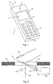
- Figure 1 shows an example of a portable radio communications device, in this case a mobile telephone 1, in which the invention can be used.
- the telephone has an antenna 2, a loudspeaker 3, a microphone 4 and a number of keys 5.
- the keys 5 are used for entering telephone numbers, messages, etc.
- a display 6 is provided for presentation of information to the user of the telephone. This information could be numbers or messages entered by means of the keys 5, or it could be information received by the device through the antenna 2. An example of such information could be a menu from which the user can select a specific item, which is done by moving a cursor or pointer 7 around on the display 6.
- the movement of the cursor 7 is controlled by the cursor control device 8 according to the invention.
- This device 8 is an optical control device which will be described in more detail below.
- the optical control device includes a translucent window integrated into the surface of the telephone 1.
- the position of the cursor 7 is controlled by moving e.g. a finger on the window of the device 8.
- the optical control device 8 may be implemented in several different ways, the construction of which is known per se. One implementation is described below and illustrated in figure 2.
- Figure 2 shows the front cover 11 of the mobile telephone 1 and a translucent window 12 arranged in the front cover.
- the window 12 can be made of any translucent material such as glass or a plastics material, and it is mounted in the front cover in such a way that water, moisture or dust is prevented from entering into the device.
- the area of the window 12 corresponds to the outline of the control device 8 as shown in figure 1.
- a light source 13 is placed behind the window 12.
- the light source 13 will typically be a light emitting diode (LED) or a laser diode, but also other types of light sources are possible.
- a detector 14 sensitive to the light emitted from the light source 13 is also located behind the window 12, and a shield 15 prevents the light from the light source 13 from being transmitted directly to the detector 14.
- the light source 13 may be of a directional type so that no light is emitted in the direction of the detector 14.
- the light source 13 emits light in a relatively narrow wavelength band only, and the detector 14 has a good sensitivity for light in this wavelength band while the sensitivity for light outside this band is lower. This means that in a situation where no objects are located in front of the window 12 the detector 14 will not detect any light from the light source 13, and it will not be disturbed by ambient light outside the band through the window 12. If, however, an object, such as a finger 16 of a user, is placed in front of the window 12, the light from the light source 13 will be reflected and diffused by the finger, as shown in the figure, and some of the reflected and diffused light will have a direction towards the detector 14. A lens 17 focuses this light such that an image of the contact area between the finger 16 and the window 12 is created on the detector 14.
- the detector 14 can be divided into four segments 21, 22, 23 and 24, as shown in figure 3, which shows the situation before the finger 16 is placed on the window 12, i.e. when no light from the light source 13 is received by the detector 14.
- Each of these segments of the detector 14 is adapted to provide an electrical output signal proportional to, or at least dependent on, the amount of light received by the segment. These signals are received by a control circuit 18.
- Figure 4 shows the detector 14 when a finger 16 is placed on the window 12 and an image 25 of the contact area between the finger and the window surface is created on the detector 14 by the light reflected from the finger.
- the image 25 is located mainly in the lower part of the detector so that the two segments 23 and 24 receive more light than the segments 21 and 22. Consequently, the segments 23 and 24 also produce higher output signals than the segments 21 and 22. This could be a situation where the finger 16 is placed on the right side of the window 12 in figure 2.
- the image 25 in figure 4 would move to the right, and the amount of light received by the segments 22 and 23 would decrease while that received by the segments 21 and 24 would increase correspondingly. This would also be the case for the corresponding output signals, and the control signal generated by the control circuit 18 would move the cursor 7 to the right on the display 6.
- this item can be selected by using a separate selection button.
- This button can be a normal mechanical button, or it can be a separate window of the same type like the window 12 where the movement of a finger activates the item indicated by the cursor 7.
- the selection can also be done by movement of the finger on the window 12 itself. As an example, this can be done by placing the finger on the window and then removing it again after a short time, or the finger can simply be removed from the window very fast after the cursor has been moved to the desired location.
- the control circuit 18 can be arranged to be active only when the telephone itself is in an active mode.
- a separate button can be used to switch the cursor control device 8 on and off, so that the user can activate the device when it is needed and then deactivate it again after the use.
- the light source 13 can be of an infrared type, which ensures that the emitted light is not visible from the outside of the window 12. This embodiment is normally preferred, because users are interested in a function and not in how such a function is implemented. On the other hand, an embodiment using light in the visible band will provide the communications device with a high-tech look that could be attractive to especially young people.
- the window 12 has a size which is larger than the contact area between the finger 16 and the window.
- the detector 14 does not need the complete image of the contact area in order to detect the movement thereof. In this case, a detector having more than four segments can be advantageous. As an example, a detector of the type which is normally used as sensors in TV cameras can be used.
- a detector using coherent detection of the light reflected from the finger and utilizing reference light transmitted directly from the light source to detect the movement of the finger can be used.
Landscapes
- Engineering & Computer Science (AREA)
- General Engineering & Computer Science (AREA)
- Theoretical Computer Science (AREA)
- Human Computer Interaction (AREA)
- Physics & Mathematics (AREA)
- General Physics & Mathematics (AREA)
- Telephone Set Structure (AREA)
Priority Applications (5)
| Application Number | Priority Date | Filing Date | Title |
|---|---|---|---|
| EP00610106A EP1204070A1 (fr) | 2000-10-27 | 2000-10-27 | Appareil de radiocommunication portable |
| CNA018180469A CN1471688A (zh) | 2000-10-27 | 2001-10-19 | 便携式无线通信设备 |
| AU2002221723A AU2002221723A1 (en) | 2000-10-27 | 2001-10-19 | A portable radio communications device |
| PCT/EP2001/012195 WO2002035459A1 (fr) | 2000-10-27 | 2001-10-19 | Dispositif de communication radio portatif |
| US09/983,862 US20020052209A1 (en) | 2000-10-27 | 2001-10-26 | Portable radio communications device |
Applications Claiming Priority (1)
| Application Number | Priority Date | Filing Date | Title |
|---|---|---|---|
| EP00610106A EP1204070A1 (fr) | 2000-10-27 | 2000-10-27 | Appareil de radiocommunication portable |
Publications (1)
| Publication Number | Publication Date |
|---|---|
| EP1204070A1 true EP1204070A1 (fr) | 2002-05-08 |
Family
ID=8174417
Family Applications (1)
| Application Number | Title | Priority Date | Filing Date |
|---|---|---|---|
| EP00610106A Withdrawn EP1204070A1 (fr) | 2000-10-27 | 2000-10-27 | Appareil de radiocommunication portable |
Country Status (1)
| Country | Link |
|---|---|
| EP (1) | EP1204070A1 (fr) |
Cited By (3)
| Publication number | Priority date | Publication date | Assignee | Title |
|---|---|---|---|---|
| US7435940B2 (en) | 2003-03-12 | 2008-10-14 | Flatfrog Laboratories Ab | System and a method of determining the position of a radiation emitting element |
| US7442914B2 (en) | 2003-09-12 | 2008-10-28 | Flatfrog Laboratories Ab | System and method of determining a position of a radiation emitting element |
| US7465914B2 (en) | 2003-09-12 | 2008-12-16 | Flatfrog Laboratories Ab | System and method of determining a position of a radiation scattering/reflecting element |
Citations (4)
| Publication number | Priority date | Publication date | Assignee | Title |
|---|---|---|---|---|
| US5424756A (en) * | 1993-05-14 | 1995-06-13 | Ho; Yung-Lung | Track pad cursor positioning device and method |
| US5801681A (en) * | 1996-06-24 | 1998-09-01 | Sayag; Michel | Method and apparatus for generating a control signal |
| US6047197A (en) * | 1996-12-27 | 2000-04-04 | Ericsson Inc. | Icon driven phone menu system |
| US6131047A (en) * | 1997-12-30 | 2000-10-10 | Ericsson Inc. | Radiotelephones having contact-sensitive user interfaces and methods of operating same |
-
2000
- 2000-10-27 EP EP00610106A patent/EP1204070A1/fr not_active Withdrawn
Patent Citations (4)
| Publication number | Priority date | Publication date | Assignee | Title |
|---|---|---|---|---|
| US5424756A (en) * | 1993-05-14 | 1995-06-13 | Ho; Yung-Lung | Track pad cursor positioning device and method |
| US5801681A (en) * | 1996-06-24 | 1998-09-01 | Sayag; Michel | Method and apparatus for generating a control signal |
| US6047197A (en) * | 1996-12-27 | 2000-04-04 | Ericsson Inc. | Icon driven phone menu system |
| US6131047A (en) * | 1997-12-30 | 2000-10-10 | Ericsson Inc. | Radiotelephones having contact-sensitive user interfaces and methods of operating same |
Cited By (3)
| Publication number | Priority date | Publication date | Assignee | Title |
|---|---|---|---|---|
| US7435940B2 (en) | 2003-03-12 | 2008-10-14 | Flatfrog Laboratories Ab | System and a method of determining the position of a radiation emitting element |
| US7442914B2 (en) | 2003-09-12 | 2008-10-28 | Flatfrog Laboratories Ab | System and method of determining a position of a radiation emitting element |
| US7465914B2 (en) | 2003-09-12 | 2008-12-16 | Flatfrog Laboratories Ab | System and method of determining a position of a radiation scattering/reflecting element |
Similar Documents
| Publication | Publication Date | Title |
|---|---|---|
| US20020052209A1 (en) | Portable radio communications device | |
| US12008188B2 (en) | Interactive devices | |
| US6809723B2 (en) | Pushbutton optical screen pointing device | |
| KR100918157B1 (ko) | 휴대용 전자 장치의 메뉴 항목 선택 제어 방법과 사용자식별 방법 및 휴대용 전자 장치 | |
| US7176905B2 (en) | Electronic device having an image-based data input system | |
| US8106885B2 (en) | Input mechanism for handheld electronic communication device | |
| US20110221676A1 (en) | Optical mouse with touch sensitive top | |
| US20090027335A1 (en) | Free-Space Pointing and Handwriting | |
| US6762751B2 (en) | Optical pointing device | |
| US20110169773A1 (en) | Touch keyboard | |
| US20020080117A1 (en) | Optical mouse | |
| JP2000057873A (ja) | 照明付タッチスイッチ | |
| CA2646142C (fr) | Mecanisme d'entree pour dispositif de communication electronique portatif | |
| EP1204070A1 (fr) | Appareil de radiocommunication portable | |
| US20050264542A1 (en) | Stylus with function key | |
| US9317170B2 (en) | Interactive devices | |
| US9435910B2 (en) | Light sensing device for detecting gestures having a casing with a lens receiving aperture disposed immediately adjacent to a display screen | |
| US8269723B2 (en) | Computer mouse with virtual keys | |
| JP2001291458A (ja) | 光学式タッチスイッチ装置 | |
| EP2026169A1 (fr) | Supports de détection | |
| US20100060583A1 (en) | Input devices operable by reflected light | |
| KR100690298B1 (ko) | 착용할 수 있는 초소형 정보 입력 장치 | |
| US20130127711A1 (en) | Touch tracking optical input device | |
| KR100495686B1 (ko) | 광마우스 | |
| KR20080043412A (ko) | 광 포인팅 장치를 구비한 휴대단말기의 키클릭 방법 |
Legal Events
| Date | Code | Title | Description |
|---|---|---|---|
| PUAI | Public reference made under article 153(3) epc to a published international application that has entered the european phase |
Free format text: ORIGINAL CODE: 0009012 |
|
| AK | Designated contracting states |
Kind code of ref document: A1 Designated state(s): AT BE CH CY DE DK ES FI FR GB GR IE IT LI LU MC NL PT SE |
|
| AX | Request for extension of the european patent |
Free format text: AL;LT;LV;MK;RO;SI |
|
| 17P | Request for examination filed |
Effective date: 20021014 |
|
| AKX | Designation fees paid |
Designated state(s): AT BE CH CY DE DK ES FI FR GB GR IE IT LI LU MC NL PT SE |
|
| RAP1 | Party data changed (applicant data changed or rights of an application transferred) |
Owner name: TELEFONAKTIEBOLAGET LM ERICSSON (PUBL) |
|
| 17Q | First examination report despatched |
Effective date: 20071113 |
|
| STAA | Information on the status of an ep patent application or granted ep patent |
Free format text: STATUS: THE APPLICATION IS DEEMED TO BE WITHDRAWN |
|
| 18D | Application deemed to be withdrawn |
Effective date: 20080326 |