EP1204073A2 - Méthode et appareil de génération d'images - Google Patents
Méthode et appareil de génération d'images Download PDFInfo
- Publication number
- EP1204073A2 EP1204073A2 EP01308441A EP01308441A EP1204073A2 EP 1204073 A2 EP1204073 A2 EP 1204073A2 EP 01308441 A EP01308441 A EP 01308441A EP 01308441 A EP01308441 A EP 01308441A EP 1204073 A2 EP1204073 A2 EP 1204073A2
- Authority
- EP
- European Patent Office
- Prior art keywords
- image data
- data
- image
- images
- frequency component
- Prior art date
- Legal status (The legal status is an assumption and is not a legal conclusion. Google has not performed a legal analysis and makes no representation as to the accuracy of the status listed.)
- Granted
Links
Images






Classifications
-
- G—PHYSICS
- G06—COMPUTING OR CALCULATING; COUNTING
- G06T—IMAGE DATA PROCESSING OR GENERATION, IN GENERAL
- G06T15/00—Three-dimensional [3D] image rendering
- G06T15/10—Geometric effects
- G06T15/20—Perspective computation
- G06T15/205—Image-based rendering
-
- G—PHYSICS
- G06—COMPUTING OR CALCULATING; COUNTING
- G06T—IMAGE DATA PROCESSING OR GENERATION, IN GENERAL
- G06T15/00—Three-dimensional [3D] image rendering
- G06T15/04—Texture mapping
Definitions
- the present application concerns method and apparatus for the generation of images.
- the present application concerns method and apparatus for the generation of images of an object from a selected viewpoint from a plurality of images of the same object from other viewpoints.
- a method of generating spacial frequency data for a specified view of an object from a plurality of images of said object comprising the steps of:
- spacial frequency data By generating spacial frequency data directly from the available images of an object, a means is provided to ensure a consistent and efficient method of generating high and low frequency data for a selected image, which does not require a blurring operation for the surface of an object to be determined.
- an apparatus for generating spacial frequency data for a specified view of an object from a plurality of images of said object comprising:
- an embodiment of the invention comprises a processing apparatus 2, such as a personal computer, containing, in a conventional manner, one or more processors, memories, graphics cards etc., together with a display device 4, such as a conventional personal computer monitor, user input devices 6, such as a keyboard, mouse etc. and a printer 8.
- a processing apparatus 2 such as a personal computer, containing, in a conventional manner, one or more processors, memories, graphics cards etc., together with a display device 4, such as a conventional personal computer monitor, user input devices 6, such as a keyboard, mouse etc. and a printer 8.
- the processing apparatus 2 is programmed to operate in accordance with programming instructions input, for example, as data stored on a data storage medium, such as disk 12, and/or as a signal 14 input to the processing apparatus 2, for example from a remote database, by transmission over a communication network (not shown) such as the Internet or by transmission through the atmosphere, and/or entered by a user via a user input device 6 such as a keyboard.
- a communication network not shown
- a user input device 6 such as a keyboard
- the programming instructions comprise instructions to cause the processing apparatus 2 to become configured to process input data defining a plurality of images of a subject object recorded from different view points.
- the input data then is processed to generate data identifying the positions and orientations at which the input images were recorded. These calculated positions and orientations and the image data are then used to generate data defining a three-dimensional computer model of the subject object.
- processing apparatus 2 When programmed by the programming instructions, processing apparatus 2 effectively becomes configured into a number of functional units for performing processing operations. Examples of such functional units and their interconnections are shown in Figure 1. The units and interconnections illustrated in Figure 1 are, however, notional and are shown for illustration purposes only to assist understanding; they do not necessarily represent the exact units and connections into which the processor, memory etc. of the processing apparatus 2 become configured.
- a central controller 20 processes inputs from the user input devices 6, and also provides control and processing for the other functional units.
- Memory 24 is provided for use by central controller 20 and the other functional units.
- Data store 26 stores input data input to the processing apparatus 2 for example as data stored on a storage device, such as disk 28, as a signal 30 transmitted to the processing apparatus 2, or using a user input device 6.
- the input data defines a plurality of colour images of one or more objects recorded at different positions and orientations.
- the input data also includes data defining the intrinsic parameters of the camera which recorded the images, that is, the aspect ratio, focal length, principal point (the point at which the optical axis intersects the imaging plane), first order radial distortion coefficient, and skew angle (the angle between the axes on the pixel grid; because the axes may not be exactly orthogonal).
- the input data defining the input images may be generated for example by downloading pixel data from a digital camera which recorded the images, or by scanning photographs using a scanner (not shown).
- the input data defining the intrinsic camera parameters may be input by a user using a user input device 6.
- Position determination module 32 processes the input images received by the input data store 26 to determine the relative positions and orientations of camera view points from which image data of an object represented by the image data have been obtained. In this embodiment, this is achieved in a conventional manner by identifying and matching features present in the input images and calculating relative positions of camera views utilising these matches.
- Surface modeller 34 processes the data defining the input images and the data defining the positions and orientations at which the images were recorded to generate data defining a 3D computer wire mesh model representing the actual surface(s) of the object(s) in the images.
- this 3D model defines a plurality of triangles representing the surface of the subject object modelled.
- Surface texturer 36 generates texture data from the input image data for rendering onto the surface model produced by surface modeller 34.
- the surface texturer 36 processes the input image data to generate six texture maps comprising six views of a subject object as viewed from a box bounding the subject object. These generated texture maps are then utilized to texture render the surface model so that images of a modelled subject object from any viewpoint may be generated.
- the processing of the surface texturer 36 to generate these texture maps from the input image data will be described in detail later.
- Display processor 40 under the control of central controller 20, displays instructions to a user via display device 4. In addition, under the control of central controller 20, display processor 40 also displays images of the 3D computer model of the object from a user-selected viewpoint by processing the surface model data generated by surface modeller 34 and rendering texture data produced by surface texturer 36 onto the surface model.
- Printer controller 42 under the control of central controller 30 causes hard copies of images of the 3D computer model of the object selected and displayed on the display device 4 to be printed by the printer 8.
- Output data store 44 stores the surface model and texture data therefor generated by surface modeller 34 and surface texturer 36.
- Central controller 20 controls the output of data from output data store 44, for example as data on a storage device, such as disk 46, or as a signal 48.
- this texture data comprises six texture maps, the six texture maps comprising views of subject object from the six faces of a cuboid centred on the subject object.
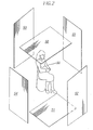
- Figure 2 is an exemplary illustration of the position and orientation of six texture maps 50-55 bounding an exemplary subject object 56.
- the six texture maps comprise texture maps for six canonical views of an object being views of the object from the top 50, bottom 51, front 52, back 53, left 54 and right 55.
- the six canonical views 50-55 comprise three pairs 50,51;52,53;54,55 of parallel image planes, centred on the origin of the coordinate system of the model, with each of the three pairs of image planes aligned along one of the three coordinate axes of the coordinate system respectively.
- the relative positions of the viewpoints of the canonical views 50-55 are then selected so that relative to the size of the model 56 of the subject object created by the surface modeller 34, the distance away from the object is selected so that the canonical views are equally spaced from the centre of the object and the extent of an object as viewed from each image plane is no more than an threshold number of pixels in extent. In this embodiment this threshold is set to be 512 pixels.
- Each of the texture maps for the model is then defined by a weak perspective projection of the subject object 56 onto the defined image planes.
- image data of the model 56 of the subject object from any viewpoint can then be generated using conventional texture rendering techniques, where texture rendering data for each portion of the surface of the model 56 is generated utilizing selected portions of the canonical views 50-56.
- each of the canonical views corresponds to a view of the projection of a real world object the canonical views 50-55 should be representative of realistic views of the subject object and hence be suited for compression by standard image compression algorithms such as JPEG which are optimised for compressing real world images.
- generated images of a model of a subject object may obtain texture rendering data from any of the six canonical texture maps, it is necessary to generate all of the texture maps in such a way that they are all consistent with one another. Thus in this way where different portions of an image of a subject object are rendered utilizing texture maps from different views no noticeable boundaries arise.
- any 3D object not all of the surface of a subject object from all six canonical views 50-55 will be visible in any single input image, it is necessary for the surface texture 36 to combine image data from the plurality of images available to generate texture maps for these six consistent views 50-55.
- FIG. 3 is a schematic block diagram of the surface texturer 36 in accordance with this embodiment of the present invention.
- the surface texturer 36 comprises a weight determination module 58 and a texture map determination module 59.
- the surface texture 36 utilizes position data generated by the position determination module 32 identifying the viewpoints in which data has been obtained and 3D model data output by the surface model. This position data and 3D model data is processed by the weight determination module 58 which initially determines the extent to which portions of the surface of the subject object being modelled are visible in each of the available images. The weight determination module 58 then utilizes this determination to generate weight function data identifying a relative preference for utilizing the available input images for generating texture data for each portion of the surface of the model of the subject object.
- This weight function data is then passed to the texture map determination module 59 which processes the weight function data together with the position data generated by the position determination module 32, the model data generated by the surface modeller 34 and the available image data stored within the input data store 26 to generate a set of six consistent texture maps for the canonical views 50-55.
- weight determination module 58 generating weight function data indicative of relative preferences for utilizing different input images for generating texture data for different portions of a model of a subject object will now be described in detail with reference to Figures 4-9, 10A and 10B.
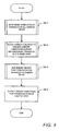
- Figure 4 is a flow diagram of the processing of the weight determination module 58.
- the weight determination module 58 determines (S4-1) data indicative of the extent to which each of the triangles of the 3D model generated by the surface modeller 34 is visible in each of the images in the input store 26.
- each triangle is visible in the available images. In this way it is possible to select as preferred sources of image data for generating portions of texture maps, images where particular triangles are clearly visible, for example in a close up images, rather than images where a triangle whilst visible is viewed only at an acute angle, or from a great distance.
- Figure 5 is a flow diagram illustrating in detail of the processing of the weight determination module 58 to determine the visibility of triangles in input images, utilizing the 3D model data generated by the surface modeller 34 and the position data for the input images determined by the position determination module 32.
- the weight determination module 58 selects the first view for which position data has been generated by the position determination module 32.
- the weight determination module 58 selects (S5-2) the first triangle of the 3D model generated by the surface modeller 34.
- the weight determination module 58 determines a visibility value for the triangle being processed as seen from the perspective defined by the position data being processed.
- this is achieved by utilizing conventional Open GL calls to render the 3D model generated by the surface modeller 34 as seen from the perspective defined by the position data of the image being processed.
- the generated image data is then utilized to calculate the visibility value.
- a visibility value for the triangle being processed as viewed from the viewpoint defined by the currently selected position data is then determined by calculating the number of pixels in the image rendered in the second and third colours.
- a visibility value of one is associated with the triangle and position data.
- a visibility value of one is associated with the triangle at image position.
- the fraction of pixels rendered in the third colour relative to the total is less than the threshold value a visibility value of zero is assigned to the triangle as viewed from the position defined by the position data.
- the processing of the weight determination module 58 to colour a triangle by rendering and a triangle utilizing the stored values in the Z buffer as previously described enables triangles to be processed even if two small adjacent triangles are mapped to the same pixel in the selected viewpoint. Specifically, if triangle depths are similar for triangles corresponding to the same portion of an image, the glPolygonOffset call has the effect of rendering the second colour in the front of other triangles the same distance from the selected viewpoint. Thus when the visibility of the selected triangle is determined, the triangle is only given a lower visibility value if it is obscured by other triangles closer to the defined viewpoint and not merely obscured by the rendering of triangles at the same distance to the same portion of an image.
- the weight determination module 58 calculates and stores a visibility score for the triangle in the selected viewpoint utilizing this visibility value.
- a value indicative of the extent to which a triangle in a model is or is not occluded from the selected viewpoint is determined.
- Other factors also effect the extent to which use of particular portion image data for generating texture data may be preferred. For example, close up images are liable to contain more information about the texture of an object and therefore may be preferable sources for generating texture data.
- a further factor which may determine whether a particular image is preferable to use for generating texture data is the extent to which a portion of the image is viewed at oblique angle.
- the weight determination module 58 determines whether the triangle for which data has just been stored is the last of the triangles identified by the model data generated by the surface modeller 34. If this is not the case the weight determination module 58 then proceeds to select (S5-6) the next triangle of the model data generated by the surface modeller 34 and then determines a visibility value (S5-3) and calculates and stores a visibility score (S5-4) for that next triangle.
- the weight determination module 58 determines that the triangle for which a visibility score has been stored is the last triangle of the 3D model data generated by the surface modeller 34.
- the weight determination module 58 selects (S5-8) the next set of position data to generate and store visibility scores for each of the triangles as perceived from that new position (S5-2-S5-7).
- the weight determination module 58 generates and stores visibility scores for all triangles as perceived from each of the viewpoints corresponding to viewpoints of input image data in the input data store 26.
- the weight determination module 58 proceeds to alter the visibility scores for the triangles perceived in each view to ensure smooth variation in the scores across neighbouring triangles.
- the visibility scores are utilized to generate weight functions indicative of a relative preference for using portions of different input images stored within the input data store 26 for generating texture rendering data.
- weight function data which generates a continuous and reasonably smooth weight function so that image data from different sources is blended into one another.
- the triangles forming the 3D model data can be of significantly different sizes, a first stage in generating such a smooth weighting function is to average weighting values across areas of the model to account for this variation in triangle size.
- Figure 6 is a flow diagram of the detailed processing of the weight determination module 58 to alter the visibility score associated with triangles as perceived from a particular viewpoint.
- the weight determination module 58 repeats processing illustrated by Figure 6 for each of the sets of visibility score data associated with triangles corresponding to each of the views for which image data is stored within the input store 26 so that visibility score data associated with adjacent triangles as perceived from each viewpoint identified by position data determined by the position determination module 32 varies relatively smoothly across the surface of the model.
- the weight determination module 58 selects the first triangle identified by 3D model data output from the surface modeller 34.
- the weight determination module 58 determines whether the stored visibility score of the visibility of that triangle as perceived from the view being processed is set to zero. If this is the case no modification of the visibility score is made (S6-3). This ensures that the visibility scores associated with triangles which have been determined to be completely occluded or substantially occluded from the viewpoint being processed remain associated with a visibility score of zero, and hence are not subsequently used to generate texture map data.
- the weight determination module 58 determines (S6-2) that the visibility score of the triangle being processed is not equal to zero the weight determination module 58 then (S6-4) determines the surface area of the triangle from the 3D vertices using standard methods. The weight determination module then (S6-5) determines whether the total surface area exceeds the threshold value.
- the threshold value is set to be equal to the square of 5% of the length of the bounding box defined by the six canonical views 50-55.
- the weight determination module 58 determines that the total surface area does not exceed this threshold the weight determination module then (S6-6) selects the triangles adjacent to the triangle under consideration, being those triangles having 3D model data sharing two vertices with the triangle under consideration. The weight determination module 58 then calculates (S6-4,S6-5) the total surface for the selected triangle and those adjacent to the selected triangle to determine once again whether the number of pixels the projection of this area onto the image plane corresponding to the viewpoint against which triangles are being processed exceeds the threshold value. This process is repeated until the total surface area corresponding to the selected triangles exceeds the threshold.
- the weight determination module 58 sets as an initial revised visibility score for the central triangle, where the initial revised score is equal to the average visibility score associated with all the currently selected triangles weighted by surface.
- a threshold value typically set to 10% of the maximum unmodified weight is then subtracted from this revised initial visibility score. Any negative values associated with triangles are then set to zero. This threshold causes triangles associated with low weights to be associated with a zero visibility score. Errors in calculating camera position and hence visibility scores might result in low weights being assigned to triangles where surfaces are not in fact visible. The reduction of visibility scores in this way ensures that any such errors do not introduce subsequent errors in generated texture map data. The final revised visibility score for the triangle is then stored.
- Figures 7 and 8 are an exemplary illustration of the processing of an area of a model in order to revise the visibility scores to ensure a smooth variation in scores regardless of the size of the triangles.
- Figure 7 is an exemplary illustration of an area of a model comprising nine triangles, each triangle associated with a visibility score corresponding to the number appearing within respective triangles.
- the area of the triangle is determined. If this area is determined to be below the threshold value, the adjacent triangles, the shaded triangles in Figure 7, are selected and the area corresponding to the crossed hatched triangle and the shaded triangles is then determined.
- Figure 8 is an exemplary illustration of the area of a model corresponding to the same area illustrated in Figure 7 after all of the visibility scores for the triangles have been processed and modified where necessary. As can be seen by comparing the values associated with triangles in Figure 7 and Figure 8, wherever a triangle is associated with a zero in Figure 7 it remains associated with a zero in Figure 8. However the variation across the remaining triangle is more gradual than the variation illustrated in Figure 7, as these new scores correspond to area weighted averages of the visibility scores in Figure 7.
- the weight determination module 58 determines (S6-8) whether all of the visibility scores for the triangles in a model, as seen from a viewpoint have been processed. If this is not the case the weight determination module 58 then (S6-9) selects the next triangle for processing.
- the weight determination module 58 calculates weight function data for all of the triangles in all of the views so that a smooth weight function indicative of the visibility of the surface of the model as seen from each defined viewpoint can be generated.
- weight determination module 58 for generating weight function data for a model for a single view will now be described in detail with reference to Figures 9, 10A and 10B. This processing is then repeated for the other views so that weight function data for all of the views is generated.
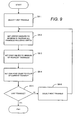
- Figure 9 is a flow diagram of the processing of the weight determination module 58 to generate weight function data for the surface of a model defined by 3D model data received from the surface modeller 34 for a view as defined by one set of position data output by the position determination module 32 for which visibility scores have been determined and modified.
- the weight determination module 58 selects (S9-1) the first triangle of the model.
- the weight determination module 58 determines for each of the vertices of the selected triangle the minimum visibility score associated with triangles in the model sharing that vertex. These minimum visibility scores are then stored as weight function data for the points of the model corresponding to those vertices.
- the weight determination module 58 determines for each of the edges of the selected triangle the lesser visibility score of the currently selected triangle and the adjacent triangle which shares that common edge. These values are then stored as weight function data defining the weight to be associated with the mid point of each of the identified edges.
- the weight determination module 58 then (S9-4) stores as weight function data the visibility score associated with the currently selected triangle as the weight function to be associated with the centroid of the selected triangle.
- weight function data By allotting weight function data for the vertices, edges and centroids of each of the triangles for the models generated by the surface modeller 34, values for the entirety of the surface of the model of an object can then be determined by interpolating the remaining points of the surface of the model as will be described later.
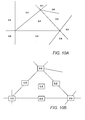
- Figures 10A is an illustrative example of a selection of triangles each associated with a visibility score.
- Figure 10B is an example of the weight functions associated with the vertices, edges and centroid of the triangle in Figure 10A associated with a visibility score of 0.5.
- the selection of weight function data for the vertices and edges of a triangle to be such that the weight function is the minimum of scores associated with triangles having a common edge or vertex ensures that the weight function associated with the edge or vertex of triangles adjacent to a triangle with a visibility score of zero are all set to zero.
- the weight determination module 58 determines (S9-5) whether the triangle currently under consideration is the last of the triangles in the model generated by the surface modeller 34.
- next triangle is then selected (S9-6) and weight function data is determined and stored for the newly selected triangle (S9-2-S9-4).
- weight function data for generating a weight function that varies smoothly across the surface of a modelled object and reduces to zero for all portions of a model which are not visible from a viewpoint associated with the weight function is generated.
- this weight function data is then (S4-4) output by the weight determination module 58 to the texture map determination module 59 so that the texture map determination module 59 can utilize the calculated weight function data to select portions of image data to be utilized to generate texture maps for a generated model.
- the weight function data generated output by the weight determination module 58 are calculated so as to be representative of a relative visibility of portions of the surface of a model from defined viewpoints.
- the projected images of the weight functions are therefore indicative of relative preferences for using the corresponding portions of projections of image data from the corresponding viewpoints to generating the texture data for the texture map for each of the canonical views.
- These projected weight function images hereinafter referred to as canonical confidence images can therefore be utilized to select portions of projected image data to blend to generate output texture maps for canonical views 50-55.
- Figure 11 is a schematic diagram of notional functional modules of the texture map determination module 59 for generating canonical texture maps for each of the canonical views 50-55 from image data stored within the input data store 26, position data output by the position determination module 32, 3D model data generated by the surface modeller 34 and the weight function data output by the weight determination module 58.
- the texture generation module 59 comprises a low frequency image generation module 60 for extracting low frequency image information from image data stored within the input data store 26, an image projection module 62 for generating high and low frequency canonical image projections; a confidence image generation module 64 for generating canonical confidence images; a weighted average filter 66 and a blending module 68 for processing high and low frequency canonical projections and the canonical confidence images to generate blended high and low frequency canonical images; and a re-combination of output module 70 for combining the high and low frequency images and outputting the combined images as texture maps for each of the canonical views 50-55.
- each item of image data in the input data store 26 is passed to the low frequency image generation module 60.
- This module 60 then generates a set of low frequency images by processing the image data for each of the views in a conventional way by blurring and sub-sampling each image.
- the blurring operation is achieved by performing a Gausian blur operation in which the blur radius is selected to be the size of the projection of a cube placed at the centre of the object bounding box defined by the six canonical views 50-55 and whose sides are 5% of the length of the diagonal of the bounding box.
- the selection of the blur radius in this way ensures that the radius is independent of image resolution and varies depending upon whether the image is a close up of a subject object (large radius) or the subject appears small in the image (small radius).
- These low frequency images are then passed to the image projection module 62 together with copies of the original image data stored within the input data store 26, position data for each of the images as determined by the position determination module 32 and 3D model data for the model generated by the surface modeller 34.
- the image projection module For each of the input images from the input data store 26 the image projection module then utilizes the position data associated with the image and the 3D model data output by the surface modeller 34 to determine calculated projections of the input images as perceived from the six canonical views 50-55 by utilizing standard texture rendering techniques.
- the image projection module 62 generates for each of low frequency images corresponding to image data processed by the low frequency image generation module 60, six low frequency canonical projections for the six canonical views 50-55.
- Six high frequency canonical image projections for each image are then determined by the image projection module 62 by performing a difference operation, subtracting the low frequency canonical image projections for an image as viewed from a specified canonical view from the corresponding image projection of the raw image data for that view.
- the low frequency canonical projections and high frequency canonical projections of each image for each of the six canonical views are then passed to the weighted average filter 66 and the blending module 68 for processing as will be detailed later.
- the confidence image generation module 64 is arranged to receive 3D model data from the surface modeller 34 and weight function data from the weight function determination module 58. The confidence image generation module 64 then processes the 3D model data and weight function data to generate for each of the weight functions associated with viewpoints corresponding to the viewpoints of each input images in the input data store 26, a set of six canonical confidence images for the six canonical views 50-55.
- each triangle for which weight function data has been stored is first processed by linking the midpoint of each edge of the triangle to the midpoints of the two other edges and linking each of the midpoints of each edge and the centroid of the triangle.
- Each of these defined small triangles is then projected into the six canonical views with values for points corresponding to each part of the projection of each small triangle being interpolated using a standard OpenGL "smooth shading" interpolation from the weight function data associated with the vertices of these small triangles.
- a canonical confidence image for each weight function is generated.
- the pixel values of canonical confidence images generated in this way are each representative of the relative preference for utilizing corresponding portions of canonical projections of image data representative of the viewpoint for which the weight function was generated to generate texture map data.
- These canonical confidence images are then passed to the weighted average filter 66 and the blending module 68, so that texture data for the six canonical views can be generated utilizing the data identifying preferred sources for generating portions of texture map data.
- the weighted average filter 66 and blending module 68 receive, for each item of image data stored within the input data store 26 a set of six canonical confidence images identifying the extent to which portions of projected images derived from a specified image are to be preferred to generate texture data and a set of six projections of either the high or low frequency images corresponding to the item of image data.
- the weighted average filter 66 and the blending module 68 then proceed to process the confidence images and associated low and high frequency canonical projections in turn for each of the canonical views as will now be described in detail.
- Figure 12 is a flow diagram of the processing of low frequency canonical projections and associated canonical confidence images for a specified canonical view for each of a set of input images stored within the input data store 26.
- the weighted average filter 66 selects a first low frequency canonical projection and its associated confidence image. This is then made the basis of an initial low frequency canonical image to be generated by the weighted average filter 66. The weighted average filter 66 then selects (S12-2) the next low frequency projection for the same canonical view together with the projection's associated confidence image.
- the weighted average filter 66 determines as a new low frequency canonical image a canonical image comprising for each pixel in the image a weighted average of the current low frequency canonical image and the selected low frequency canonical projection weighted by the confidence scores utilising the following formula: where C is the current confidence score associated with the pixel being processed for the canonical image and C i is the confidence score associated with the pixel in the confidence image associated with the selected projection.
- the weighted average filter 66 determines whether the latest selected low frequency canonical projection is the last of the low frequency canonical projections for the canonical view currently being calculated. If this is not the case the weighted average filter 66 then proceeds to utilize the determined combined image to generate a new combined image utilizing the next confidence image and associated low frequency image projection (S12-2-S12-4).
- the weighted average filter 66 determines (S12-4) that the last of the low frequency canonical projections for a specified canonical view 50-55 has been processed the weighted average filter 66 outputs (S12-5) as a blended canonical low frequency image the image generated utilizing the weighted average of the last projected image processed by the average weighted filter 66.
- the weighted average filter 66 enables for each of the canonical views 50-55 a low frequency image to be created combining each of the low frequency canonical projections weighted by confidence scores indicative of the portions of the images identified as being most representative of the surface texture of a model in the canonical confidence images.
- the low frequency images are representative of average local colour of surfaces as effected by global lighting effects
- this processing by the weighted average filter 66 enables canonical low frequency images to be generated in which these global lighting effects are averaged across the best available images where greater weight is placed on images in which portions of a model are most easily viewed giving the resultant canonical low frequency images a realistic appearance and a neutral tone.
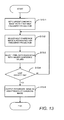
- Figure 13 is a flow diagram of the processing of canonical confidence images and associated high frequency canonical projections for generating a canonical high frequency image for one of the canonical views 50-55. This processing is repeated for each of the canonical views 50-55.
- the processing of the blending module 68 for generating high frequency canonical images is identical to that of the processing of the weighted average filter 66 except instead of determining weighted averages of pixels in the canonical projections and canonical images, in this embodiment the blending module 68 selects as canonical image data pixel data, pixel data associated with the greatest confidence scores.
- the blending module 68 then updates the pixels in the current high frequency canonical image (S13-3).
- the blending module 68 selecting for each pixel in the image either pixel data for the corresponding pixel in the high frequency canonical projection being processed or the pixel data for the current high frequency canonical image. The selection is made for each pixel by determining whether the corresponding pixel in the confidence image associated with the high frequency projection being processed has a greater confidence score than the confidence score associated with the pixel in the current canonical image. The pixel data associated with the highest score is then utilised as pixel data for the canonical image. The confidence score associated with the pixel in the updated canonical image is then set to the greater of the confidence scores for the pixel as identified by either the confidence image associated with the canonical image or the projection currently be processed.
- the blending module 68 determines (S13-4) whether all of the high frequency image projections for a canonical user have been processed. If this is not the case then the next projection and confidence image are utilised to update the high frequency canonical image being generated (S13-2-S13-4). When all of the canonical projections have been processed the final canonical image is then output (S13-5).
- a high frequency canonical image is generated utilising all of the available high frequency image projections where each pixel of the high frequency canonical image corresponds to pixel data from the available high frequency image projections associated with the greatest of the confidence scores for that pixel
- the high frequency canonical images therefore correspond to a patchwork of the best available pixel data for each part of the high frequency canonical images
- the recombination and output module 70 When the six canonical low frequency images and six canonical high frequency images are then received by the recombination output module 70 for each canonical view 50-55 the recombination and output module 70 generates a single canonical texture map by adding the high and low frequency images for each view. The combined canonical texture maps are then output by the recombination and output module 70 for storage in the output data store 44 together with the 3D model data generated by the surface module 34.
- the output canonical texture maps can then be utilized to texture render image representations of the model generated by the surface modeller 34 by associating each of the triangles identified by the three-dimensional model data with one of the texture maps.
- the selection of texture data to texture render each triangle is determined by selecting as the map to be utilized the map in which the triangle has the greatest visibility score in which the visibility score is calculated for each canonical view 50-55 in the same way as has previously been described in relation to Figure 5. Texture co-ordinates for texture rendering the model generated by the surface modeller 34 are then implicitly defined by the projection of the triangle onto the selected canonical view 50-55.
- Images of the model of the subject object can then be obtained for any viewpoint utilizing the output canonical texture maps and the 3D model data stored in the output data store 44, for display on the display device 4 and a hard copies of the generated images can be made utilizing the printer.
- the model data and texture map stored in the output data store 44 can also be output as data onto a storage device 46,48.
- an image processing apparatus in which input data defining a plurality of images of a subject object recorded from different viewpoints were processed to generate texture data comprising six canonical texture maps being views for a cuboid bounding a model of the subject object.
- texture data comprising six canonical texture maps being views for a cuboid bounding a model of the subject object.
- an image processing apparatus in which texture data is generated to ensure that all triangles within a 3D model are rendered utilizing texture data for the corresponding portion of the surface of a subject object, if image data representative of the corresponding portion of the subject object is available.
- the image processing apparatus in accordance with this embodiment of the present invention is identical to that of the previous embodiment except the surface texturer 36 is replaced with a modified surface texturer 80.
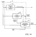
- Figure 14 is a schematic block diagram of the notional functional modules of the modified surface texturer module 80.
- the modified surface texturer 80 comprises a canonical view determination module 82; a weight determination module 58 identical to the weight determination module 58 of the surface texturer 36 of the previous embodiment and a modified texture map determination module 86.
- the canonical view determination module 82 is arranged to determine from the 3D model data output by the surface modeller 34 whether any portions of the surface of the 3D model are not visible from the six initial canonical views. If this is determined to be the case the canonical view determination module 82 proceeds to define further sets of canonical views for storing texture data for these triangles. These view definitions are then passed to the texture map determination module 86. The modified texture map determination module 86 then generates canonical texture map data for the initial canonical views and these additional canonical views which are then utilized to texture render the surface of the model generated by the surface modeller 34.
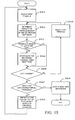
- the canonical view determination module 82 selects a first triangle of the model generated by the surface modeller 34.
- the canonical view determination module 82 then (S15-2) generates a visibility value and visibility score for the triangle as perceived from each of the six canonical views in a similar manner to which the visibility value is generated by a weight determination module 58 as has previously been described in relation to the previous embodiment.
- the canonical view determination module 82 determines whether the visibility value associated with the triangle being processed is greater than a threshold value indicating that the triangle is at least substantially visible in at least one of the views.
- this threshold value is set to zero so that all triangles which are at least 75% visible in one of the views are identified as being substantially visible.
- the canonical view determination module 82 determines that the triangle being processed is visible i.e. has a visibility value of greater than zero in at least one view, the canonical view determination module selects from the available canonical views the view in which the greatest visibility score as generated in the manner previously described is associated with the triangle. Data identifying the canonical view in which the selected triangle is most visible is then stored. Thus in this way data identifying the canonical view in which texture data for rendering the triangle is subsequently to be utilized is generated.
- the canonical view determination module 82 determines whether the currently selected triangle corresponds to the last triangle of the 3D model generated by the surface modeller 34. If this is not the case the canonical view determination module 82 then proceeds to select the next triangle and determine visibility values and visibility scores for that next triangle (S15-6-S15-5).
- the canonical view determination module 82 determines whether data identifying a best view has been stored for all of the triangles.
- the canonical view determination module 82 If this is not the case the canonical view determination module 82 generates and stores a list of triangles for which no best view data has been stored (S15-8) the canonical view determination module 82 then proceeds to establish the visibility of these remaining triangles in the six canonical views in the absence of the triangles for which best view data has already been stored (15-1-S15-7). This process is then repeated until best view data is stored for all of the triangles.
- the canonical view determination module 82 determines (S15-7) that best view data has been stored for all the triangles the canonical view determination module 82 then outputs (S15-9) view definition data comprising for each triangle the canonical view in which it is most visible together with the generated lists of the triangles not visible canonical views. These lists and identified views in which the triangles are best represented are then output and passed to the modified texture map determination module 86.
- the modified texture map determination module 86 processes the 3D model data, weight function data, image data and position data this generates the six original canonical views in the same manner as has been described in relation to the first embodiment.
- the texture map determination module 86 generates for the triangles not visible in the original six canonical views as identified by the lists output by the canonical view determination module 82 further texture maps corresponding to the projection of the triangles identified by the lists of triangles generated by the canonical view determination module 82 in the six canonical views in the absence of the other triangles.
- These additional canonical views are generated from the high and low frequency canonical projections of image data generated by the image projection module 62 of the modified texture map determination module 86 and additional canonical confidence images being canonical projections of only the triangles identified by the lists of triangles output by the canonical view determination module 82.
- These additional confidence images being calculated for the triangles identified in the lists utilizing the weight function data generated by the weight determination module 58 in the same way as has previously been described in relation to the first embodiment.
- the original canonical views together with these additional canonical views can then be utilized to texture render the model where the texture maps utilized to render each triangle is selected utilizing the lists and the data identifying the best views as are output by the canonical view determination module 82.
- a blending module 68 which selected pixel data corresponding to the pixels associated with the highest confidence scores for the corresponding pixel in associated confidence images.
- a problem with such a selection system is that boundaries can develop in the generated texture map data indicative of the selection of pixel data from different image sources.
- the obvious solution to this problem performing an average operation such as that performed by the weighted average filter 66 is undesirable as this results in loss of contrast within the texture maps data.
- the blending module 68 is arranged to process high frequency canonical projections in a way which avoids noticeable boundaries arising within texture map data, whilst maintaining image contrast.
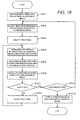
- Figure 17 is a flow diagram of the processing canonical confidence images and associated high frequency canonical image projections by the blending module 68 in accordance with this embodiment of the present invention.
- the blending module 68 selects a first one of the high frequency canonical projections for the canonical view for which a canonical high frequency image is to be generated and sets as an initial canonical high frequency image an image corresponding to the selected first high frequency projection.
- the blending module 68 selects the next high frequency canonical projection for that canonical view and its associated canonical confidence image for processing.
- the first pixel within the canonical high frequency image is then selected (S16-3) and the blending module 68 then (S16-4) determines for the selected pixel in the high frequency canonical image a difference value between the pixel in the current high frequency canonical image and in the corresponding pixel in the high frequency canonical projection being processed.
- this difference value may be calculated by determining the sum of the differences between corresponding values for each of the red, green and blue channels for the corresponding pixels in the selected high frequency canonical projection and the canonical high frequency image being generated.
- this difference value could be determined by calculating the difference between the pixel in the canonical high frequency image and the corresponding pixel in the high frequency canonical projection being processed.
- any suitable function of the red, green and blue channel values for corresponding pixels in the high frequency canonical projection being processed and the canonical high frequency image being generated could be utilized to generate a difference value for a pixel.
- the blending module 68 determines a blend function for the selected pixel from the confidence scores associated with the pixel and the determined difference value for the pixel.
- this blend function is initially determined by selecting a gradient G in dependence upon the determined difference value for the pixel.
- the difference values D are calculated from colour image data for three colour channels each varying from 0 to 255, the value of D 0 is set to be 60.
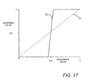
- Figure 14 is a graph of a generated blend function illustrating the manner in which the final weighting value W calculated in this way varies in dependence upon the relative confidence score C i /(C + C i ) for a pixel being processed and the determined difference value D for the pixel.
- solid line 72 indicates a graph for calculating W for weighting values where D is equal to a high value, for example in this embodiment where D ranges between 0 and 765 a value of over 700.
- the graph indicates that where the relative confidence score for a particular source is low a weighting value of zero is selected and for high pixel confidence scores, a weighting factor of one is selected. For intermediate pixel confidence scores an intermediate weighting factor is determined, the weighting factor increasing as the confidence score increases.
- the dotted line 74 in Figure 17 is an illustration of the blend function where the calculated value D for the difference between the image data of the first and second images for a pixel is less than or equal to the blend constant D 0 .
- the blend function comprises a function which sets a weighting value equal to the pixel relative confidence score for the pixel.
- the blend function varies between the solid line 72 and the dotted line 74 with the thresholds below which or above which a weighting value of zero or one is output reducing and increasing as D decreases.
- D decreases the proportion of relative confidence scores for which a weighting value other than zero or one is output increases.
- the blending module 68 then proceeds to calculate and store blended pixel data (S16-6) for the pixel under consideration.
- the calculated blended pixel data is determined for each of the three colour channels by:
- the confidence value associated with the blended pixel is then also updated by selecting and storing as a new confidence score for the pixel the greater of the current confidence score associated with the pixel in the canonical image and the confidence score of the pixel in the projection being processed.
- the effect of calculating the pixel data for pixels in the high frequency canonical image in this way is to make the pixel data dependent upon both the difference data and the confidence data associated with the processed pixel in the selected high frequency canonical projection.
- the difference data for a pixel is low (i.e. less than or equal to the blend constant D 0 ) calculated pixel data corresponding to a weighted average proportional to the relative confidence score for the pixel in the associated canonical image is utilized.
- difference data is higher (i.e. greater than the blend constant D 0 ) a pair of threshold values are set based upon the actual value of the difference data.
- Pixel data is then generated in two different ways depending upon the relative confidence score for the pixel in the associated canonical image.
- the relative confidence score is above or below these threshold values either only the original pixel data for the canonical image or the pixel data for the selected high frequency canonical projection is utilized as a composite image data. If the relative confidence score is between the threshold values a weighted average of the original pixel data and pixel data from the selected projection is utilized.
- the blending module 68 determines (S16-7) whether the pixel currently under consideration is the last of the pixels in the canonical image. If this not the case the non-linear averaging filter then (S16-8) selects the next pixel and repeats the determination of a difference value (S16-4) a blend function (S16-5) and the calculation and storage of pixel data (S16-6) for the next pixel.
- the blending module 68 determines (S16-7) that blended pixel data has been stored for all of the pixels of the high frequency canonical image, the blending module 68 then determines (S16-9) whether the selected high frequency canonical projection and associated confidence image is the last high frequency canonical projection and confidence image to be processed. If this is not the case the next high frequency canonical projection is selected (S16-2) and the canonical high frequency image is updated utilizing this newly selected projection (S16-3-S16), and its associated confidence image.
- the blending module 68 determines that the latest high frequency canonical projection utilized to update a canonical high frequency image is the last of the high frequency canonical projections, the blending module 68 then (S16-10) outputs as a high frequency image for the canonical view 50-55 the high frequency canonical image updated by the final high frequency projection.
- an averaging operation does not degrade apparent image quality. Performing an averaging across such areas of composite image, therefore provides a means by which the relative weight attached to different sources of image data can be varied so that the boundaries between areas of a composite image obtained from different source images can be made less distinct.
- weighting factors are selected on the basis of both confidence data and difference data for a pixel so that, relative to weighting factors proportional to confidence data only as occurs in the weighted average filter 66, in the blending module 68, where determined differences between the source images are higher, the weighting given to preferred source data is increased and the corresponding weighting given to less preferred data is decreased.
- weighting values proportional to confidence data are not modified at all or only slightly so that the boundaries between portions of image data generated from different images are minimised across those areas.
- composite image data can be obtained which maintains the level of contrast and detail in original high frequency source data, whilst minimising apparent boundaries between portions of composite image generated from different items of source data.
- a set of images of a subject object is described as being utilized to generate 3D model data and texture render data for generating representations of that subject object.
- texture render data obtained utilizing images of one object could for example be utilized to generate representations of a second object.
- the mixing of a model obtained for one object and texture derived from a second object could be utilized to establish how the application of texture from different objects varies the appearance of a model.
- confidence images of a first object from any number of views can be generated in a similar manner as has previously been described.
- Source images of a different object can then be processed using the confidence images as if the source images had been generated.
- the processing of the source images in this way would then generate texture data in which the texture in the source images was blended smoothly across the surface of the first object.
- a number of confidence images could be generated for views of a model.
- the confidence images of the model viewed from viewpoints to one side of the model might be associated with an image of a first texture for example a wood grain.
- the remaining confidence images of the model might be associated with a second texture e.g. marble. Processing these two source images with the generated confidence images would generate texture data in which one side of the model appeared having a wood grain texture and the other a marble texture with the two textures being smoothly blended across the surface of the model.
- images of a different object as viewed from viewpoints for which confidence images were generated could be used.
- images of a model first object could be generated as has previously been described for a number of viewpoints.
- Confidence images for a second object could be generated for those corresponding viewpoints and texture data for the second object obtained by processing the images of the first object utilizing the confidence images of the second object.
- the embodiments of the invention described with reference to the drawings comprise computer apparatus and processes performed in computer apparatus, the invention also extends to computer programs, particularly computer programs on or in a carrier, adapted for putting the invention into practice.
- the program may be in the form of source or object code or in any other form suitable for use in the implementation of the processes according to the invention.
- the carrier be any entity or device capable of carrying the program.
- the carrier may comprise a storage medium, such as a ROM, for example a CD ROM or a semiconductor ROM, or a magnetic recording medium, for example a floppy disc or hard disk.
- a storage medium such as a ROM, for example a CD ROM or a semiconductor ROM, or a magnetic recording medium, for example a floppy disc or hard disk.
- the carrier may be a transmissible carrier such as an electrical or optical signal which may be conveyed via electrical or optical cable or by radio or other means.
- the carrier When a program is embodied in a signal which may be conveyed directly by a cable or other device or means, the carrier may be constituted by such cable or other device or means.
- the carrier may be an integrated circuit in which the program is embedded, the integrated circuit being adapted for performing, or for use in the performance of, the relevant processes.
Landscapes
- Engineering & Computer Science (AREA)
- Theoretical Computer Science (AREA)
- Physics & Mathematics (AREA)
- Computer Graphics (AREA)
- General Physics & Mathematics (AREA)
- Computing Systems (AREA)
- Geometry (AREA)
- Image Generation (AREA)
- Processing Or Creating Images (AREA)
- Image Analysis (AREA)
Applications Claiming Priority (4)
| Application Number | Priority Date | Filing Date | Title |
|---|---|---|---|
| GB0026343 | 2000-10-27 | ||
| GB0026343A GB0026343D0 (en) | 2000-10-27 | 2000-10-27 | Image generation method and apparatus |
| GB0112204 | 2001-05-18 | ||
| GB0112204A GB0112204D0 (en) | 2000-10-27 | 2001-05-18 | Image generation method and apparatus |
Publications (3)
| Publication Number | Publication Date |
|---|---|
| EP1204073A2 true EP1204073A2 (fr) | 2002-05-08 |
| EP1204073A3 EP1204073A3 (fr) | 2005-01-19 |
| EP1204073B1 EP1204073B1 (fr) | 2007-01-31 |
Family
ID=26245204
Family Applications (1)
| Application Number | Title | Priority Date | Filing Date |
|---|---|---|---|
| EP01308441A Expired - Lifetime EP1204073B1 (fr) | 2000-10-27 | 2001-10-03 | Méthode et appareil de génération d'images |
Country Status (4)
| Country | Link |
|---|---|
| US (2) | US7120289B2 (fr) |
| EP (1) | EP1204073B1 (fr) |
| JP (1) | JP3782709B2 (fr) |
| DE (1) | DE60126387D1 (fr) |
Cited By (7)
| Publication number | Priority date | Publication date | Assignee | Title |
|---|---|---|---|---|
| GB2407953A (en) * | 2003-11-07 | 2005-05-11 | Canon Europa Nv | Texture data editing for three-dimensional computer graphics |
| US7019754B2 (en) | 2002-10-29 | 2006-03-28 | Canon Europa N.V. | Apparatus and method for generating texture maps for use in 3D computer graphics |
| US7280106B2 (en) | 2002-10-21 | 2007-10-09 | Canon Europa N.V. | Apparatus and method for generating texture maps for use in 3D computer graphics |
| US7304647B2 (en) | 2003-04-02 | 2007-12-04 | Canon Europa N.V. | Generating texture maps for use in 3D computer graphics |
| US7463269B2 (en) | 2004-06-14 | 2008-12-09 | Canon Europa N.V. | Texture data compression and rendering in 3D computer graphics |
| US7528831B2 (en) | 2003-09-18 | 2009-05-05 | Canon Europa N.V. | Generation of texture maps for use in 3D computer graphics |
| WO2019156971A1 (fr) * | 2018-02-06 | 2019-08-15 | A9.Com, Inc. | Texturation tridimensionnelle photoréaliste à l'aide de vues canoniques et d'une approche en deux étapes |
Families Citing this family (83)
| Publication number | Priority date | Publication date | Assignee | Title |
|---|---|---|---|---|
| US8489176B1 (en) | 2000-08-21 | 2013-07-16 | Spectrum Dynamics Llc | Radioactive emission detector equipped with a position tracking system and utilization thereof with medical systems and in medical procedures |
| WO2004042546A1 (fr) * | 2002-11-04 | 2004-05-21 | V-Target Technologies Ltd. | Dispositif et procedes de formation d'images et de correction d'attenuation |
| US8565860B2 (en) | 2000-08-21 | 2013-10-22 | Biosensors International Group, Ltd. | Radioactive emission detector equipped with a position tracking system |
| US8036731B2 (en) | 2001-01-22 | 2011-10-11 | Spectrum Dynamics Llc | Ingestible pill for diagnosing a gastrointestinal tract |
| US8909325B2 (en) | 2000-08-21 | 2014-12-09 | Biosensors International Group, Ltd. | Radioactive emission detector equipped with a position tracking system and utilization thereof with medical systems and in medical procedures |
| DE60126387D1 (de) * | 2000-10-27 | 2007-03-22 | Canon Kk | Bilderzeugungsverfahren und Bilderzeugungsgerät |
| IL157007A0 (en) | 2001-01-22 | 2004-02-08 | Target Technologies Ltd V | Ingestible device |
| GB2383245B (en) | 2001-11-05 | 2005-05-18 | Canon Europa Nv | Image processing apparatus |
| GB0126526D0 (en) * | 2001-11-05 | 2002-01-02 | Canon Europa Nv | Three-dimensional computer modelling |
| EP1347418A3 (fr) | 2002-02-28 | 2005-11-23 | Canon Europa N.V. | Edition de mapage de texture |
| GB0208909D0 (en) | 2002-04-18 | 2002-05-29 | Canon Europa Nv | Three-dimensional computer modelling |
| US20040116807A1 (en) * | 2002-10-17 | 2004-06-17 | Roni Amrami | Blood vessels wall imaging catheter |
| US7069108B2 (en) | 2002-12-10 | 2006-06-27 | Jostens, Inc. | Automated engraving of a customized jewelry item |
| GB2398469B (en) * | 2003-02-12 | 2005-10-26 | Canon Europa Nv | Image processing apparatus |
| JP2004252603A (ja) * | 2003-02-18 | 2004-09-09 | Canon Inc | 三次元データ処理方法 |
| GB2405775B (en) * | 2003-09-05 | 2008-04-02 | Canon Europa Nv | 3D computer surface model generation |
| JP2005100040A (ja) * | 2003-09-24 | 2005-04-14 | Fuji Photo Film Co Ltd | テクスチャの生成システムおよびその生成方法 |
| US20050091016A1 (en) * | 2003-09-29 | 2005-04-28 | Autodesk, Inc. | Surface smoothing techniques |
| US7561990B2 (en) * | 2003-09-29 | 2009-07-14 | Autodesk, Inc. | Interactive triangulated irregular network (TIN) surfaces design |
| US7523396B2 (en) * | 2003-09-29 | 2009-04-21 | Autodesk, Inc. | Surface construction audit trail and manipulation |
| US8571881B2 (en) | 2004-11-09 | 2013-10-29 | Spectrum Dynamics, Llc | Radiopharmaceutical dispensing, administration, and imaging |
| US9470801B2 (en) | 2004-01-13 | 2016-10-18 | Spectrum Dynamics Llc | Gating with anatomically varying durations |
| US9040016B2 (en) | 2004-01-13 | 2015-05-26 | Biosensors International Group, Ltd. | Diagnostic kit and methods for radioimaging myocardial perfusion |
| WO2007054935A2 (fr) * | 2005-11-09 | 2007-05-18 | Spectrum Dynamics Llc | Camera dynamique pour gammatomographie |
| CN1981210A (zh) | 2004-01-13 | 2007-06-13 | 光谱动力学有限责任公司 | 多维图像重构 |
| US7968851B2 (en) | 2004-01-13 | 2011-06-28 | Spectrum Dynamics Llc | Dynamic spect camera |
| US8586932B2 (en) | 2004-11-09 | 2013-11-19 | Spectrum Dynamics Llc | System and method for radioactive emission measurement |
| US10964075B2 (en) | 2004-01-13 | 2021-03-30 | Spectrum Dynamics Llc | Gating with anatomically varying durations |
| WO2005101326A1 (fr) * | 2004-04-19 | 2005-10-27 | Jostens, Inc. | Systeme et procede de lissage d'images tridimensionnelles |
| US8280124B2 (en) | 2004-06-01 | 2012-10-02 | Spectrum Dynamics Llc | Methods of view selection for radioactive emission measurements |
| EP1778957A4 (fr) | 2004-06-01 | 2015-12-23 | Biosensors Int Group Ltd | Optimisation de la mesure d'emissions radioactives dans des structures corporelles specifiques |
| US9316743B2 (en) | 2004-11-09 | 2016-04-19 | Biosensors International Group, Ltd. | System and method for radioactive emission measurement |
| US8423125B2 (en) | 2004-11-09 | 2013-04-16 | Spectrum Dynamics Llc | Radioimaging |
| US8606349B2 (en) | 2004-11-09 | 2013-12-10 | Biosensors International Group, Ltd. | Radioimaging using low dose isotope |
| US8615405B2 (en) | 2004-11-09 | 2013-12-24 | Biosensors International Group, Ltd. | Imaging system customization using data from radiopharmaceutical-associated data carrier |
| US10136865B2 (en) | 2004-11-09 | 2018-11-27 | Spectrum Dynamics Medical Limited | Radioimaging using low dose isotope |
| WO2008059489A2 (fr) | 2006-11-13 | 2008-05-22 | Spectrum Dynamics Llc | Application à la radioimagerie de nouvelles formules de téboroxime |
| US7872235B2 (en) | 2005-01-13 | 2011-01-18 | Spectrum Dynamics Llc | Multi-dimensional image reconstruction and analysis for expert-system diagnosis |
| US7711162B2 (en) * | 2005-01-27 | 2010-05-04 | Siemens Medical Solutions Usa, Inc. | Accelerated texture-based fusion renderer |
| US8837793B2 (en) | 2005-07-19 | 2014-09-16 | Biosensors International Group, Ltd. | Reconstruction stabilizer and active vision |
| US8644910B2 (en) | 2005-07-19 | 2014-02-04 | Biosensors International Group, Ltd. | Imaging protocols |
| US7680314B2 (en) * | 2005-10-17 | 2010-03-16 | Siemens Medical Solutions Usa, Inc. | Devices, systems, and methods for improving image consistency |
| US8204500B2 (en) | 2005-12-28 | 2012-06-19 | Starhome Gmbh | Optimal voicemail deposit for roaming cellular telephony |
| US7751592B1 (en) * | 2006-01-13 | 2010-07-06 | Google Inc. | Scoring items |
| WO2007109704A2 (fr) * | 2006-03-22 | 2007-09-27 | Cornell Research Foundation, Inc. | Système d'indice de visibilité en imagerie médicale et méthode relative aux lésions cancéreuses |
| US8894974B2 (en) | 2006-05-11 | 2014-11-25 | Spectrum Dynamics Llc | Radiopharmaceuticals for diagnosis and therapy |
| WO2008075362A2 (fr) | 2006-12-20 | 2008-06-26 | Spectrum Dynamics Llc | Procédé, système et appareil pour utiliser et traiter des données multidimensionnelles |
| EP2109800A1 (fr) | 2007-01-18 | 2009-10-21 | Jostens, Inc. | Système et procédé destinés à générer des instructions pour la personnalisation |
| MX2009009622A (es) | 2007-03-12 | 2009-12-01 | Jostens Inc | Metodo para colocacion de adornos. |
| US8471853B2 (en) * | 2007-10-26 | 2013-06-25 | Via Technologies, Inc. | Reconstructable geometry shadow mapping method |
| US8521253B2 (en) | 2007-10-29 | 2013-08-27 | Spectrum Dynamics Llc | Prostate imaging |
| US8700477B2 (en) * | 2009-05-26 | 2014-04-15 | Embodee Corp. | Garment fit portrayal system and method |
| US8364561B2 (en) * | 2009-05-26 | 2013-01-29 | Embodee Corp. | Garment digitization system and method |
| US8338788B2 (en) | 2009-07-29 | 2012-12-25 | Spectrum Dynamics Llc | Method and system of optimized volumetric imaging |
| US8977377B2 (en) * | 2010-02-25 | 2015-03-10 | Jostens, Inc. | Method for digital manufacturing of jewelry items |
| KR101232729B1 (ko) * | 2011-01-28 | 2013-02-13 | 한국과학기술연구원 | 자세 교정 방법 및 시스템 |
| US9196086B2 (en) * | 2011-04-26 | 2015-11-24 | Here Global B.V. | Method, system, and computer-readable data storage device for creating and displaying three-dimensional features on an electronic map display |
| US9208265B2 (en) | 2011-12-02 | 2015-12-08 | Jostens, Inc. | System and method for jewelry design |
| US9582615B2 (en) | 2013-01-16 | 2017-02-28 | Jostens, Inc. | Modeling using thin plate spline technology |
| USD789228S1 (en) | 2013-11-25 | 2017-06-13 | Jostens, Inc. | Bezel for a ring |
| CN104836977B (zh) * | 2014-02-10 | 2018-04-24 | 阿里巴巴集团控股有限公司 | 即时通讯过程中的视频通讯方法及系统 |
| US10423858B2 (en) | 2014-07-21 | 2019-09-24 | Ent. Services Development Corporation Lp | Radial histogram matching |
| US20170124726A1 (en) * | 2015-11-02 | 2017-05-04 | Canon Kabushiki Kaisha | System and method for determining wall thickness |
| EP3419286A1 (fr) * | 2017-06-23 | 2018-12-26 | Koninklijke Philips N.V. | Traitement d'information d'images 3d sur la base de cartes de texture et reseaux |
| JP2019040229A (ja) * | 2017-08-22 | 2019-03-14 | キヤノン株式会社 | 画像処理装置、画像処理方法及びプログラム |
| US11348303B2 (en) * | 2017-08-31 | 2022-05-31 | Sony Group Corporation | Methods, devices, and computer program products for 3D texturing |
| US10861196B2 (en) | 2017-09-14 | 2020-12-08 | Apple Inc. | Point cloud compression |
| US10909725B2 (en) | 2017-09-18 | 2021-02-02 | Apple Inc. | Point cloud compression |
| WO2019142179A1 (fr) | 2018-01-21 | 2019-07-25 | Anzu Virtual Reality Ltd | Système et procédé de détermination de visibilité d'objets |
| US10867414B2 (en) | 2018-04-10 | 2020-12-15 | Apple Inc. | Point cloud attribute transfer algorithm |
| US10762702B1 (en) * | 2018-06-22 | 2020-09-01 | A9.Com, Inc. | Rendering three-dimensional models on mobile devices |
| US11012713B2 (en) | 2018-07-12 | 2021-05-18 | Apple Inc. | Bit stream structure for compressed point cloud data |
| US20210241430A1 (en) * | 2018-09-13 | 2021-08-05 | Sony Corporation | Methods, devices, and computer program products for improved 3d mesh texturing |
| US11430155B2 (en) | 2018-10-05 | 2022-08-30 | Apple Inc. | Quantized depths for projection point cloud compression |
| US11665372B2 (en) * | 2019-01-07 | 2023-05-30 | Samsung Electronics Co., Ltd. | Fast projection method in video-based point cloud compression codecs |
| CN109961418A (zh) * | 2019-03-19 | 2019-07-02 | 中国林业科学研究院资源信息研究所 | 一种基于多时相光学遥感数据的无云影像合成算法 |
| US11711544B2 (en) | 2019-07-02 | 2023-07-25 | Apple Inc. | Point cloud compression with supplemental information messages |
| US12488529B1 (en) * | 2021-02-18 | 2025-12-02 | Cisco Technology, Inc. | Mesh retexturing in an extended reality environment |
| US11915377B1 (en) | 2021-02-18 | 2024-02-27 | Splunk Inc. | Collaboration spaces in networked remote collaboration sessions |
| US12112435B1 (en) | 2021-02-18 | 2024-10-08 | Splunk Inc. | Collaboration spaces in extended reality conference sessions |
| US11893675B1 (en) | 2021-02-18 | 2024-02-06 | Splunk Inc. | Processing updated sensor data for remote collaboration |
| US12106419B1 (en) * | 2021-02-18 | 2024-10-01 | Splunk Inc. | Live updates in a networked remote collaboration session |
| US11948338B1 (en) * | 2021-03-29 | 2024-04-02 | Apple Inc. | 3D volumetric content encoding using 2D videos and simplified 3D meshes |
Family Cites Families (32)
| Publication number | Priority date | Publication date | Assignee | Title |
|---|---|---|---|---|
| US2003A (en) * | 1841-03-12 | Improvement in horizontal windivhlls | ||
| JPH02121481A (ja) | 1988-10-28 | 1990-05-09 | Nippon Telegr & Teleph Corp <Ntt> | 画像蓄積方式 |
| US5414803A (en) * | 1991-01-11 | 1995-05-09 | Hewlett-Packard Company | Method utilizing frequency domain representations for generating two-dimensional views of three-dimensional objects |
| JPH06259571A (ja) | 1993-03-04 | 1994-09-16 | Matsushita Electric Ind Co Ltd | 画像合成装置 |
| JP2883514B2 (ja) | 1993-06-10 | 1999-04-19 | 株式会社ナムコ | 画像合成装置およびこれを用いたゲーム装置 |
| JPH07230555A (ja) | 1993-12-22 | 1995-08-29 | Matsushita Electric Ind Co Ltd | ミップマップ画像生成装置および生成方法 |
| JP3704734B2 (ja) | 1994-01-26 | 2005-10-12 | 株式会社日立製作所 | テクスチャマッピング方法及び装置 |
| JPH08147494A (ja) | 1994-11-17 | 1996-06-07 | Matsushita Electric Ind Co Ltd | 頭髪画像生成装置 |
| US5649078A (en) * | 1995-03-22 | 1997-07-15 | International Business Machines Corporation | Efficient two-pass rasterization scheme utilizing visibility information |
| US5872572A (en) | 1995-12-08 | 1999-02-16 | International Business Machines Corporation | Method and apparatus for generating non-uniform resolution image data |
| US6084979A (en) | 1996-06-20 | 2000-07-04 | Carnegie Mellon University | Method for creating virtual reality |
| JP3625624B2 (ja) | 1996-08-30 | 2005-03-02 | 三洋電機株式会社 | テクスチャ情報付与方法、テクスチャ情報付与プログラムを記録した媒体およびテクスチャ情報付与装置 |
| US6137893A (en) | 1996-10-07 | 2000-10-24 | Cognex Corporation | Machine vision calibration targets and methods of determining their location and orientation in an image |
| US6160557A (en) * | 1996-10-17 | 2000-12-12 | International Business Machines Corporation | Method and apparatus providing efficient rasterization with data dependent adaptations |
| US6204859B1 (en) | 1997-10-15 | 2001-03-20 | Digital Equipment Corporation | Method and apparatus for compositing colors of images with memory constraints for storing pixel data |
| JPH11328441A (ja) | 1998-05-11 | 1999-11-30 | Hitachi Ltd | グラフィックス表示制御方法およびコンピュータグラフイックス |
| US6157743A (en) * | 1998-07-31 | 2000-12-05 | Hewlett Packard Company | Method for retrieving compressed texture data from a memory system |
| US6178392B1 (en) | 1998-09-22 | 2001-01-23 | Intel Corporation | Method for combining the computer models of two surfaces in 3-D space |
| US6434265B1 (en) * | 1998-09-25 | 2002-08-13 | Apple Computers, Inc. | Aligning rectilinear images in 3D through projective registration and calibration |
| US6271847B1 (en) * | 1998-09-25 | 2001-08-07 | Microsoft Corporation | Inverse texture mapping using weighted pyramid blending and view-dependent weight maps |
| JP2000137815A (ja) | 1998-11-02 | 2000-05-16 | Gen Tec:Kk | 新視点画像生成方法 |
| JP2000268189A (ja) | 1999-03-18 | 2000-09-29 | Airemu Software Engineering Kk | 画像表示方法、画像表示装置およびそれを備えた遊技機並びにプログラムを記憶した記憶媒体 |
| JP4308367B2 (ja) | 1999-06-02 | 2009-08-05 | 株式会社バンダイナムコゲームス | 3次元画像生成装置および環境マップの生成方法 |
| GB9921777D0 (en) | 1999-09-16 | 1999-11-17 | Koninkl Philips Electronics Nv | Method and apparatus for handling translucency in 3d graphics |
| JP2001126084A (ja) | 1999-10-28 | 2001-05-11 | Sega Corp | テクスチャ表示装置、テクスチャ表示方法及び記録媒体 |
| US7065242B2 (en) * | 2000-03-28 | 2006-06-20 | Viewpoint Corporation | System and method of three-dimensional image capture and modeling |
| US7728848B2 (en) * | 2000-03-28 | 2010-06-01 | DG FastChannel, Inc. | Tools for 3D mesh and texture manipulation |
| GB2362793B (en) | 2000-05-24 | 2004-06-02 | Canon Kk | Image processing apparatus |
| DE60126387D1 (de) * | 2000-10-27 | 2007-03-22 | Canon Kk | Bilderzeugungsverfahren und Bilderzeugungsgerät |
| GB2369541B (en) | 2000-10-27 | 2004-02-11 | Canon Kk | Method and aparatus for generating visibility data |
| GB2377870B (en) | 2001-05-18 | 2005-06-29 | Canon Kk | Method and apparatus for generating confidence data |
| GB2381429B (en) * | 2001-09-28 | 2005-07-27 | Canon Europa Nv | 3D computer model processing apparatus |
-
2001
- 2001-10-03 DE DE60126387T patent/DE60126387D1/de not_active Expired - Lifetime
- 2001-10-03 EP EP01308441A patent/EP1204073B1/fr not_active Expired - Lifetime
- 2001-10-19 US US09/981,844 patent/US7120289B2/en not_active Expired - Fee Related
- 2001-10-29 JP JP2001331574A patent/JP3782709B2/ja not_active Expired - Fee Related
-
2006
- 2006-09-13 US US11/531,626 patent/US7545384B2/en not_active Expired - Fee Related
Non-Patent Citations (3)
| Title |
|---|
| DEBEVEC P E ET AL: "MODELING AND RENDERING ARCHITECTURE FROM PHOTOGRAPHS: A HYBRID GEOMETRY-AND IMAGE-BASED APPROACH" COMPUTER GRAPHICS PROCEEDINGS 1996 (SIGGRAPH). NEW ORLEANS, AUG. 4 - 9, 1996, COMPUTER GRAPHICS PROCEEDINGS (SIGGRAPH), NEW YORK, NY : ACM, US, 4 August 1996 (1996-08-04), pages 11-20, XP000682717 * |
| LENSCH H P A ET AL: "Automated texture registration and stitching for real world models" COMPUTER GRAPHICS AND APPLICATIONS, 2000. PROCEEDINGS. THE EIGHTH PACIFIC CONFERENCE ON HONG KONG, CHINA 3-5 OCT. 2000, LOS ALAMITOS, CA, USA,IEEE COMPUT. SOC, US, 3 October 2000 (2000-10-03), pages 317-452, XP010523024 ISBN: 0-7695-0868-5 * |
| NEUGEBAUER P J ET AL: "TEXTURING 3D MODELS OF REAL WORLD OBJECTS FROM MULTIPLE UNREGISTERED PHOTOGRAPHIC VIEWS" COMPUTER GRAPHICS FORUM, AMSTERDAM, NL, vol. 18, no. 3, 7 September 1999 (1999-09-07), pages C245-C256,C413, XP001034480 ISSN: 0167-7055 * |
Cited By (12)
| Publication number | Priority date | Publication date | Assignee | Title |
|---|---|---|---|---|
| US7280106B2 (en) | 2002-10-21 | 2007-10-09 | Canon Europa N.V. | Apparatus and method for generating texture maps for use in 3D computer graphics |
| US7019754B2 (en) | 2002-10-29 | 2006-03-28 | Canon Europa N.V. | Apparatus and method for generating texture maps for use in 3D computer graphics |
| US7304647B2 (en) | 2003-04-02 | 2007-12-04 | Canon Europa N.V. | Generating texture maps for use in 3D computer graphics |
| US7528831B2 (en) | 2003-09-18 | 2009-05-05 | Canon Europa N.V. | Generation of texture maps for use in 3D computer graphics |
| GB2407953A (en) * | 2003-11-07 | 2005-05-11 | Canon Europa Nv | Texture data editing for three-dimensional computer graphics |
| US7463269B2 (en) | 2004-06-14 | 2008-12-09 | Canon Europa N.V. | Texture data compression and rendering in 3D computer graphics |
| WO2019156971A1 (fr) * | 2018-02-06 | 2019-08-15 | A9.Com, Inc. | Texturation tridimensionnelle photoréaliste à l'aide de vues canoniques et d'une approche en deux étapes |
| US10515477B2 (en) | 2018-02-06 | 2019-12-24 | A9.Com, Inc. | Photorealistic three dimensional texturing using canonical views and a two-stage approach |
| GB2587895A (en) * | 2018-02-06 | 2021-04-14 | A9 Com Inc | Photorealistic three dimensional texturing using canonical views and a two stage approach |
| US11069122B2 (en) | 2018-02-06 | 2021-07-20 | A9.Com, Inc. | Photorealistic three dimensional texturing using canonical views and a two-stage approach |
| GB2587895B (en) * | 2018-02-06 | 2022-03-16 | A9 Com Inc | Photorealistic three dimensional texturing using canonical views and a two-stage approach |
| US11551404B2 (en) | 2018-02-06 | 2023-01-10 | A9.Com, Inc. | Photorealistic three dimensional texturing using canonical views and a two-stage approach |
Also Published As
| Publication number | Publication date |
|---|---|
| US7120289B2 (en) | 2006-10-10 |
| EP1204073A3 (fr) | 2005-01-19 |
| US20070025624A1 (en) | 2007-02-01 |
| US7545384B2 (en) | 2009-06-09 |
| JP3782709B2 (ja) | 2006-06-07 |
| US20020085748A1 (en) | 2002-07-04 |
| JP2002183761A (ja) | 2002-06-28 |
| EP1204073B1 (fr) | 2007-01-31 |
| DE60126387D1 (de) | 2007-03-22 |
Similar Documents
| Publication | Publication Date | Title |
|---|---|---|
| EP1204073B1 (fr) | Méthode et appareil de génération d'images | |
| US7006089B2 (en) | Method and apparatus for generating confidence data | |
| US9020241B2 (en) | Image providing device, image providing method, and image providing program for providing past-experience images | |
| US7463269B2 (en) | Texture data compression and rendering in 3D computer graphics | |
| KR101035103B1 (ko) | 3차원 모델을 스케일링하기 위한 방법 및 스케일링 디바이스 | |
| US7528831B2 (en) | Generation of texture maps for use in 3D computer graphics | |
| US5568595A (en) | Method for generating artificial shadow | |
| WO2004019621A1 (fr) | Procede et dispositif pour creer des images a vision tridimensionnelle | |
| CN110248242B (zh) | 一种图像处理和直播方法、装置、设备和存储介质 | |
| Schirmacher et al. | High-quality interactive lumigraph rendering through warping | |
| EP1355276A2 (fr) | Procédé et dispositif de rendu d'image ajusté de distance | |
| US20070206025A1 (en) | Image Processor and Method, Computer Program, and Recording Medium | |
| TW201828255A (zh) | 用於產生光強度影像之裝置與方法 | |
| KR102807991B1 (ko) | 광 강도 이미지를 생성하기 위한 장치 및 방법 | |
| GB2369260A (en) | Generation of composite images by weighted summation of pixel values of the separate images | |
| GB2369541A (en) | Method and apparatus for generating visibility data | |
| KR100360487B1 (ko) | 2차원 얼굴 영상의 3차원 얼굴 모델로의 텍스쳐 매핑 방법및 그 장치 | |
| CN119784921A (zh) | 模型渲染方法、装置和电子设备 | |
| JP6898264B2 (ja) | 合成装置、方法及びプログラム | |
| US8212835B1 (en) | Systems and methods for smooth transitions to bi-cubic magnification | |
| EP1239416A1 (fr) | Procédé et dispositif de calcul des sources lumineuses dans une scène et permettant de générer des effets photometriques mutuels | |
| GB2406253A (en) | Image rendering in 3D computer graphics using visibility data | |
| GB2407953A (en) | Texture data editing for three-dimensional computer graphics | |
| EP1239417A1 (fr) | Procédé et dispositif de calcul des sources lumineuses dans une scène et permettant de générer des effects photométriques mutuels |
Legal Events
| Date | Code | Title | Description |
|---|---|---|---|
| PUAI | Public reference made under article 153(3) epc to a published international application that has entered the european phase |
Free format text: ORIGINAL CODE: 0009012 |
|
| AK | Designated contracting states |
Kind code of ref document: A2 Designated state(s): AT BE CH CY DE DK ES FI FR GB GR IE IT LI LU MC NL PT SE TR |
|
| AX | Request for extension of the european patent |
Free format text: AL;LT;LV;MK;RO;SI |
|
| PUAL | Search report despatched |
Free format text: ORIGINAL CODE: 0009013 |
|
| AK | Designated contracting states |
Kind code of ref document: A3 Designated state(s): AT BE CH CY DE DK ES FI FR GB GR IE IT LI LU MC NL PT SE TR |
|
| AX | Request for extension of the european patent |
Extension state: AL LT LV MK RO SI |
|
| 17P | Request for examination filed |
Effective date: 20050701 |
|
| AKX | Designation fees paid |
Designated state(s): DE FR GB IT NL |
|
| GRAP | Despatch of communication of intention to grant a patent |
Free format text: ORIGINAL CODE: EPIDOSNIGR1 |
|
| GRAS | Grant fee paid |
Free format text: ORIGINAL CODE: EPIDOSNIGR3 |
|
| GRAA | (expected) grant |
Free format text: ORIGINAL CODE: 0009210 |
|
| AK | Designated contracting states |
Kind code of ref document: B1 Designated state(s): DE FR GB IT NL |
|
| PG25 | Lapsed in a contracting state [announced via postgrant information from national office to epo] |
Ref country code: NL Free format text: LAPSE BECAUSE OF FAILURE TO SUBMIT A TRANSLATION OF THE DESCRIPTION OR TO PAY THE FEE WITHIN THE PRESCRIBED TIME-LIMIT Effective date: 20070131 |
|
| REG | Reference to a national code |
Ref country code: GB Ref legal event code: FG4D |
|
| REF | Corresponds to: |
Ref document number: 60126387 Country of ref document: DE Date of ref document: 20070322 Kind code of ref document: P |
|
| NLV1 | Nl: lapsed or annulled due to failure to fulfill the requirements of art. 29p and 29m of the patents act | ||
| EN | Fr: translation not filed | ||
| PLBE | No opposition filed within time limit |
Free format text: ORIGINAL CODE: 0009261 |
|
| STAA | Information on the status of an ep patent application or granted ep patent |
Free format text: STATUS: NO OPPOSITION FILED WITHIN TIME LIMIT |
|
| 26N | No opposition filed |
Effective date: 20071101 |
|
| PG25 | Lapsed in a contracting state [announced via postgrant information from national office to epo] |
Ref country code: DE Free format text: LAPSE BECAUSE OF FAILURE TO SUBMIT A TRANSLATION OF THE DESCRIPTION OR TO PAY THE FEE WITHIN THE PRESCRIBED TIME-LIMIT Effective date: 20070501 |
|
| PG25 | Lapsed in a contracting state [announced via postgrant information from national office to epo] |
Ref country code: FR Free format text: LAPSE BECAUSE OF FAILURE TO SUBMIT A TRANSLATION OF THE DESCRIPTION OR TO PAY THE FEE WITHIN THE PRESCRIBED TIME-LIMIT Effective date: 20070921 Ref country code: IT Free format text: LAPSE BECAUSE OF FAILURE TO SUBMIT A TRANSLATION OF THE DESCRIPTION OR TO PAY THE FEE WITHIN THE PRESCRIBED TIME-LIMIT Effective date: 20070131 |
|
| PG25 | Lapsed in a contracting state [announced via postgrant information from national office to epo] |
Ref country code: FR Free format text: LAPSE BECAUSE OF FAILURE TO SUBMIT A TRANSLATION OF THE DESCRIPTION OR TO PAY THE FEE WITHIN THE PRESCRIBED TIME-LIMIT Effective date: 20070131 |
|
| PGFP | Annual fee paid to national office [announced via postgrant information from national office to epo] |
Ref country code: GB Payment date: 20121016 Year of fee payment: 12 |
|
| GBPC | Gb: european patent ceased through non-payment of renewal fee |
Effective date: 20131003 |
|
| PG25 | Lapsed in a contracting state [announced via postgrant information from national office to epo] |
Ref country code: GB Free format text: LAPSE BECAUSE OF NON-PAYMENT OF DUE FEES Effective date: 20131003 |