EP1204196A2 - Gelenkantrieb - Google Patents
Gelenkantrieb Download PDFInfo
- Publication number
- EP1204196A2 EP1204196A2 EP01107951A EP01107951A EP1204196A2 EP 1204196 A2 EP1204196 A2 EP 1204196A2 EP 01107951 A EP01107951 A EP 01107951A EP 01107951 A EP01107951 A EP 01107951A EP 1204196 A2 EP1204196 A2 EP 1204196A2
- Authority
- EP
- European Patent Office
- Prior art keywords
- pairs
- movable element
- magnetic poles
- driving apparatus
- stator
- Prior art date
- Legal status (The legal status is an assumption and is not a legal conclusion. Google has not performed a legal analysis and makes no representation as to the accuracy of the status listed.)
- Withdrawn
Links
- 238000001816 cooling Methods 0.000 claims description 7
- 239000000428 dust Substances 0.000 claims description 3
- 238000010586 diagram Methods 0.000 description 7
- 230000004907 flux Effects 0.000 description 2
- 210000003205 muscle Anatomy 0.000 description 2
- 229910000831 Steel Inorganic materials 0.000 description 1
- 230000003247 decreasing effect Effects 0.000 description 1
- 239000002991 molded plastic Substances 0.000 description 1
- 239000010959 steel Substances 0.000 description 1
Images







Classifications
-
- B—PERFORMING OPERATIONS; TRANSPORTING
- B25—HAND TOOLS; PORTABLE POWER-DRIVEN TOOLS; MANIPULATORS
- B25J—MANIPULATORS; CHAMBERS PROVIDED WITH MANIPULATION DEVICES
- B25J17/00—Joints
- B25J17/02—Wrist joints
-
- H—ELECTRICITY
- H02—GENERATION; CONVERSION OR DISTRIBUTION OF ELECTRIC POWER
- H02K—DYNAMO-ELECTRIC MACHINES
- H02K41/00—Propulsion systems in which a rigid body is moved along a path due to dynamo-electric interaction between the body and a magnetic field travelling along the path
- H02K41/02—Linear motors; Sectional motors
- H02K41/03—Synchronous motors; Motors moving step by step; Reluctance motors
- H02K41/031—Synchronous motors; Motors moving step by step; Reluctance motors of the permanent magnet type
Definitions
- the present invention relates to a joint driving apparatus for generating a relative movement between first and second members on a joint.
- a rotational motor is used to generate a relative movement between first and second members on a joint.
- a linear motor is used to generate the relative movement between first and second members on the joint, and a stator structure of the linear motor is similar to that of the rotational motor.
- An object of the present invention is to provide a joint driving apparatus for generating a relative movement between first and second members on a joint, by which apparatus a magnetic flux is effectively utilized to generate a force for urging the first and second members with respect to each other.
- a joint driving apparatus for generating a relative movement between first and second members on a joint, comprising, a linear motor including at least one stator part fixed to another one of the first and second members, a movable element movable with respect to the stator part in a movable direction and connected to the one of the first and second members to be moved with respect to the another one of the first and second members, and an electromagnetic coil device for energizing the stator part to be magnetized so that a magnetic field for urging the movable element in the movable direction with respect to the stator part is generated
- the stator part includes at least two pairs of magnetic poles, the at least two pairs are adjacent to each other in the movable direction, the magnetic poles of each of the at least two pairs face to each other through the movable element in a traverse direction perpendicular to the movable direction to generate the magnetic field passing the magnetic poles through the movable element, and a magnetic polar direction of one of the at least two pairs is opposite
- the joint driving apparatus may further comprise a sensor for generating a signal corresponding to an actual movement of the movable element with respect to the stator part, wherein the electromagnetic coil device controls a change in energized phase of the stator part on the basis of a comparison between the signal and an instructed movement of the movable element with respect to the stator parts to form a closed-loop control system.
- the electromagnetic coil device may control a change in energized phase of the stator part on the basis of an instructed movement of the movable element with respect to the stator part to form an open-loop control system.
- An actual movement of the movable element with respect to the stator part may be estimated from a voltage induced in the electromagnetic coil device by the actual movement of the movable element or from an electric current flowing through the electromagnetic coil device.
- the electromagnetic coil device energizes the at least two stator parts respectively to be magnetized with a difference in energized phase between the at least two stator parts so that a travelling magnetic field for urging the movable element in the movable direction is generated by a cooperation between the at least two stator parts
- P is a pitch of the pairs of the magnetic poles adjacent to each other in the movable direction in each of the stator parts
- k is an integral number not less than zero
- M is a number of the stator parts energized with respective energized phases different from each other while M is an integral number not less than two
- a distance between the pair of magnetic poles of one of the stator parts and the pair of magnetic poles of another one of the stator parts adjacent to each other in the movable direction (k*P) + (P/M) .
- the joint driving apparatus may further comprise an elastic member a part of which is connected to one of the first and second members, wherein the movable element is connected to another part of the elastic member to drive the one of the first and second members through the elastic member with respect to the another one of the first and second members.
- the apparatus may comprise a plurality of pairs of the elastic members and linear motors while the relative movement between the first and second members is performed along each of directions different from each other by respective one of the pairs of the elastic members and linear motors.
- the apparatus may comprise a plurality of the elastic members while the relative movement between the first and second members is performed along each of directions different from each other by respective one of the elastic members connected selectively to the linear motor.
- the joint driving apparatus may further comprise a dust cover covering a portion of the movable element projecting from the stator parts.
- the joint driving apparatus may further comprise a cooling device for cooling the linear motor.
- the joint driving apparatus may further comprise a switching device for switching, between a battery and an outer electric power source, an electric power supply source for supplying an electric power to the linear motor.
- the joint driving may further comprise a spring member for urging the movable element with respect to the another one of the first and second members in the movable direction.
- the elastic member may include a spring for connecting elastically between the movable element and the one of the first and second members.
- the elastic member may include a rubber for connecting elastically between the movable element and the one of the first and second members.
- first one of the magnetic poles of each of the at least two pairs faces to a first side surface of the movable element
- second one of the magnetic poles of each of the at least two pairs faces to a second side surface of the movable element opposite to the first side surface in the traverse direction
- a magnetic polar direction between the first one of the magnetic poles of one of the at least two pairs and the second one of the magnetic poles of the one of the at least two pairs is opposite to a magnetic polar direction between the first one of the magnetic poles of another one of the at least two pairs and the second one of the magnetic poles of the another one of the at least two pairs
- the at least two pairs is magnetized by single electromagnetic coil, a number of electromagnetic coils for the linear motor is minimized.
- the stator part has a magnetic core and the electromagnetic coil device has an electromagnetic coil surrounding an intermediate portion of the magnetic core between longitudinal ends of the magnetic core to generate a magnetic field passing the longitudinal ends of the magnetic core so that the at least two pairs of magnetic poles are energized by the electromagnetic coil, and one of the longitudinal ends of the magnetic core forms both of the first one of the magnetic poles of the one of the at least two pairs and the second one of the magnetic poles of the another one of the at least two pairs while another one of the longitudinal ends of the magnetic core forms both of the first one of the magnetic poles of the another one of the at least two pairs and the second one of the magnetic poles of the one of the at least two pairs, a size of the magnetic core is minimized.
- the apparatus comprises at least two of the stator parts energized respectively to be magnetized with a difference in energized phase between the at least two stator parts so that a travelling magnetic field for urging the movable element in the movable direction is generated by a cooperation between the at least two stator parts, and each of the stator parts is magnetized by single electromagnetic coil, a number of electromagnetic coils for the linear motor is minimized.
- the apparatus comprises at least two of the stator parts energized respectively to be magnetized with a difference in energized phase between the at least two stator parts so that a travelling magnetic field for urging the movable element in the movable direction is generated by a cooperation between the at least two stator parts, and the at least two pairs of magnetic poles in one of the stator parts is energized by single electromagnetic coil and the at least two pairs of magnetic poles in another one of the stator parts is energized by another single electromagnetic coil, a number of electromagnetic coils for the linear motor is minimized.
- the stator part is magnetized by single electromagnetic coil, a number of electromagnetic coils for the linear motor is minimized.
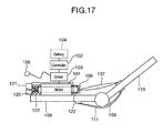
- a linear motor 101 has a controller 102, an electric driver 103, a battery 104, an electric source line 105, a connector 106, a swingable joint 108, first and second members 109 and 110 swingable with respect to each other on the joint 106, an elastic member 107 of spring or rubber whose one end is connected to a movable element through the connector 106, whose another end is connected to the second member 110 and which has an elastic characteristic for movement similar to muscle, and another elastic member 111 of spring or rubber whose one end is connected to the first member, whose another end is connected to the second member 110 and which has an elastic characteristic for movement similar to muscle.
- An electric power may be supplied to the linear motor 101 from either the battery 104 or electric source line 105. At least one of the battery 104 and electric source line 105 may be detachable.
- a spring 120 may be arranged between the first member 109 and the movable element as a damper.
- the linear motor 101 may has a cooling device 121 and/or a dust cover 122 for covering a portion of the movable element projecting from a stator.
- the cooling device 121 may be a motor drive fan or cooling fin.
- a closed-loop control system may be formed by a sensor 123 for measuring the relative movement of the movable member and the stator and/or a positional relationship between magnetic poles on the movable member and magnetic poles on the stator, the controller 102 receiving signals from the sensor 123 and the power driver 103.
- an open-loop control system may be formed by the linear motor 101, the controller 102 and the power driver 103.
- the power driver 103 may be controlled on the basis of the positional relationship between magnetic poles on the movable member and magnetic poles on the stator estimated in the controller 102 from an induced voltage E0 generated by the linear motor 101.
- the power driver 103 may be controlled on the basis of the positional relationship between magnetic poles on the movable member and magnetic poles on the stator estimated in the controller 102 from the induced voltage E0 calculated from a voltage and a measured electric current supplied to the linear motor 101.
- a relative movement between the first and second members may be brought about by a pair of the linear motors 101.
- the linear motors 101 may be selectively connected to one of the elastic members 107a and 107b to drive the second member 110 in either direction.
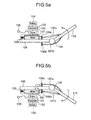
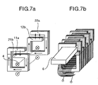
- a first magnetic core 51 forms a first pair of magnetic poles 11a and 21b
- a second magnetic core 52 forms a second pair of magnetic poles 12b and 22a
- a (2n-1)th magnetic core has the first pair of magnetic poles 11a and 21b
- the first magnetic core 51 and second magnetic core 52 are surrounded by a single electromagnetic coil 4.
- a movable member 6 including pairs of magnetic poles whose pitch Pm is equal to a pitch Ps between the first magnetic cores 51 and 52 adjacent to each other in a movable direction of the movable member 6 is movable in a gap 8 between the magnetic poles 11a and 21b of the first magnetic core 51 and between the magnetic poles 12b and 22a of the second magnetic core 52.
- the magnetic poles of the movable member 6 are formed by permanent magnets, electromagnetic coils and/or differences in magnetic conductivity relative to the magnetic cores along the movable direction. Magnetic polar directions of the first and second magnetic cores 51 and 52 adjacent to each other in the movable direction are opposite to each other.
- the magnetic cores 51 and 52 may be formed by a stack of steel plates.
- a stator 3 including the magnetic cores 51 and 52 and the electromagnetic coil 4 may be contained by various shape molded plastic.
- the movable member 6 may be rectangular or cylindrical as shown in Fig. 12.
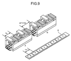
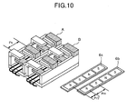
- the stator 3 has stator parts A and B arranged in series each of which stator parts includes the magnetic cores 51 and 52 and the electromagnetic coil 4 and which are energized to be magnetized respectively with a difference in energized phase between the stator parts A and B so that a travelling magnetic field for urging the movable element 6 in the movable direction is generated by a cooperation between the stator parts A and B.
- the difference in energized phase between the stator parts A and B is ⁇ /2 when the linear motor is a two phase linear motor.
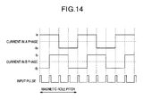
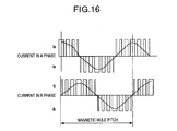
- an electric current supplied to each of the stator parts A and B may be changed along a sine curve.
- the electric current supplied to each of the stator parts A and B may changed by changing a pulse width of voltage or current to be supplied.
- the stator parts A and B may be arranged in parallel, and the movable members 6 may be arranged in parallel.
- the movable members 6 arranged in parallel may be one-piece.
- the linear motor may be three, four or five phase linear motor.
- a distance between the pair of magnetic poles of one of the stator parts and the pair of magnetic poles of another one of the stator parts adjacent to each other in the movable direction (k*P) + (P/M), when P is a pitch Ps of the pairs of the magnetic poles of the stator parts A and B adjacent to each other in the movable direction in each of the stator parts and a pitch Pm of the magnetic poles of the movable member 6 adjacent to each other in the movable direction, k is an integral number not less than zero, and M is a number of the stator parts energized with respective energized phases different from each other while M is an integral number not less than two.
- the movable member 6 may have a base band 16 and magnetically conductive protrusions 13 to change a reluctance between the movable member 6 and the magnetic cores 51 and 52 in a longitudinal direction of the movable member 6.
- the magnetically conductive protrusions 13 may be magnetized by permanent magnets on the movable member 6.
- the base band 16 may be non-magnetically permeable.
- the movable member 6 may be formed by a rod 35, high-magnetic-conductivity large diameter rings 36 and low-magnetic-conductivity small diameter rings 37.
- the rings 36 may include permanent magnets. Surfaces of the magnetic cores 51 and 52 are curved along outer surfaces of the high-magnetic-conductivity large diameter rings 36.
- the magnetic cores 51 and 52 may have slide supports 14, and the movable member 6 may have a slider 15 which can slide on the slide supports 14 with low friction.
Landscapes
- Engineering & Computer Science (AREA)
- Physics & Mathematics (AREA)
- Chemical & Material Sciences (AREA)
- Combustion & Propulsion (AREA)
- Electromagnetism (AREA)
- Power Engineering (AREA)
- Robotics (AREA)
- Mechanical Engineering (AREA)
- Linear Motors (AREA)
- Manipulator (AREA)
- Control Of Linear Motors (AREA)
- Connection Of Motors, Electrical Generators, Mechanical Devices, And The Like (AREA)
Applications Claiming Priority (2)
| Application Number | Priority Date | Filing Date | Title |
|---|---|---|---|
| JP2000342379A JP3758496B2 (ja) | 2000-11-06 | 2000-11-06 | 関節駆動装置 |
| JP2000342379 | 2000-11-06 |
Publications (1)
| Publication Number | Publication Date |
|---|---|
| EP1204196A2 true EP1204196A2 (de) | 2002-05-08 |
Family
ID=18816949
Family Applications (1)
| Application Number | Title | Priority Date | Filing Date |
|---|---|---|---|
| EP01107951A Withdrawn EP1204196A2 (de) | 2000-11-06 | 2001-03-28 | Gelenkantrieb |
Country Status (7)
| Country | Link |
|---|---|
| US (1) | US6703725B2 (de) |
| EP (1) | EP1204196A2 (de) |
| JP (1) | JP3758496B2 (de) |
| KR (1) | KR20020035420A (de) |
| CN (1) | CN1353495A (de) |
| CA (1) | CA2342962A1 (de) |
| TW (1) | TW517435B (de) |
Cited By (1)
| Publication number | Priority date | Publication date | Assignee | Title |
|---|---|---|---|---|
| WO2010114488A1 (en) * | 2009-03-31 | 2010-10-07 | Agency For Science, Technology And Research | Active manipulator |
Families Citing this family (10)
| Publication number | Priority date | Publication date | Assignee | Title |
|---|---|---|---|---|
| JP3395155B2 (ja) * | 1999-05-07 | 2003-04-07 | 株式会社日立製作所 | リニアモータ及びその製造方法 |
| JP3821101B2 (ja) | 2003-02-04 | 2006-09-13 | 株式会社日立製作所 | 直線駆動装置、その制御方法及びxyテーブル |
| KR200458256Y1 (ko) * | 2009-05-21 | 2012-01-31 | 한갑수 | 낚싯대 받침대용 주걱 |
| US9409298B2 (en) * | 2012-04-13 | 2016-08-09 | Rethink Robotics, Inc. | Flexure elements for series elastic actuators and related methods |
| CN105981262B (zh) * | 2013-09-18 | 2019-01-11 | Evr电动机有限公司 | 多极电机 |
| CN107225599A (zh) * | 2017-04-24 | 2017-10-03 | 广西柳州中嘉知识产权服务有限公司 | 关节臂测量仪 |
| CN109528362B (zh) * | 2018-12-27 | 2024-03-15 | 天衍医疗器材有限公司 | 膝关节假体 |
| CN109483588B (zh) * | 2018-12-31 | 2024-05-31 | 浙江元邦智能装备有限公司 | 一种注塑用关节机器人 |
| CN113103276B (zh) * | 2021-03-16 | 2022-12-06 | 广东省科学院智能制造研究所 | 一种柔性驱动的协作机器臂关节模块 |
| CN114940224B (zh) * | 2022-06-30 | 2023-03-07 | 哈尔滨工业大学 | 一种基于形状可重构屈曲梁驱动的爬行机器人 |
Family Cites Families (15)
| Publication number | Priority date | Publication date | Assignee | Title |
|---|---|---|---|---|
| US4293235A (en) * | 1978-04-19 | 1981-10-06 | Kabushiki Kaisha Suwa Seikosha | Structure for a linear motor for a printer |
| US4315197A (en) * | 1980-02-07 | 1982-02-09 | The United States Of America As Represented By The Administrator Of The National Aeronautics And Space Administration | Linear magnetic motor/generator |
| US4816804A (en) * | 1987-04-01 | 1989-03-28 | School Bus Parts Co. Of Canada Inc. | School bus stop sign control apparatus |
| US4945268A (en) * | 1987-12-26 | 1990-07-31 | Hitachi, Ltd. | Permanent magnet type linear pulse motor |
| DE4017600C2 (de) * | 1990-05-31 | 1998-07-02 | Siemens Ag | Handhabungsgerät für Arbeiten im Stutzenbereich eines Behälters des Primärkreises in einem Kernkraftwerk, insbesondere für zerstörungsfreie Prüfungen |
| US5426353A (en) * | 1993-03-30 | 1995-06-20 | Honeywell Inc. | Synchronous motor system employing a non-synchronous motor for enhanced torque output |
| US5740699A (en) * | 1995-04-06 | 1998-04-21 | Spar Aerospace Limited | Wrist joint which is longitudinally extendible |
| JP3791082B2 (ja) * | 1996-12-04 | 2006-06-28 | 株式会社安川電機 | リニアモータ |
| DE19652600C5 (de) * | 1996-12-18 | 2010-10-28 | Dorma Gmbh + Co. Kg | Notöffnungsvorrichtung für eine Drehfalttür oder ein Drehfalttor |
| IT1296889B1 (it) * | 1997-12-19 | 1999-08-02 | Riello Macchine Utensili Spa | Unita' di lavoro per macchina utensile con motore elettrico lineare di movimento assiale del mandrino |
| FR2784712B1 (fr) * | 1998-10-15 | 2001-09-14 | Sagem | Procede et dispositif d'actionnement electromagnetique de soupape |
| US6172437B1 (en) * | 1999-04-07 | 2001-01-09 | Black & Decker Inc. | Hybrid AC/DC motor |
| JP4061834B2 (ja) * | 2000-11-02 | 2008-03-19 | 株式会社日立製作所 | リニアモータ |
| JP4061835B2 (ja) * | 2000-11-06 | 2008-03-19 | 株式会社日立製作所 | 電動機 |
| JP3945149B2 (ja) * | 2000-11-06 | 2007-07-18 | 株式会社日立製作所 | リニアモータとその製造方法 |
-
2000
- 2000-11-06 JP JP2000342379A patent/JP3758496B2/ja not_active Expired - Fee Related
-
2001
- 2001-02-27 US US09/793,508 patent/US6703725B2/en not_active Expired - Fee Related
- 2001-03-28 EP EP01107951A patent/EP1204196A2/de not_active Withdrawn
- 2001-04-03 TW TW090108008A patent/TW517435B/zh not_active IP Right Cessation
- 2001-04-04 CA CA002342962A patent/CA2342962A1/en not_active Abandoned
- 2001-04-24 KR KR1020010022088A patent/KR20020035420A/ko not_active Withdrawn
- 2001-04-30 CN CN01117493A patent/CN1353495A/zh active Pending
Cited By (1)
| Publication number | Priority date | Publication date | Assignee | Title |
|---|---|---|---|---|
| WO2010114488A1 (en) * | 2009-03-31 | 2010-10-07 | Agency For Science, Technology And Research | Active manipulator |
Also Published As
| Publication number | Publication date |
|---|---|
| JP3758496B2 (ja) | 2006-03-22 |
| TW517435B (en) | 2003-01-11 |
| CA2342962A1 (en) | 2002-05-06 |
| KR20020035420A (ko) | 2002-05-11 |
| US6703725B2 (en) | 2004-03-09 |
| CN1353495A (zh) | 2002-06-12 |
| JP2002144274A (ja) | 2002-05-21 |
| US20020053832A1 (en) | 2002-05-09 |
Similar Documents
| Publication | Publication Date | Title |
|---|---|---|
| US4318038A (en) | Moving-coil linear motor | |
| JP3771543B2 (ja) | リニアモータ駆動装置 | |
| US5955798A (en) | Linear motor | |
| US6703725B2 (en) | Joint driving apparatus | |
| JPH0734646B2 (ja) | リニアモータ | |
| JPS6124907B2 (de) | ||
| KR101798548B1 (ko) | 선형 전동기 | |
| JP2650438B2 (ja) | パルスモータ | |
| JP2663533B2 (ja) | パルスモータ | |
| JP2642240B2 (ja) | リニアモータ | |
| JPH1169763A (ja) | シャフト型リニアモータ及びその駆動方法 | |
| KR20130008725A (ko) | 전동기 | |
| JP2002096233A (ja) | リニアスライダ | |
| JPH08275495A (ja) | リニアモータ | |
| KR20010044157A (ko) | 브러쉬없는 코일 코어형 리니어모터 및 이 리니어모터가구비된 선형구동장치 | |
| JP4352483B2 (ja) | 三相パルスモータ | |
| KR20010035213A (ko) | 브러쉬없는 평판형 공심형 교류식 리니어모터 및 그모터가 구비된 선형 구동 시스템 | |
| JP2782847B2 (ja) | パルスモータ | |
| SU1432683A1 (ru) | Линейный двигатель посто нного тока | |
| JP3211258B2 (ja) | 可動磁石型リニアモータ | |
| JP2782830B2 (ja) | リニアサーボモータ | |
| US4668883A (en) | Linear pulse motor | |
| JPS6334469Y2 (de) | ||
| RU2072614C1 (ru) | Электродвигатель с постоянными магнитами | |
| JPH06105530A (ja) | リニアモータ |
Legal Events
| Date | Code | Title | Description |
|---|---|---|---|
| PUAI | Public reference made under article 153(3) epc to a published international application that has entered the european phase |
Free format text: ORIGINAL CODE: 0009012 |
|
| AK | Designated contracting states |
Kind code of ref document: A2 Designated state(s): AT BE CH CY DE DK ES FI FR GB GR IE IT LI LU MC NL PT SE TR |
|
| AX | Request for extension of the european patent |
Free format text: AL;LT;LV;MK;RO;SI |
|
| STAA | Information on the status of an ep patent application or granted ep patent |
Free format text: STATUS: THE APPLICATION HAS BEEN WITHDRAWN |
|
| 18W | Application withdrawn |
Effective date: 20040423 |