EP1204263A1 - Méthode et système pour acheminer des appels téléphoniques - Google Patents
Méthode et système pour acheminer des appels téléphoniques Download PDFInfo
- Publication number
- EP1204263A1 EP1204263A1 EP00123872A EP00123872A EP1204263A1 EP 1204263 A1 EP1204263 A1 EP 1204263A1 EP 00123872 A EP00123872 A EP 00123872A EP 00123872 A EP00123872 A EP 00123872A EP 1204263 A1 EP1204263 A1 EP 1204263A1
- Authority
- EP
- European Patent Office
- Prior art keywords
- telephone
- mobile phone
- central office
- identifier
- cradle
- Prior art date
- Legal status (The legal status is an assumption and is not a legal conclusion. Google has not performed a legal analysis and makes no representation as to the accuracy of the status listed.)
- Withdrawn
Links
- 238000000034 method Methods 0.000 title claims description 5
- 230000000881 depressing effect Effects 0.000 description 2
- 238000013475 authorization Methods 0.000 description 1
- 230000000994 depressogenic effect Effects 0.000 description 1
Images


Classifications
-
- H—ELECTRICITY
- H04—ELECTRIC COMMUNICATION TECHNIQUE
- H04M—TELEPHONIC COMMUNICATION
- H04M3/00—Automatic or semi-automatic exchanges
- H04M3/42—Systems providing special services or facilities to subscribers
- H04M3/42229—Personal communication services, i.e. services related to one subscriber independent of his terminal and/or location
-
- H—ELECTRICITY
- H04—ELECTRIC COMMUNICATION TECHNIQUE
- H04M—TELEPHONIC COMMUNICATION
- H04M2207/00—Type of exchange or network, i.e. telephonic medium, in which the telephonic communication takes place
- H04M2207/18—Type of exchange or network, i.e. telephonic medium, in which the telephonic communication takes place wireless networks
-
- H—ELECTRICITY
- H04—ELECTRIC COMMUNICATION TECHNIQUE
- H04M—TELEPHONIC COMMUNICATION
- H04M2207/00—Type of exchange or network, i.e. telephonic medium, in which the telephonic communication takes place
- H04M2207/20—Type of exchange or network, i.e. telephonic medium, in which the telephonic communication takes place hybrid systems
-
- H—ELECTRICITY
- H04—ELECTRIC COMMUNICATION TECHNIQUE
- H04M—TELEPHONIC COMMUNICATION
- H04M2242/00—Special services or facilities
- H04M2242/30—Determination of the location of a subscriber
-
- H—ELECTRICITY
- H04—ELECTRIC COMMUNICATION TECHNIQUE
- H04M—TELEPHONIC COMMUNICATION
- H04M7/00—Arrangements for interconnection between switching centres
- H04M7/12—Arrangements for interconnection between switching centres for working between exchanges having different types of switching equipment, e.g. power-driven and step by step or decimal and non-decimal
Definitions
- the present invention relates to telephone communication systems.
- a personal number is assigned to each subscriber.
- the subscriber periodically informs a central office of a telephone number to which bis telephone calls are to be directed. This is accomplished by the subscriber sending a message to the central office. Typically, this message is sent by the subscriber depressing a long sequence of keys on his mobile phone's keypad. The sequence usually involves a telephone number for contacting the provider, an authorization code previously provided to the subscriber, and the telephone number of the selected telephone. An individual wishing to phone the subscriber dials the subscribers personal number. The central office, upon receiving the call, directs the call to the last telephone number of which the subscriber has informed the central office.
- U. S. Patent No. 5,909,650 for example, describes such a telephone service based upon a single personal number.
- the present invention provides a device and system for allowing a subscriber to inform the central office to which telephone his phone calls are to be directed.
- a device referred to herein as a "mobile phone cradle" or simply a “cradle” is placed adjacent to each telephone in a telephone network.
- the mobile phone cradle is used by a mobile phone subscriber to inform the central office to direct his calls to the telephone adjacent to the cradle.
- the cradle is configured to communicate with a subscriber's mobile phone.
- the mobile phone communicates with the cradle upon being placed in a socket located on the surface of the cradle configured to receive a mobile phone.
- communication between the cradle and the mobile phone is wireless.
- the cradle may comprise a memory for storing data such as the telephone number of the adjacent telephone.
- An input device such as a keyboard may be used to input data into the memory.
- a subscriber wishing to have his telephone calls directed to the adjacent telephone communicates an identifier of his mobile phone to the cradle.
- the identifier may be, for example, the telephone number of the mobile phone or any other unique number associated with the mobile phone.
- the identifier is communicated to the cradle either by placing the mobile phone in the socket of the cradle, or, in the case of wireless communication by bringing the mobile phone into proximity with the cradle and possibly depressing a predetermined sequence of keys on the mobile phone's keypad.
- a processor located in the cradle recalls from the memory the telephone number of the adjacent telephone to which the calls are to be directed. The processor then transmits a message to a central office indicating that telephone calls for the subscriber indicating that telephone calls for the subscriber are to be directed to the telephone adjacent to the cradle.
- the message may be transmitted over any communications network such as a wired or wireless telephone system, a computer network such as the Internet or an intranet, or by satellite communication.
- the central office upon receiving a call directed to the subscriber, directs the call to the adjacent telephone as is known in the art, for example, as disclosed in U.S. Patent No. 5,909,650.
- the present invention provides a device configured to communicate with a mobile telephone and further configured to communicate with a central office maintaining a database of subscribers including, for each subscriber, one or more identifiers of at least one mobile phone associated with the subscriber.
- the invention provides a system for directing an individual's telephone calls to a selected telephone, the system comprising a device according to the invention.
- the invention provides a method for directing an individual's telephone calls to a selected telephone, the individual having a mobile telephone, the method comprising steps of
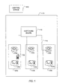
- the system includes one or more telephone networks such as the telephone network 115, and possibly others (not shown).
- Each telephone system includes a plurality of telephones 105 such as the wired telephones 105a, 105b, and 105c.
- the network 115 is coupled to a switching board 110.
- Telephones 105a, 105b, and 105c are located in locations 120a, 120b, and 120c, respectively.
- adjacent to each telephone 105 is a mobile phone cradle 125.
- the mobile phone cradle 125 is used by a subscriber to inform a central office 140 to direct his phone calls to the telephone 105 adjacent to the cradle 125.
- a mobile telephone 130 may be carried anywhere by the subscriber, but is shown to be in the location 120a.
- the cradle 125 communicates to the central office 140 in order to inform the central office 140 to which telephone the subscriber's calls are to be directed.
- Communication between the cradle 125 and the central office 140 may be over any communications network such as a wired or wireless telephone system, a computer network such as the Internet or an intranet, or by satellite communication.
- Fig. 2a shows one embodiment of the mobile phone cradle 125.
- the cradle communicates with the mobile phone 130.
- the cradle 125 has a socket 200 configured to receive a mobile telephone such as the mobile telephone 130.
- An input device such as a keyboard 220 is used to input data into a memory 310 to be described in reference to Fig. 4.
- the data may be, for example, the telephone number of the adjacent telephone 105.
- a subscriber arriving at the location 120a for example, with his mobile phone 130, and wishing to have his incoming telephone calls directed to the telephone 105a, places his mobile phone 130 in the socket 200 of the cradle 125a adjacent to the telephone 125a, as shown in Fig. 2b.
- Conducting contacts 225 at the bottom of the socket 200 are configured to contact serial output contacts of a mobile phone such as the mobile phone 130, when the mobile phone is in the socket 200 of the cradle 125. This allows communication between the mobile phone 130 and a processor 300 located inside the cradle 125, to be described in reference to Fig. 4.
- the cradle 125 may be connected to an external power source by a cable 230.
- Fig. 3 shows a second embodiment of the cradle 125.
- This embodiment has features in common with the embodiment of Fig. 2, and Similar components have been given the same reference numeral.
- This embodiment differs from the embodiment of Fig. 2 in that the cradle 125 of Fig. 3 is configured to communicate with the mobile phone 130 wirelessly.
- the mobile phone 130 has been configured to contain a chip capable of transmitting to the cradle of Fig. 3 an identifier when the phone 130 is brought into proximity with the cradle 125 of Fig. 3.
- the identifier may be transmitted automatically when the mobile phone 130 is brought into proximity with the cradle 125, or a predetermined key or sequence of keys may be depressed on a keypad 320 of the phone 130 or on the keyboard 220 of the cradle 125.
- the cradle 125 of Fig. 3 has a receiver 330, to be described in reference to Fig. 4b, to receive this information.
- Fig. 4a shows the internal structure of the cradle 125 of Fig. 2.
- the contacts 225 are connected to the processor 300 that thus receives from the mobile phone 130 an identifier of the mobile phone 130 when the phone 130 is in the socket 200.
- the identifier may be, for example, the telephone number of the phone 130, or another number unique to the phone 130.
- the processor 300 recalls from the memory 310 the telephone number of the adjacent telephone, for example, the telephone 105a.
- the processor transmits a message to the central office 140 as described above with reference to Fig. 1, indicating that telephone calls for the mobile phone 130 are to be directed to the telephone 105a.
- the message may be transmitted using the mobile phone 130 in the socket 200 of the cradle.
- the central office Upon receiving this information from the cradle, the central office updates its database to indicate the current telephone to which the subscriber's calls are to be directed.
- the central office 140 upon receiving a call directed to the subscriber, directs the call to the switching board 110 of the telephone network 115 with instructions to direct the call to the telephone 105a.
- the subscriber When the subscriber is ready to leave the location 120a, and no longer wishes to direct his phone calls to the phone 105a, he communicates this to the cradle, for example, by removing the mobile phone 130 from the socket 200 of the cradle 125a.
- the processor 300 transmits a message to the central office 130 that calls to the mobile phone 130 are to be directed to a predetermined default telephone such as the mobile phone 130.
- Fig. 4b shows the internal structure of the cradle 125 of Fig. 3.
- the internal structure of the cradle of Fig. 3 is similar to that of Fig. 2, and similar components have been given the same identifying numeral.
- this cradle contains the receiver 330 that receives information relating to an identifier of the mobile phone 130 from the mobile phone 130. The information is sent to the processor 300.
- the processor 300 recalls from the memory 310 the telephone number of the adjacent telephone, for example, the telephone 105a.
- the processor transmits a message to the central office 140 as described above with reference to Fig. 1, indicating that telephone calls for the mobile phone 130 are to be directed to the telephone 105a.
- the message may be transmitted over a phone line 240 such as the phone line of the telephone 105a, where it is processed as described above in reference to Fig. 4a.
Landscapes
- Engineering & Computer Science (AREA)
- Signal Processing (AREA)
- Mobile Radio Communication Systems (AREA)
Priority Applications (1)
| Application Number | Priority Date | Filing Date | Title |
|---|---|---|---|
| EP00123872A EP1204263A1 (fr) | 2000-11-02 | 2000-11-02 | Méthode et système pour acheminer des appels téléphoniques |
Applications Claiming Priority (1)
| Application Number | Priority Date | Filing Date | Title |
|---|---|---|---|
| EP00123872A EP1204263A1 (fr) | 2000-11-02 | 2000-11-02 | Méthode et système pour acheminer des appels téléphoniques |
Publications (1)
| Publication Number | Publication Date |
|---|---|
| EP1204263A1 true EP1204263A1 (fr) | 2002-05-08 |
Family
ID=8170274
Family Applications (1)
| Application Number | Title | Priority Date | Filing Date |
|---|---|---|---|
| EP00123872A Withdrawn EP1204263A1 (fr) | 2000-11-02 | 2000-11-02 | Méthode et système pour acheminer des appels téléphoniques |
Country Status (1)
| Country | Link |
|---|---|
| EP (1) | EP1204263A1 (fr) |
Citations (2)
| Publication number | Priority date | Publication date | Assignee | Title |
|---|---|---|---|---|
| EP0520194A2 (fr) * | 1991-06-28 | 1992-12-30 | Network Access Corporation | Système personnel de télécommunication |
| EP0536949A2 (fr) * | 1991-10-09 | 1993-04-14 | AT&T Corp. | Technique de détournement de communications entrantes utilisant un indicateur de la position de l'abonné appelé |
-
2000
- 2000-11-02 EP EP00123872A patent/EP1204263A1/fr not_active Withdrawn
Patent Citations (2)
| Publication number | Priority date | Publication date | Assignee | Title |
|---|---|---|---|---|
| EP0520194A2 (fr) * | 1991-06-28 | 1992-12-30 | Network Access Corporation | Système personnel de télécommunication |
| EP0536949A2 (fr) * | 1991-10-09 | 1993-04-14 | AT&T Corp. | Technique de détournement de communications entrantes utilisant un indicateur de la position de l'abonné appelé |
Similar Documents
| Publication | Publication Date | Title |
|---|---|---|
| US6553221B2 (en) | Incoming call notification apparatus | |
| CA2226245C (fr) | Systemes cellules et methodes de demande de secours | |
| JPH07327261A (ja) | ハンドセットの基地局登録の基地局格納方法 | |
| EP0766442B1 (fr) | Procédé de télécommunication et appareil approprié à sa mise en oeuvre | |
| KR20010073077A (ko) | 이동 전화 장치 및 호출 전환 서비스 방법 | |
| US20020090926A1 (en) | Context-based checking method and arrangement for communications, a communications network and a terminal of a communications network | |
| EP0921668B1 (fr) | Système et méthode de communication AMRT | |
| EP0944277B1 (fr) | Procédé et système d'affectation de plusieurs numéros d'annuaire à un téléphone d'un système personel de télécommunications | |
| US6754317B1 (en) | Telephony access using an email address | |
| EP1204263A1 (fr) | Méthode et système pour acheminer des appels téléphoniques | |
| KR100593608B1 (ko) | 무선 교환시스템에서 무선 핸드셋과 전화기 본체간의연결 방법 | |
| JP2742689B2 (ja) | 移動体位置登録方式 | |
| KR19990004344A (ko) | 이동통신시스템의 사용자 고유번호를 이용한 휴대기 사용방법 | |
| US20020016184A1 (en) | Automatic method of managing network services | |
| KR20040012284A (ko) | 이동통신 단말기의 단문 메시지 서비스를 이용한 통화 중전화부 관리 방법 | |
| KR100221058B1 (ko) | 개인번호를 이용한 호 자동접속시스템 및 호 자동접속방법 | |
| US5828745A (en) | Call processing method adapted for deleting a misdialed digit | |
| JPH0918584A (ja) | 構内電話システム | |
| KR100258501B1 (ko) | 개인통신가입자 부가서비스 원격기능제어방법 | |
| US6374113B1 (en) | Dynamic call coverage paths based on terminal location | |
| KR100307695B1 (ko) | 착신측 이동 단말기에 대한 무선 데이타 서비스 가능상태 확인방법 | |
| KR100598580B1 (ko) | 부가 전화번호 서비스 시스템 및 방법 | |
| JP2000125348A (ja) | 無線電話システム | |
| KR100389826B1 (ko) | 무선 사설교환시스템 운용상태 표시방법 | |
| JP3003644B2 (ja) | 小規模加入者向けpbx接続方式 |
Legal Events
| Date | Code | Title | Description |
|---|---|---|---|
| PUAI | Public reference made under article 153(3) epc to a published international application that has entered the european phase |
Free format text: ORIGINAL CODE: 0009012 |
|
| AK | Designated contracting states |
Kind code of ref document: A1 Designated state(s): AT BE CH CY DE DK ES FI FR GB GR IE IT LI LU MC NL PT SE TR |
|
| AX | Request for extension of the european patent |
Free format text: AL;LT;LV;MK;RO;SI |
|
| AKX | Designation fees paid | ||
| REG | Reference to a national code |
Ref country code: DE Ref legal event code: 8566 |
|
| STAA | Information on the status of an ep patent application or granted ep patent |
Free format text: STATUS: THE APPLICATION IS DEEMED TO BE WITHDRAWN |
|
| 18D | Application deemed to be withdrawn |
Effective date: 20021109 |