EP1204272A1 - Scanneur alimente par un port de bus série universel - Google Patents
Scanneur alimente par un port de bus série universel Download PDFInfo
- Publication number
- EP1204272A1 EP1204272A1 EP01309288A EP01309288A EP1204272A1 EP 1204272 A1 EP1204272 A1 EP 1204272A1 EP 01309288 A EP01309288 A EP 01309288A EP 01309288 A EP01309288 A EP 01309288A EP 1204272 A1 EP1204272 A1 EP 1204272A1
- Authority
- EP
- European Patent Office
- Prior art keywords
- sensing module
- illumination source
- motion mechanism
- image sensing
- illumination
- Prior art date
- Legal status (The legal status is an assumption and is not a legal conclusion. Google has not performed a legal analysis and makes no representation as to the accuracy of the status listed.)
- Withdrawn
Links
Images



Classifications
-
- H—ELECTRICITY
- H04—ELECTRIC COMMUNICATION TECHNIQUE
- H04N—PICTORIAL COMMUNICATION, e.g. TELEVISION
- H04N1/00—Scanning, transmission or reproduction of documents or the like, e.g. facsimile transmission; Details thereof
- H04N1/024—Details of scanning heads ; Means for illuminating the original
-
- G—PHYSICS
- G06—COMPUTING OR CALCULATING; COUNTING
- G06V—IMAGE OR VIDEO RECOGNITION OR UNDERSTANDING
- G06V10/00—Arrangements for image or video recognition or understanding
- G06V10/10—Image acquisition
-
- H—ELECTRICITY
- H04—ELECTRIC COMMUNICATION TECHNIQUE
- H04N—PICTORIAL COMMUNICATION, e.g. TELEVISION
- H04N1/00—Scanning, transmission or reproduction of documents or the like, e.g. facsimile transmission; Details thereof
- H04N1/00127—Connection or combination of a still picture apparatus with another apparatus, e.g. for storage, processing or transmission of still picture signals or of information associated with a still picture
- H04N1/00204—Connection or combination of a still picture apparatus with another apparatus, e.g. for storage, processing or transmission of still picture signals or of information associated with a still picture with a digital computer or a digital computer system, e.g. an internet server
- H04N1/00236—Connection or combination of a still picture apparatus with another apparatus, e.g. for storage, processing or transmission of still picture signals or of information associated with a still picture with a digital computer or a digital computer system, e.g. an internet server using an image reading or reproducing device, e.g. a facsimile reader or printer, as a local input to or local output from a computer
-
- H—ELECTRICITY
- H04—ELECTRIC COMMUNICATION TECHNIQUE
- H04N—PICTORIAL COMMUNICATION, e.g. TELEVISION
- H04N1/00—Scanning, transmission or reproduction of documents or the like, e.g. facsimile transmission; Details thereof
- H04N1/46—Colour picture communication systems
- H04N1/48—Picture signal generators
- H04N1/482—Picture signal generators using the same detector device sequentially for different colour components
- H04N1/484—Picture signal generators using the same detector device sequentially for different colour components with sequential colour illumination of the original
Definitions
- the present invention generally relates to a scanning system and more particularly relates to a mobile scanner capable of scanning both transparent and opaque materials that itself does not have a separate processor and is not energized by a separate power supply, wherein the power required to support the operation of the mobile scanner is derived from a universal serial bus (USB) connection with a computing device.
- USB universal serial bus
- optical scanners there are many applications that need optical scanners to convert paper-based objects, such as texts and graphics, to an electronic format that can be subsequently analyzed, distributed and archived.
- One of the most popular optical scanners is flatbed scanners that convert scanning objects, including pictures and papers, to images that can be used, for example, for building World Wide Web pages and optical character recognition.
- Another popular optical scanner is what is called sheet-fed scanners that are small and unobtrusive enough to sit between a keyboard and a computer monitor or integrated into a keyboard to provide a handy scanning means.
- Most optical scanners are referred to as image scanners as the output thereof is generally in digital image format.
- sheet-fed scanners such as those Paper Port series from Visioneer Inc.
- the sheet-fed scanners gradually replace handheld scanners. Because a sheet-fed scanner operates automatically, namely a scanning document is well controlled to pass through an image sensor in the sheet-fed scanner; the resultant images are generally satisfactory.
- a typical sheet-fed scanner has a micro-processor, memory, post-processing circuitry and interface circuitry. Further to energize all the parts in the scanner, there is an external power adapter converting a high AC voltage to a low DC voltage. With all the parts together, a sheet-fed scanner is indeed a self-contained system having an interface to a computing system.
- the micro-processor in use is typically an 8-bit microprocessor, for example, 8088 from Intel, which is considered nowadays a primitive processor in light of available 32-bit or even 64-bit microprocessors.
- the overall system performance is thus severely limited by the performance of an 8-bit microprocessor.
- a portable scanner device capable of being powered through a universal serial bus connection where the individual components of the portable scanner are selectively and controllably powered so as to function within the power limitations of a universal serial bus connection port (e.g. 5 Volts, 2.2 watts) without appreciable degradation of a captured image whether that image resides on a transparent media (i.e., a negative) or an opaque media (i.e., paper).
- a universal serial bus connection port e.g. 5 Volts, 2.2 watts
- the scanner itself comprises an image sensing module, a motion mechanism and an interface engine.
- the scanner is not powered by an external power adapter rather it is powered through a universal serial connection to a host computer.
- the image sensing module including a one-dimensional image sensor, an optical system, a first illumination source (for opaque scanning) and optionally a second illumination source (for transparent scanning), is responsible for imaging content containing media such as a document.
- the motion mechanism is responsible for moving the document through the image sensing module at a steady speed. Both of the image sensing module and the motion mechanism are coupled to the interface engine that comprises a control circuit. In operation, the circuit receives system control signals from the computing device through the universal serial connection.
- the interface engine draws a power supply from the computing device through a universal serial bus to selectively and controllably energize the image sensing module and the motion mechanism to operate.
- the disclosed scanner comprises two demountable cases.
- the main case houses the image sensing module and the motion mechanism and the base case houses the second illumination source.
- the first illumination source in the image sensing module provides front illumination to an opaque scanning object while the second illumination source provides back illumination to a transparent scanning object, as such the disclosed scanner is capable of scanning both opaque and transparent materials, a dual scanning feature that has been long sought in the scanning market.
- one of the objects in the present invention is to provide a mobile scanner that is of high performance and low cost and so lightweight that it can be used in any conditions.
- FIG. 1 shows a schematic configuration in which the present invention may be practiced.
- Mobile scanner 100 is connected, through a universal serial bus cable 113 to a compatible universal serial bus port (not shown) on a computing device 102.
- Computing device 102 which may be an IBM PC or PC-compatible notebook computer includes an USB port coupled to the PC bus and controlled by a microprocessor in the computing device.
- the microprocessor is typically a 32-bit microprocessor such as a Pentium III processor from Intel Corporation.
- Scanner 100 scans, line by line, a scanning object 110, such as a piece of paper or film with text and/or graphics on it.
- the scanning result which is typically a digital representation of scanning object 110, is transferred to computer 102 through universal serial bus cable 113.
- the digital representation may be converted by the application program to a standard image format such as TIFF (Tag Image File Format) or BMP (Bitmap File Format), that may be manipulated for desired visual effects by another application program, such as PhotoShop 5.0 from Adobe Systems.
- the digital representation or manipulated digital image can be displayed on display monitor 104.
- Computing device 102 is further provided with one or more removable storage devices which may be read or written to, a fixed disk drive (not shown) for storing image files and application program files, a keyboard 106 for permitting input of text data, such as titles and names for scanned image files, and a pointing device 108 such as a mouse or the like which is also provided to permit execution of commands, for example, to display the scanned object and manipulated images thereof on display monitor 104.
- a fixed disk drive not shown
- keyboard 106 for permitting input of text data, such as titles and names for scanned image files
- a pointing device 108 such as a mouse or the like which is also provided to permit execution of commands, for example, to display the scanned object and manipulated images thereof on display monitor 104.
- FIG. 2 shows a systemic diagram of a prior art scanner 200 that converts a paper-based scanning object 220 to a corresponding digital image 222.
- Scanner 200 comprises an image sensing module 204, an analog-to-digital circuitry 206, a motion mechanism 208, a microprocessor 210 and memory 212.
- Motion mechanism 208 is controlled by microprocessor 210 which works in synchronization with image sensing module 204 such that image sensing module 204 images scanning object 220 while passing through image sensing module 204 at a steady speed.
- Image signals from image sensing module 204 are then digitized by analog-to-digital circuitry 206 to produce digital signals (raw data) representing scanning object 220.
- scanner 200 further comprises a post-signal processing circuitry 214 and an interface 216.
- Post-signal processing circuitry 214 generally performs digital signals enhancement and often presents the digital signals in a standard image format, such as TIFF or BMP.
- Interface 216 prepares the images for real-time transmissions through a standard interface, such as IEEE RS-232, via a serial port to a computing device.
- power supply 218, typically heavy and bulky, is provided to scanner 200 to energize all the parts in scanner 200 to operate.
- Mobile scanner 300 comprises fewer components than found in scanner 200 of Figure 2.
- the principle components of scanner 300 are an image sensing module 304 and a motion mechanism 312. It should be noted that there is no separate power supply to energize image sensing module 304 and motion mechanism 312 to work. The elimination of a separate power supply will considerably reduce the overall weight, size and portability of a scanner.
- the power for image sensing module 304 and motion mechanism 312 is derived from computing device 302 with which scanner 300 operates.
- Image sensing module 304 comprises an image sensor 306, an optical lens 308 and an illumination system 310.
- image sensor 306 is an array of Complementary Metal-Oxide Semiconductor (CMOS) photodetectors, each producing a charge signal when being exposed to incident light.
- CMOS Complementary Metal-Oxide Semiconductor
- Optical lens 308 collects incident light from a scanned object illuminated by illumination source 310 onto image sensor 306, thereby an image of the scanning object is produced.
- Motion mechanism 312 is responsible for moving the scanning object through image sensor 306 so that the entire scanning object can be scanned.
- both image sensing module 302 and motion mechanism 304 are housed in a compact case that can be made of a kind of light but rigid plastic material.
- An interface engine such as USB interface 316 houses all the electronic components such as A/D converter, a processor, memory and etc. to control image sensing module 302 and motion mechanism 304 to operate synchronously in addition to support data communication with a host computing device.
- the interface engine may be housed in the same compact case that houses image sensing module 302 and motion mechanism 304.
- the interface engine may be housed in a separate case, shown in the figure, connected to the serial connection cable.
- Other possible embodiments include an integration of the interface engine with the serial connection cable.
- Figure 4A shows a cross-section view of a mobile scanner 400 according to the present invention and mobile scanner 400 may correspond to mobile scanner 100 of Figure 1.
- scanner 400 appearing rounded triangle shaped, comprises two demountable portions, a main case 402 and a base case 404, both preferably made of an identical material.
- Main case 402 houses an image sensing module 406 and motion mechanism of which only a rubber surfaced rod 408 is shown.
- a scanning object 420 is received from receiving opening 422, then moved by moving rod 408 to pass an optical path 426 and exited from exiting opening 424.
- illumination source 428 When scanning object 420 passes optical path 426, scanning object 420 is illuminated by front illumination source 428, reflected light from scanning object 420 is collected by lens 412 and focused upon image sensor 410. It is noticed that illumination source 428 is referred to as front illumination source because it provides front illumination to a scanning object that is opaque. In other words, when scanning object 420 is transparent, no reflected light can be collected from the scanning object illuminated by illumination source 428.
- Base case 404 comprises a second illumination source 432 which provides back illumination and can be removably mounted to main case 402 when there is a need to scan a scanning object that is transparent.
- the transparent sheet-like scanning object may include negative or positive films, transparencies for an overhead projector or X-ray films.
- Figure 4B and 4C demonstrate respectively the front illumination for an opaque scanning object and the back illumination for a transparent scanning object from the perspective of optics.
- scanning object 420 is an opaque scanning material, such as a piece of paper, having a front surface facing to image sensor 410.
- Front illumination source 410 illuminates the front surface of scanning object 420, light reflected from the surface is collected by optical lens 412 and focused upon image sensor 410 so that an image of the surface is obtained.
- scanning object 420 is a transparent scanning material, such as a piece of film.
- Back illumination source 432 provides illumination from the back of transparent scanning object 420 such that light transmitted through transparent scanning object 420, namely transmitted light, is collected by optical lens 412 and focused upon image sensor 410 so that an image of the transparent scanning object is obtained.
- base module 404 is one of the distinctive features of the present invention. With base module 404 mounted to main module 402, mobile scanner 400 is capable of scanning both transparent and opaque scanning document. Typically, a user uses main module 402 for scanning paper-sheet materials in which case illumination source 428 provides front illumination to the materials passing through optical path 426. When the user decides to scan transparent materials, base module 404 can be mounted onto main module 402, in which case illumination source 432 is on to provide back illumination to the transparent materials.
- a switch can be placed on the bottom of main module 402, the switch is so designed that it can be automatically turned on to switch the power supplied to illumination source 428 to illumination source 432 when base module 404 is mounted to main module 402.
- a light source (emitter) 434 and a photodetector 436 are used to detect if scanning object 420 is opaque or transparent.
- light source 434 and photodetector 436 are aligned so that photodetector 436 is always activated by light source 434.
- photodetector 436 becomes inactivated because of the blocked light source 434 by the opaque sheet.
- a control circuit not shown in the figure and understood to those skilled in the art, can automatically turn on front illumination source 428.
- photodetector 436 remains activated because light source 434 can go through the transparent sheet. Therefore the same control circuit can automatically turn on back illumination source 432.
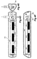
- Figures 4D to 4F illustrate a top view, a side view and a front view of the internal structure of main module 402.
- Elongated part 452 corresponds to image sensing module 406 of Figure 4A and includes an image sensor, a (front) illumination source and a rod lens array.
- Shaft 454 including one or more rubber-surfaced tube 456 is rotated by a motor 458 through a gearbox 460.
- motor 458 causes shaft 454 to rotate at a speed adjusted by gear box 460 and the scanning object is then carried along by rubber surfaced tube 456 to move against elongated part 452 so that the image sensor therein can image the scanning object completely.
- main module 402 to control the operation of the image sensor and the illumination source.
- the overall system performance of the scanner is not fixed rather depending on a host computer with which the scanner is coupled to operate.
- Universal serial bus connector 504 preferably meets the well-known Universal Serial Bus (USB) standards as defined in the Universal Serial Bus Specification Revision 1.1 which is incorporated by reference.
- Universal serial bus connector 502 includes differential data input/output (I/O) lines, a ground reference GND, as well as the integral power node all of which are preferably coupled through universal serial bus interface to the device circuits shown.
- I/O differential data input/output
- GND ground reference
- integral power node all of which are preferably coupled through universal serial bus interface to the device circuits shown.
- Read Only Memory (ROM) 508 provides information to the computing device on what functions or procedures universal serial bus interface 504 performs and what system resources (I/O, IRQ, etc) it requires.
- image sensing module 514 outputs analog signals generated from the charge signals in the photodetectors of the image sensor when image sensor is impinged with incident light (reflected or transmitted light).
- the analog signals are received by an analog-to-digital (A/D) converter 512 through an analog signal line and the resultant digitized (digital) signals are uploaded to the computing device via the universal serial bus connection.
- the illumination source in the image sensing module 514 is controlled and synchronized by control signals from control signals circuitry 506 that operates under system control signals from an associated computer device (i.e., computing device 102 of Figure 1) via USB interface 504.
- the illumination source comprises three primary colored lights, such as red, green and blue. To reproduce a color image, three primary color intensity images must be obtained.
- A/D converter 512 receives three analog signals respectively for each of the colored lights and produces respectively three digital signals.
- control signals circuitry 506 ensures that only one of the three lights is "ON" at one time for a specific period and each of the lights is successively turned on.
- motor drive5 518 receives control signals from control signals circuitry 506.
- control signals circuitry 506 is controlled by system control signals generated from the computing device via the universal serial bus connection and comprises many logic circuits so as to generate control signals with different timings.
- the system control signals are generated in the computing device that operates an application program, the application program implementing a process that uses the computing device to ultimately controls the operation of the scanner.
- USB interface 504 which typically an ASIC circuit, produces interface control signals to synchronize all parts in the interface engine.
- control signals circuitry 506 With respect to the interface control signals, control signals circuitry 506 generates a set of scanner control signals.
- Each of the scanner control signals is used to synchronize the operation of a particular part.
- three illumination control signals are generated to control the operation of the illumination source comprising the three colored lights.
- the timing in the illumination control signals is so designed that only one of the lights is turned on for a specific period at one time and the three lights are successively turned on.
- sensor control signals and motor control signals are generated with respect to the illumination control signals so that the image sensing module and the motion mechanism can work harmoniously to produce images of scanning objects.
- sequential power regulator 526 sequentially powers the system components in accordance with instructions received from control signals circuitry 506 to minimize overall power requirements.
- protection control signal there is one protection control signal from control signals circuitry 504 to motor driver 518.
- the protection control signal is used to protect the motor drive mechanism 520.
- the protection control signal can immediately cause motor drive 518 to stop the operation of the motor in drive mechanism 520.
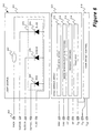
- FIG. 6 shows an internal functional diagram of sensing module 600 according to one embodiment of the present invention.
- the front illumination source comprises a red LED 604, a green LED 606 and a blue LED 608, each controlled respectively by a control signal, GLED, RLED or BLED at respective connectors.
- back illumination source 602 is shown as one light and one connector 603.
- back illumination source 602 may be implemented with a single LED or a fluorescent light controlled by an "ON" signal at connector 603, and alternatively with three colored lights similar to red LED 604, green LED 606 and blue LED 608, in which case connector 603 should be implemented with three separate connectors, and the corresponding control signals may be provided from USB interface 504 of Figure 5.
- either illumination source 602 is turned “ON” for a transparent scanning object or the LEDs are successively turned “ON” for an opaque scanning object.
- the rod lens array 610 collects either the reflected light from the opaque scanning object illuminated by one of red LED 604, green LED 606 and blue LED 608 or transmitted light from the transparent scanning object illuminated by back illumination source 602 and focuses the light onto image sensor 612.
- Image sensor 612 comprises, for example, N photodetectors. Each of the photodetectors collects light cast thereon during each integration process and generates a pixel signal. Upon the completion of the integration process, the pixel signals, each respectively generated by one of the photodetectors, are sequentially readout to the video bus 616 as a scanning signal via readout switch array 614 controlled by control signals from USB interface 504 of Figure 5. It should be noted that image sensor 612 may be a CMOS type sensor and those skilled in the art will understand that the description works the same for CCD type sensors.
- Switch array 614 comprises the same number of the readout switches as the number of the photodetectors in the image array 612. It is understood to those skilled in the art that each of the readout switches may be implemented by a diode that becomes “On” or “passing through” when a proper voltage from USB interface 504 of Figure 5 is applied across. As shown in the figure, the scanning signal is coupled to a gain & offset control circuit 618. The scanning signal is processed, including amplified and offset, in gain & offset control circuit 618 with respect to a desired adjustment and subsequently output as a signal V out to USB interface 504 of Figure 5.
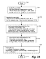
- Figures 7A to 7C show flowcharts of the process that can be used to control the operation of the interface control card and subsequently of the image sensing module and the motion mechanism and should be understood in conjunction with Figure 5.
- a compiled and linked version of the process is executed in a computing device with which the scanner operates.
- the process starts with a calibration procedure to get various calibration data that will be used to refine image raw data during actual image acquisition. Because of various practical reasons, the image sensor in the image sensing module may not produce intensity signals or valid signals from all of the photodetectors. To avoid undesirable (bad) signals, at 704, one or more lines of scanning signals are acquired to detect if there are any bad signals in the acquired scanning signals. As described above, this is done through the interface engine that produces the digital signals of the scanning signals. If there are any digital signals that have values beyond ⁇ 50% of the average of the entire line of digital signals, these pixels are marked "bad".
- the process is moved to get correct exposure times for the three respective colored lights.
- the three colored lights are red, green and blue light tubes stimulated by respective one or more red, green and blue LEDs. It is known that the sensitivity of the image sensor to the colors and the light intensities from the three colored lights are different.
- a set of calibrated timing parameters must be derived from an actual test. There can be many ways to derive this set of timing parameters. According to one implementation, the set of timing parameters is derived with respect to the maximum values in the three respective lines of signals obtained under independent and respective illumination of the three colored lights.
- the process is moved to obtain the most appropriate gain and offset from the actual signals.
- a few hundreds of lines of signals are acquired from the same scanning lines under the same lighting conditions (reduced to 5% of the adjusted full capacity). These signals are then averaged to derive an offset, referred to as BlackData, of each of the three colored lights.
- the process is moved to obtain the respective maximum values, referred to as WhiteData, from a few hundreds of lines of signals that are acquired under the same lighting conditions (adjusted full capacity). Hence a set of WhiteData and BlackData is obtained for each colored illumination.
- the process is moved to calculate the gain value, referred to as GainData, with respect to the respective obtained set of WhiteData and BlackData.
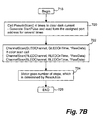
- Figure 7B shows the process (image acquisition) with the control of the illumination source and motion mechanism. It should be noted herein that the process does not have to identify which illumination source is in operation.
- a cleanup procedure is executed at 720. The purpose of cleanup procedure is to ensure that no signal residues are in the image sensor.
- the colored lights are respectively and successively turned on for a specific time by the respective exposure timing parameters obtained in the calibration process. To be specific with one implementation, the green light is kept “ON” for a duration of GLEDOntime, the red light is kept “ON” for a duration of RLEDOntime and the blue light is kept “ON” for a duration of BLEDOntime. Under each of the lighting condition, three lines of digital signals are respectively and subsequently obtained before the motion mechanism advances the scanning object for the next scanning at 724.
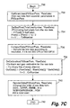
- Figure 7C shows the process for image acquisition.
- lines of image data are captured under the respective exposure timing parameters obtained in the calibration procedure.
- those marked "bad” signals are replaced using an average of neighbor signals.
- the scanner is designed to scan at a fixed resolution, for example, 300 dpi or 600 dpi. If a user decides to have an image resolution other than what the scanner can provide, the scanned digital signals are extrapolated or interpolated at 736 to produce the desired resolution. Before the digital signals are finally output, for example, for display, the digital signals are corrected with the gain and offset obtained empirically before. At 740, the corrected digital signals (image pixels) are regrouped to comply with the traditional RGB data format.
Landscapes
- Engineering & Computer Science (AREA)
- Multimedia (AREA)
- Signal Processing (AREA)
- General Engineering & Computer Science (AREA)
- Computing Systems (AREA)
- Physics & Mathematics (AREA)
- General Physics & Mathematics (AREA)
- Theoretical Computer Science (AREA)
- Facsimile Scanning Arrangements (AREA)
- Image Input (AREA)
Applications Claiming Priority (2)
| Application Number | Priority Date | Filing Date | Title |
|---|---|---|---|
| US09/705,522 US6459506B1 (en) | 1998-09-16 | 2000-11-02 | Lightweight dual-mode mobile scanner powered from a universal serial bus port |
| US705522 | 2000-11-02 |
Publications (1)
| Publication Number | Publication Date |
|---|---|
| EP1204272A1 true EP1204272A1 (fr) | 2002-05-08 |
Family
ID=24833849
Family Applications (1)
| Application Number | Title | Priority Date | Filing Date |
|---|---|---|---|
| EP01309288A Withdrawn EP1204272A1 (fr) | 2000-11-02 | 2001-11-01 | Scanneur alimente par un port de bus série universel |
Country Status (5)
| Country | Link |
|---|---|
| US (1) | US6459506B1 (fr) |
| EP (1) | EP1204272A1 (fr) |
| KR (1) | KR20020034973A (fr) |
| CN (1) | CN1367607A (fr) |
| TW (1) | TW535397B (fr) |
Cited By (1)
| Publication number | Priority date | Publication date | Assignee | Title |
|---|---|---|---|---|
| DE102010006086A1 (de) * | 2010-01-28 | 2011-08-18 | 3T Supplies Ag | Kombinierter Papier-Schredder und Stapler |
Families Citing this family (23)
| Publication number | Priority date | Publication date | Assignee | Title |
|---|---|---|---|---|
| JP3957988B2 (ja) * | 2000-05-22 | 2007-08-15 | キヤノン株式会社 | 撮像装置の制御方法 |
| US6791720B1 (en) * | 2000-07-28 | 2004-09-14 | Lite-On Technology Corporation | Portable scanning apparatus |
| US10453151B2 (en) | 2001-02-01 | 2019-10-22 | Kris Engineering, Inc. | Receipts scanner and financial organizer |
| US7746510B2 (en) | 2001-02-01 | 2010-06-29 | Pandipati Radha K C | Receipts scanner and financial organizer |
| US20020131636A1 (en) * | 2001-03-19 | 2002-09-19 | Darwin Hou | Palm office assistants |
| TWI221385B (en) * | 2001-05-31 | 2004-09-21 | Mustek Systems Inc | CCD type scanner powered by a serial bus |
| US7248387B2 (en) * | 2001-07-31 | 2007-07-24 | Umax Data Systems, Inc. | Scanning speed control device and method |
| US8218183B2 (en) * | 2001-07-31 | 2012-07-10 | Transpacific Systems, Llc | Scanning speed control device and method |
| US7202981B2 (en) * | 2001-11-01 | 2007-04-10 | Kuo-Jeng Wang | Method and system for increasing scanning speed |
| US7420715B2 (en) * | 2001-12-11 | 2008-09-02 | Transpacific Ip, Ltd. | Method and system for promoting scanning speed |
| JP2006511896A (ja) * | 2002-10-21 | 2006-04-06 | スペロ,ラファエル | 領収書および関連データの取り入れ、記憶および処理のシステムならびに方法 |
| US7460257B2 (en) * | 2002-11-04 | 2008-12-02 | Chen-Ho Lee | Technique for transferring image information from a scanning apparatus |
| CN100505813C (zh) * | 2003-03-12 | 2009-06-24 | 宇东科技股份有限公司 | 以总线电源驱动的扫描器 |
| US20050289257A1 (en) * | 2004-06-24 | 2005-12-29 | Fink Thomas M | Self-powered USB device with USB power line reset and related USB host and USB system |
| US20060012819A1 (en) * | 2004-07-13 | 2006-01-19 | Haas William R | Imaging device power management system and method |
| US20070097386A1 (en) * | 2005-10-31 | 2007-05-03 | Tregoning Michael A | Imaging system and method |
| US7780085B2 (en) * | 2005-12-09 | 2010-08-24 | Larue John D | Round surface scanner |
| US8488211B2 (en) * | 2006-11-07 | 2013-07-16 | Colin Mark Ruskin | Device, system and method for portable data scanning and transmission |
| KR101389077B1 (ko) * | 2006-12-15 | 2014-04-28 | 삼성전자주식회사 | 통신 시스템에서 호스트에 접속된 범용 시리얼 버스네트워크 장치의 전력 소모를 제어하는 장치 및 방법 |
| TWI469620B (zh) * | 2010-10-01 | 2015-01-11 | Avision Inc | 具有連動組件之饋紙式掃描器 |
| CN107809558A (zh) * | 2011-04-15 | 2018-03-16 | 上海派腾特商务咨询有限公司 | 增设有反射器件的扫描仪 |
| AU2012202173B2 (en) | 2011-04-18 | 2013-09-05 | Castle Bookkeeping Wizard Pty Ltd | System and method for processing a transaction document including one or more financial transaction entries |
| US9591159B1 (en) * | 2016-01-22 | 2017-03-07 | Umm Al-Qura University | Mobile document copier |
Citations (7)
| Publication number | Priority date | Publication date | Assignee | Title |
|---|---|---|---|---|
| US5313642A (en) * | 1990-10-03 | 1994-05-17 | Seagull Scientific Systems, Inc. | Power interface for peripheral devices |
| US5729361A (en) * | 1995-06-30 | 1998-03-17 | Logitech, Inc. | Color scanner using both variable led exposure time and photo detector output compensation |
| EP0844784A2 (fr) * | 1996-11-25 | 1998-05-27 | Canon Kabushiki Kaisha | Dispositif, appareil et procédé d'analyse d'images |
| EP0912040A2 (fr) * | 1997-09-16 | 1999-04-28 | Cyberscan Technology Inc. | Dispositif de commande pour balayeur universel de documents |
| US5956158A (en) * | 1997-04-01 | 1999-09-21 | Storm Technology, Inc. | Scanner powered by peripheral bus |
| US6060849A (en) * | 1999-02-19 | 2000-05-09 | Mustek Systems Inc. | Current control system for an electric motor |
| JP2000224376A (ja) * | 1998-09-16 | 2000-08-11 | Scan Vision Inc | 軽量可搬型スキャナ― |
Family Cites Families (2)
| Publication number | Priority date | Publication date | Assignee | Title |
|---|---|---|---|---|
| US5675139A (en) * | 1995-05-18 | 1997-10-07 | Symbol Technologies, Inc. | Interface arrangement for use with consumer devices |
| US6125192A (en) * | 1997-04-21 | 2000-09-26 | Digital Persona, Inc. | Fingerprint recognition system |
-
2000
- 2000-11-02 US US09/705,522 patent/US6459506B1/en not_active Expired - Lifetime
-
2001
- 2001-11-01 EP EP01309288A patent/EP1204272A1/fr not_active Withdrawn
- 2001-11-01 TW TW090127204A patent/TW535397B/zh not_active IP Right Cessation
- 2001-11-02 KR KR1020010068272A patent/KR20020034973A/ko not_active Withdrawn
- 2001-11-02 CN CN01137769A patent/CN1367607A/zh active Pending
Patent Citations (8)
| Publication number | Priority date | Publication date | Assignee | Title |
|---|---|---|---|---|
| US5313642A (en) * | 1990-10-03 | 1994-05-17 | Seagull Scientific Systems, Inc. | Power interface for peripheral devices |
| US5729361A (en) * | 1995-06-30 | 1998-03-17 | Logitech, Inc. | Color scanner using both variable led exposure time and photo detector output compensation |
| EP0844784A2 (fr) * | 1996-11-25 | 1998-05-27 | Canon Kabushiki Kaisha | Dispositif, appareil et procédé d'analyse d'images |
| US5956158A (en) * | 1997-04-01 | 1999-09-21 | Storm Technology, Inc. | Scanner powered by peripheral bus |
| EP0912040A2 (fr) * | 1997-09-16 | 1999-04-28 | Cyberscan Technology Inc. | Dispositif de commande pour balayeur universel de documents |
| JP2000224376A (ja) * | 1998-09-16 | 2000-08-11 | Scan Vision Inc | 軽量可搬型スキャナ― |
| US6275309B1 (en) * | 1998-09-16 | 2001-08-14 | Syscan, Inc. | Lightweight mobile scanners |
| US6060849A (en) * | 1999-02-19 | 2000-05-09 | Mustek Systems Inc. | Current control system for an electric motor |
Non-Patent Citations (1)
| Title |
|---|
| PATENT ABSTRACTS OF JAPAN vol. 2000, no. 11 3 January 2001 (2001-01-03) * |
Cited By (1)
| Publication number | Priority date | Publication date | Assignee | Title |
|---|---|---|---|---|
| DE102010006086A1 (de) * | 2010-01-28 | 2011-08-18 | 3T Supplies Ag | Kombinierter Papier-Schredder und Stapler |
Also Published As
| Publication number | Publication date |
|---|---|
| CN1367607A (zh) | 2002-09-04 |
| TW535397B (en) | 2003-06-01 |
| KR20020034973A (ko) | 2002-05-09 |
| US6459506B1 (en) | 2002-10-01 |
Similar Documents
| Publication | Publication Date | Title |
|---|---|---|
| US6459506B1 (en) | Lightweight dual-mode mobile scanner powered from a universal serial bus port | |
| US6704124B2 (en) | Mobile scanners | |
| US6891979B2 (en) | Pocket scanners | |
| US6271939B1 (en) | Transparent and flatbed scanner | |
| US6054707A (en) | Portable scanners capable of scanning both opaque and transparent materials | |
| EP1185074A2 (fr) | Procédé et système de balayage d'une image utilisant un réseau de balayage linéaire orienté vers le bas | |
| JP2000032219A (ja) | 画像感知系の中の光積分を加速するハイブリッド照明系 | |
| US6493114B1 (en) | Adaptive timing control of light integration process in one-dimensional CMOS image sensors | |
| US20040095562A1 (en) | Combination scanner/projector | |
| JP2001169055A (ja) | スキャナの照明システムおよびその操作方法 | |
| JP3705134B2 (ja) | 画像読み取り装置 | |
| JP3097577B2 (ja) | 入出力一体型情報操作装置 | |
| JP2003259088A (ja) | 画像読み取り装置 | |
| EP0977421A3 (fr) | Adapteur pour la balayage de films transparents avec un balayeur de document réfléchissant | |
| US20100056049A1 (en) | Wireless Mobile Telescanners | |
| JP2003234878A (ja) | 画像読取装置及び画像読取方法 | |
| US5895913A (en) | Method and apparatus for moving a carriage to a home position | |
| CN201286134Y (zh) | 图文数字化仪输纸机构 | |
| JP3638202B2 (ja) | 画像読み取り装置 | |
| JP2877842B2 (ja) | 画像読取装置及び画像読取システム | |
| JPH0754958B2 (ja) | 像処理装置 | |
| JPH1093778A (ja) | 画像読取り装置 | |
| CN1325230A (zh) | 可携式扫描装置 | |
| US6222649B1 (en) | Compression by chrominance subsampling in color image acquisition | |
| JP2000196831A (ja) | 改善されたフラットベッドスキャナ |
Legal Events
| Date | Code | Title | Description |
|---|---|---|---|
| PUAI | Public reference made under article 153(3) epc to a published international application that has entered the european phase |
Free format text: ORIGINAL CODE: 0009012 |
|
| AK | Designated contracting states |
Kind code of ref document: A1 Designated state(s): AT BE CH CY DE DK ES FI FR GB GR IE IT LI LU MC NL PT SE TR |
|
| AX | Request for extension of the european patent |
Free format text: AL;LT;LV;MK;RO;SI |
|
| RIN1 | Information on inventor provided before grant (corrected) |
Inventor name: HU, DARWIN Inventor name: HOU, ALPHA |
|
| 17P | Request for examination filed |
Effective date: 20020819 |
|
| 17Q | First examination report despatched |
Effective date: 20021022 |
|
| AKX | Designation fees paid |
Designated state(s): DE ES FR GB IT |
|
| STAA | Information on the status of an ep patent application or granted ep patent |
Free format text: STATUS: THE APPLICATION IS DEEMED TO BE WITHDRAWN |
|
| 18D | Application deemed to be withdrawn |
Effective date: 20030503 |