EP1204505B2 - Sägeblatt mit gruppen von zähnen unterschiedlicher breiten oder höhen - Google Patents
Sägeblatt mit gruppen von zähnen unterschiedlicher breiten oder höhen Download PDFInfo
- Publication number
- EP1204505B2 EP1204505B2 EP99952434.1A EP99952434A EP1204505B2 EP 1204505 B2 EP1204505 B2 EP 1204505B2 EP 99952434 A EP99952434 A EP 99952434A EP 1204505 B2 EP1204505 B2 EP 1204505B2
- Authority
- EP
- European Patent Office
- Prior art keywords
- teeth
- tooth
- group
- groups
- height
- Prior art date
- Legal status (The legal status is an assumption and is not a legal conclusion. Google has not performed a legal analysis and makes no representation as to the accuracy of the status listed.)
- Expired - Lifetime
Links
Images
Classifications
-
- B—PERFORMING OPERATIONS; TRANSPORTING
- B23—MACHINE TOOLS; METAL-WORKING NOT OTHERWISE PROVIDED FOR
- B23D—PLANING; SLOTTING; SHEARING; BROACHING; SAWING; FILING; SCRAPING; LIKE OPERATIONS FOR WORKING METAL BY REMOVING MATERIAL, NOT OTHERWISE PROVIDED FOR
- B23D61/00—Tools for sawing machines or sawing devices; Clamping devices for these tools
- B23D61/12—Straight saw blades; Strap saw blades
- B23D61/121—Types of set; Variable teeth, e.g. variable in height or gullet depth; Varying pitch; Details of gullet
- B23D61/1214—Varying height
-
- B—PERFORMING OPERATIONS; TRANSPORTING
- B23—MACHINE TOOLS; METAL-WORKING NOT OTHERWISE PROVIDED FOR
- B23D—PLANING; SLOTTING; SHEARING; BROACHING; SAWING; FILING; SCRAPING; LIKE OPERATIONS FOR WORKING METAL BY REMOVING MATERIAL, NOT OTHERWISE PROVIDED FOR
- B23D61/00—Tools for sawing machines or sawing devices; Clamping devices for these tools
- B23D61/12—Straight saw blades; Strap saw blades
- B23D61/121—Types of set; Variable teeth, e.g. variable in height or gullet depth; Varying pitch; Details of gullet
- B23D61/1216—Repeating pattern of groups having three or more teeth
Definitions
- the invention relates to a saw blade with a base body, are arranged on the unrestricted teeth with cutting, which are formed symmetrically to the longitudinal center plane of the base body, wherein the teeth are arranged in repeating groups to at least two groups of teeth, of which the teeth of the first Group consist of at least two teeth and have a tooth-to-tooth increasing height and decreasing width.
- a saw blade of the type mentioned is known (see. WO 98 45076 A ).
- the groups of teeth are not interlaced.
- the teeth of each group have increasing height and decreasing width from tooth to tooth.
- another known saw blade see. DE-A 43 00 622 ) at least two groups of teeth are arranged nested. The first of the two groups has a decreasing tooth to tooth height and increasing width.
- the teeth are identical and represent the teeth with the largest width and lowest height.
- the invention has for its object to provide a saw blade of the type mentioned, which has a low shock sensitivity, is subject to low wear, at the same time generates a stable degree of rotation in the cutting channel and a good surface quality; wherein the roughness of the generated surface in the cutting channel is lower than before.
- this object is achieved in a saw blade of the type mentioned above in that the teeth of the second group represent the teeth with the largest width, that between each two teeth of the first group, a tooth of the second group is arranged, and that the teeth of the second group have a height equal to the height of the previous tooth of the first group.
- a saw blade is created, which has a lower shock sensitivity and is subject to less wear. At the same time, a stable degree run in the cutting channel as well as a good surface finish is achieved. In addition, the vibration vibrations normally occurring during sawing are reduced. The life is increased while improving the cutting result.
- the invention provides the following essential advantages:
- the saw blades selected as Ausfatunsbeispiel have a base body 1 on. On the base 1 unrestricted teeth 2 are arranged. The teeth 2 are combined into two groups of at least two teeth.
- Each tooth 2 has at its end remote from the base body 1 a toothed bridge 21.
- each tooth 2 On the side facing in the cutting direction X, each tooth 2 has a tooth face 22.
- the tooth face 22 is arranged at a rake angle ⁇ to the vertical.
- the rake angle can vary within a group of teeth. It is located in an area that wanders from the vertical counterclockwise.
- the tooth back 21 of each tooth 2 is arranged at a clearance angle ⁇ to the horizontal of the saw blade.
- the clearance angle ⁇ is always greater than 0 °.
- the tooth back 21 and the tooth face 22 of each tooth 2 are arranged at a wedge angle ⁇ to each other, which is smaller than 90 ° in each case.
- the teeth 2 have a phase angle ⁇ .
- the phase angle ⁇ can be selected in a range between 5 ° and 60 °. Also, the phase angle ⁇ within a tooth group may vary from tooth to tooth.
- the teeth z1, z3, z5 and z7 combined to form the first group of teeth have a height h increasing from tooth to tooth.
- the width b of the teeth z1, z3, z5 and z7 combined into the group decreases. It follows that the lowest tooth z1 of the first group is at the same time the widest, the highest tooth z7 the narrowest tooth.
- the increase in height from tooth to tooth is at least 1/1000 mm, at most 5/100 mm.
- the decreasing width is present to laterally separate a subsequent tooth in the incision channel from the incising tooth.
- the teeth z2, z4, z6 and z8 combined to form the second group of teeth have a height h increasing from tooth to tooth.
- the height of a tooth, z. B. z2 is equal to the height of the previous tooth z1 of the first group.
- the width b of the teeth of the second group is the same; the teeth z2, z4, z6 and z8 have coincidentally the largest width of the teeth of the saw blade.
- tooth z1 from the first group and the tooth z2 from the second group just behind it.
- tooth z3 comes from the first group and z4 from the second group; then from the first group of tooth z5.
- tooth z4 from the second group releases the cutting channel again.
- the tooth z5 from the first group has less work to do.
- z5 comes z6, then z7 of the first group and finally z8 of the second group.
- a short wide tooth of the second group is set between each of the teeth of the first group.
- the teeth of the first group have increasing height to the rear and decreasing width to the rear.
- Overall saw blade has only rising heights.
- the width, the phase, is getting longer, but the phase always ends up on the edge.
- the phases are only larger, because the tooth sticks out longer to the rear. As a result, this means ascending height and same width. This result is achieved by combining the teeth of the first group with the teeth of the second group.
- FIGS. 9 and 10 not according to claim.
- - Are the teeth 2 of the second group, ie the teeth z2, formed equal to each other. They have the largest width b and the smallest height h of the teeth of the saw band.
- the teeth of the first group that is, the teeth z1, z3 and z5, have a height h increasing from tooth to tooth and decreasing width b.
- the teeth 2 are combined into two groups of teeth each comprising at least two teeth.
- the groups of teeth repeat themselves cyclically on the saw band. It is possible that each identical groups of teeth follow each other. There is also the possibility that the successive groups of teeth each have a different number of teeth.
- the groups of teeth are nested together. The pitch of the saw blade, so the distance between the teeth, can be chosen constant or variable.
Landscapes
- Engineering & Computer Science (AREA)
- Mechanical Engineering (AREA)
- Sawing (AREA)
- Gear Processing (AREA)
- Heat Treatment Of Articles (AREA)
- Knives (AREA)
- Perforating, Stamping-Out Or Severing By Means Other Than Cutting (AREA)
- Harvester Elements (AREA)
Description
- Die Erfindung betrifft ein Sägeblatt mit einem Grundkörper, auf dem ungeschränkte Zähne mit Schneiden angeordnet sind, die symmetrisch zur-Längsmittelebene des Grundkörpers ausgebildet sind, wobei die Zähne in sich wiederholenden Gruppen zu mindestens zwei Gruppen von Zähnen angeordnet sind, von denen die Zähne der ersten Gruppe aus mindestens zwei Zähnen bestehen und eine von Zahn zu Zahn zunehmende Höhe und gleichzeitig abnehmende Breite aufweisen.
- Beim Sägen fester, insbesondere metallischer Werkstoffe treten an den Sägezähnen hohe Reibungs- und Stoßbelastungen auf. Aufgrund dieser hohen Belastungen sind die Sägezähne aus extrem hartem Material gefertigt. Um die Belastungen an den Sägezähnen zu verringern, ist es in der Kreissägen- und Bandsägenindustrie üblich, ungeschränkte Zähne in Verbindung mit verschiedenen Zahnspitzenformen als Vor- und Nachschneidergeometrie zu verwenden. Dieses Prinzip beinhaltet aufeinander folgende Zahngruppen von jeweils zwei Zähnen, von denen der jeweils der erste Zahn - Vorschneider genannt - seitlich stark angephast und etwas länger als der folgende, nur minimal angephaste zweite Zahn - Nachschneider genannt - ist.
- Ein Sägeblatt der eingangs genannten Art ist bekannt (vgl.
WO 98 45076 A DE-A 43 00 622 ) sind mindestens zwei Gruppen von Zähnen ineinandergeschachtelt angeordnet. Die erste der beiden Gruppen weist eine von Zahn zu Zahn abnehmende Höhe und dabei zunehmende Breite auf. In der zweiten Gruppe sind die Zähne identisch ausgebildet und stellen die Zähne mit der größten Breite und geringsten Höhe dar. - Der Erfindung liegt die Aufgabe zugrunde, ein Sägeblatt der eingangs genannten Art zu schaffen, das eine geringe Stoßempfindlichkeit aufweist, einem geringen Verschleiß unterliegt, gleichzeitig einen stabilen Gradlauf im Schnittkanal sowie eine gute Oberflächengüte erzeugt; wobei die Rauhigkeit der erzeugten Oberfläche im Schnittkanal geringer als bisher ist. Gemäß der Erfindung wird diese Aufgabe bei einem Sägeblatt der eingangs genannten Art dadurch gelöst, dass die Zähne der zweiten Gruppe die Zähne mit der größten Breite darstellen, dass zwischen jeweils zwei Zähnen der ersten Gruppe ein Zahn der zweiten Gruppe angeordnet ist, und dass die Zähne der zweiten Gruppe eine Höhe haben, die gleich der Höhe des vorangegangenen Zahnes der ersten Gruppe ist.
- Mit der Erfindung ist ein Sägeblatt geschaffen, welches eine geringere Stoßempfindlichkeit aufweist und einem geringeren Verschleiß unterliegt. Gleichzeitig wird ein stabiler Gradlauf im Schnittkanal sowie eine gute Oberflächengüte erzeugt. Darüber hinaus sind die normalerweise beim Sägen auftretenden Schwingungsvibrationen reduziert. Die Lebensdauer ist bei gleichzeitiger Verbesserung des Schneidergebnisses erhöht. Im Einzelnen ergeben sich bei der Erfindung folgende erfindungswesentliche Vorteile:
- An den Kanten herrscht der größte Werkzeugverschleiß, weil die Kanten sehr stark arbeiten müssen. Wenn aber nach jedem Zahn der ersten Gruppe ein Zahn der zweiten Gruppe gesetzt wird, der die gleiche Höhe hat, wie der vorangegangene Zahn der ersten Gruppe aber die größte Breite, wird der Werkzeugverschleiß minimiert. Es wird Material gespart, weil zunächst zwei kurze breite Zähne hintereinander folgen. Die werden gesetzt, weil der Vorschub zu berücksichtigen ist. Jeder Zahn schneidet auf jeden Fall, weil das Band gleichzeitig eine Vorwärts- und Abwärtsbewegung macht. Auf die Zähne 1, 3, 5 und 7, das sind die Zähne der ersten Gruppe mit ansteigender Höhe und schmalere Breite, folgt jeweils ein Zahn 2, 4, 6 und 8, der jeweils die Höhe des vorangegangenen Zahnes der ersten Gruppe hat, aber identische Breite verglichen mit den Zähnen der selben Gruppe. Bei den genannten Zahlen ergibt sich eine 16-Span-Geometrie. Im Stand der Technik werden 7 Späne mit 4 Zähnen gefahren; in der genannten Ausgestaltung der Erfindung 15 Späne mit 8 Zähnen.
- Weitere Ausgestaltungen und Weiterbildungen der Erfindung sind in weiteren Unteransprüchen beschrieben. Ein Ausführungsbeispiel der Erfindung ist in der Zeichnung dargestellt und wird nachfolgend im einzelnen erläutert. Es zeigen:
- Fig. 1:
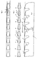
- eine Seitenansicht eines Ausschnittes eines Sägeblatts mit vier Zähnen der ersten Gruppe, die zunehmende Höhe und abnehmende Breite aufweisen, und mit vier Zähnen der zweiten Gruppe, die jeweils zwischen zwei Zähnen der ersten Gruppe angeordnet sind, die größte Breite und eine Höhe aufweisen, die gleich der Höhe des vorangegangenen Zahnes der ersten Gruppe ist;
- Fig. 2:
- eine zu
Figur 1 gehörende Draufsicht; - Fig. 3:
- eine ebenfalls zu
Figur 1 gehörende Draufsicht, bei der die Breite zu den einzelnen Zähnen vermaßt ist; - Fig. 4:
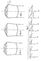
- ein Brustbild der Zähne der zweiten Gruppe;
- Fig. 5:
- ein Brustbild der Zähne der ersten Gruppe;
- Fig. 6:
- ein Brustbild der Kombination aus den Brustbildern der
Figuren 4 und 5 ; - Fig. 7:
- die Höhen der in der Kombination verwendeten Zähne;
- Fig. 8:
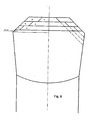
- in vergrößerter Darstellung das Brustbild der Kombination nach
Figur 6 mit bezifferten Zähnen; - Fig. 9:
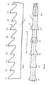
- eine Seitenansicht eines weiteren Ausschnittes eines Sägeblatts mit drei Zähnen der ersten Gruppe, die zunehmende Höhe und abnehmende Breite aufweisen, und mit drei Zähnen der zweiten Gruppe, die jeweils zwischen zwei Zähnen der ersten Gruppe angeordnet sind, die untereinander gleich ausgebildet sind und die größte Breite aufweisen; nicht gemäß Anspruch.
- Fig. 10:
- eine zu
Figur 9 gehörende Draufsicht im Ausschnitt. - Die als Ausführunsbeispiel gewählten Sägeblätter weisen einen Grundkörper 1 auf. Auf dem Grundkörper 1 sind ungeschränkte Zähne 2 angeordnet. Die Zähne 2 sind zu jeweils zwei Gruppen aus mindestens zwei Zähnen zusammengefaßt.
- Jeder Zahn 2 weist an seinem dem Grundkörper 1 abgewandten Ende einen Zahnrükken 21 auf. Auf der in Schneidrichtung X zugewandten Seite weist jeder Zahn 2 eine Zahnbrust 22 auf. Die Zahnbrust 22 ist unter einem Spanwinkel α zur Vertikalen angeordnet. Der Spanwinkel kann innerhalb einer Zahngruppe variieren. Er ist in einem Bereich angesiedelt, der von der Vertikalen entgegen dem Uhrzeigersinn wandert. Der Zahnrücken 21 eines jeden Zahns 2 ist unter einem Freiwinkel β zur Horizontalen des Sägeblatts angeordnet. Der Freiwinkel β ist immer größer als 0°.
Der Zahnrücken 21 und die Zahnbrust 22 eines jeden Zahns 2 sind unter einem Keilwinkel γ zueinander angeordnet, der in jedem Fall kleiner 90° ist. - Die Zähne 2 weisen einen Phasenwinkel δ auf. Der Phasenwinkel δ kann in einem Bereich zwischen 5° und 60° gewählt werden. Auch kann der Phasenwinkel δ innerhalb einer Zahngruppe von Zahn zu Zahn variieren.
- Bei der Ausführung nach
Figur 1 bis 8 weisen die zu der ersten Gruppe von Zähnen zusammengefaßten Zähne z1, z3, z5 und z7 eine von Zahn zu Zahn zunehmende Höhe h auf. Gleichzeitig nimmt die Breite b der zu der Gruppe zusammengefaßten Zähne z1, z3, z5 und z7 ab. Daraus ergibt sich, daß der niedrigste Zahn z1 der ersten Gruppe gleichzeitig der breiteste, der höchste Zahn z7 der schmalste Zahn ist. Die Zunahme der Höhe von Zahn zu Zahn beträgt mindestens 1/1000 mm, höchstens 5/100 mm. Die abnehmende Breite ist vorhanden, um einem folgenden Zahn im Schnittkanal vom vorschneidenden Zahn seitlich zu trennen. - Die zu der zweiten Gruppe von Zähnen zusammengefaßten Zähne z2, z4, z6 und z8 weisen eine von Zahn zu Zahn zunehmende Höhe h auf. Die Höhe eines Zahnes, z. B. z2, ist gleich der Höhe des vorangegangenen Zahnes z1 der ersten Gruppe. Die Breite b der Zähne der zweiten Gruppe ist gleich; die Zähne z2, z4, z6 und z8 haben übereinstimmend die größte Breite der Zähne des Sägebandes.
- Innerhalb der Zahnfolge beginnt es zunächst mit dem Zahn z1 aus der ersten Gruppe und dem Zahn z2 der zweiten Gruppe gleich dahinter. Dann kommen Zahn z3 aus der ersten Gruppe und z4 aus der zweiten Gruppe; danach aus der ersten Gruppe der Zahn z5. Bevor Zahn z5 wirkt, macht Zahn z4 aus der zweiten Gruppe den Schnittkanal wieder frei. Der Zahn z5 aus der ersten Gruppe hat dadurch weniger zu arbeiten. Nach z5 kommt z6, dann z7 der ersten Gruppe und schließlich z8 der zweiten Gruppe.
- Zusammengefaßt ist bei dieser Ausgestaltung zwischen jeden der Zähne der ersten Gruppe ein kurzer breiter Zahn der zweiten Gruppe gesetzt. Die Zähne der ersten Gruppe haben ansteigende Höhe nach hinten und nach hinten abnehmende Breite. Insgesamt gesehen hat das Sägeband nur ansteigende Höhen. Die Breite, die Phase, wird zwar immer länger, aber die Phase endet immer wieder auf der Kante. Die Phasen sind nur größer, weil der Zahn nach hinten länger herausragt. Im Ergebnis heißt dies aufsteigende Höhe und gleiche Breite. Dieses Ergebnis wird erzielt durch die Kombination der Zähne der ersten Gruppe mit den Zähnen der zweiten Gruppe.
- Bei dem anderen Ausführungsbeispiel -
Figuren 9 und 10 - nicht gemäß Anspruch. - sind die Zähne 2 der zweiten Gruppe, also die Zähne z2, untereinander gleich ausgebildet. Sie haben die größte Breite b und die kleinste Höhe h der Zähne des Sägebandes. Die Zähne der ersten Gruppe, also die Zähne z1, z3 und z5, haben eine von Zahn zu Zahn zunehmende Höhe h und abnehmende Breite b. - Die Zähne 2 sind zu zwei Gruppen von Zähnen aus jeweils mindestens zwei Zähnen zusammengefaßt. Die Gruppen von Zähnen wiederholen sich zyklisch auf dem Sägeband. Dabei ist es möglich, daß jeweils identische Gruppen von Zähnen aufeinander folgen. Es besteht darüber hinaus die Möglichkeit, daß die aufeinanderfolgenden Zahngruppen jeweils eine unterschiedliche Anzahl von Zähnen aufweisen. Die Gruppen von Zähnen sind miteinander verschachtelt. Die Teilung des Sägeblattes, also der Abstand der Zähne untereinander, kann konstant oder variabel gewählt werden.
Claims (1)
- Sägeblatt mit einem Grundkörper (1), auf dem ungeschränkte Zähne (2) mit Schneiden angeordnet sind, die symmetrisch zur Längsmittelebene des Grundkörpers (1) ausgebildet sind, wobei die Zähne (2) in sich wiederholenden Gruppen zu mindestens zwei Gruppen von Zähnen angeordnet sind, von denen die Zähne der ersten Gruppe aus mindestens zwei Zähnen bestehen und eine von Zahn zu Zahn zunehmende Höhe und gleichzeitig abnehmende Breite aufweisen, dadurch gekennzeichnet, dass die Zähne der zweiten Gruppe die Zähne mit der größten Breite darstellen, dass zwischen jeweils zwei Zähnen der ersten Gruppe ein Zahn der zweiten Gruppe angeordnet ist, und dass die Zähne (2) der zweiten Gruppe eine Höhe haben, die gleich der Höhe des vorangegangenen Zahnes der ersten Gruppe ist.
Applications Claiming Priority (1)
| Application Number | Priority Date | Filing Date | Title |
|---|---|---|---|
| PCT/DE1999/002587 WO2001012371A1 (de) | 1999-08-17 | 1999-08-17 | Sägeblatt mit gruppen von zähnen unterschiedlicher breiten oder höhen |
Publications (3)
| Publication Number | Publication Date |
|---|---|
| EP1204505A1 EP1204505A1 (de) | 2002-05-15 |
| EP1204505B1 EP1204505B1 (de) | 2003-04-23 |
| EP1204505B2 true EP1204505B2 (de) | 2013-07-31 |
Family
ID=6918845
Family Applications (1)
| Application Number | Title | Priority Date | Filing Date |
|---|---|---|---|
| EP99952434.1A Expired - Lifetime EP1204505B2 (de) | 1999-08-17 | 1999-08-17 | Sägeblatt mit gruppen von zähnen unterschiedlicher breiten oder höhen |
Country Status (5)
| Country | Link |
|---|---|
| EP (1) | EP1204505B2 (de) |
| JP (1) | JP2003507196A (de) |
| AT (1) | ATE238123T1 (de) |
| DE (1) | DE59905254D1 (de) |
| WO (1) | WO2001012371A1 (de) |
Families Citing this family (3)
| Publication number | Priority date | Publication date | Assignee | Title |
|---|---|---|---|---|
| DE20221854U1 (de) | 2002-11-18 | 2008-07-17 | Arntz Gmbh + Co. Kg | Sägeblatt |
| DE20316149U1 (de) * | 2003-10-18 | 2005-02-24 | Robert Bosch Gmbh | Stichsäge |
| JP7091483B2 (ja) * | 2019-06-27 | 2022-06-27 | 湖南泰嘉新材料科技股▲ふん▼有限公司 | 帯鋸刃 |
Citations (5)
| Publication number | Priority date | Publication date | Assignee | Title |
|---|---|---|---|---|
| DE2516137A1 (de) † | 1975-04-12 | 1976-10-21 | Ohler Fa Joh F | Kreissaegeblatt |
| US4011783A (en) † | 1976-01-22 | 1977-03-15 | Lear-Sigler, Inc. | Circular saw |
| DE3611063A1 (de) † | 1985-04-03 | 1986-10-16 | Amada Co. Ltd., Isehara, Kanagawa | Saegeblatt |
| EP0551104B1 (de) † | 1992-01-10 | 1996-02-07 | WIKUS-Sägenfabrik Wilhelm H. Kullmann | Sägeblatt |
| EP0610647B1 (de) † | 1993-01-13 | 1997-12-10 | WIKUS-Sägenfabrik Wilhelm H. Kullmann | Sägeblatt mit einem Grundkörper und ungeschränkten Zähnen |
Family Cites Families (2)
| Publication number | Priority date | Publication date | Assignee | Title |
|---|---|---|---|---|
| US3576200A (en) * | 1969-02-26 | 1971-04-27 | Heinemann Saw Corp | Circular saw |
| WO1998045076A1 (de) * | 1997-04-04 | 1998-10-15 | Handschuh & Scheider Gmbh | Sägeblatt |
-
1999
- 1999-08-17 AT AT99952434T patent/ATE238123T1/de active
- 1999-08-17 JP JP2001516701A patent/JP2003507196A/ja active Pending
- 1999-08-17 WO PCT/DE1999/002587 patent/WO2001012371A1/de not_active Ceased
- 1999-08-17 DE DE59905254T patent/DE59905254D1/de not_active Expired - Lifetime
- 1999-08-17 EP EP99952434.1A patent/EP1204505B2/de not_active Expired - Lifetime
Patent Citations (6)
| Publication number | Priority date | Publication date | Assignee | Title |
|---|---|---|---|---|
| DE2516137A1 (de) † | 1975-04-12 | 1976-10-21 | Ohler Fa Joh F | Kreissaegeblatt |
| US4011783A (en) † | 1976-01-22 | 1977-03-15 | Lear-Sigler, Inc. | Circular saw |
| DE3611063A1 (de) † | 1985-04-03 | 1986-10-16 | Amada Co. Ltd., Isehara, Kanagawa | Saegeblatt |
| EP0551104B1 (de) † | 1992-01-10 | 1996-02-07 | WIKUS-Sägenfabrik Wilhelm H. Kullmann | Sägeblatt |
| DE4200423C2 (de) † | 1992-01-10 | 1997-02-20 | Kullmann Wikus Saegenfab | Sägeblatt |
| EP0610647B1 (de) † | 1993-01-13 | 1997-12-10 | WIKUS-Sägenfabrik Wilhelm H. Kullmann | Sägeblatt mit einem Grundkörper und ungeschränkten Zähnen |
Also Published As
| Publication number | Publication date |
|---|---|
| ATE238123T1 (de) | 2003-05-15 |
| JP2003507196A (ja) | 2003-02-25 |
| EP1204505A1 (de) | 2002-05-15 |
| DE59905254D1 (de) | 2003-05-28 |
| EP1204505B1 (de) | 2003-04-23 |
| WO2001012371A1 (de) | 2001-02-22 |
Similar Documents
| Publication | Publication Date | Title |
|---|---|---|
| EP0551104B1 (de) | Sägeblatt | |
| EP0921884B1 (de) | Sägeblatt | |
| DE3300791C2 (de) | Sägeblatt | |
| DE3611063C2 (de) | ||
| DE19821525B4 (de) | Sägeblatt | |
| EP2277652B1 (de) | Sägeblatt mit Zähnen mit einem Spanumformelement | |
| EP1112797B1 (de) | Sägeblatt mit Grundkörper und ungeschränkten Zähnen | |
| EP0610647B1 (de) | Sägeblatt mit einem Grundkörper und ungeschränkten Zähnen | |
| DE2161233A1 (de) | Scheibenfräser, insbesondere Schlitz-, Nut- oder Formfräser | |
| EP1269923A2 (de) | Chirurgisches Sägeblatt | |
| DE3940552A1 (de) | Saegeblatt | |
| EP2570216B1 (de) | Sägeblatt mit Leistungszähnen und Oberflächenzähnen | |
| EP2060356A2 (de) | Sägeblatt mit einem Grundkörper und Zähnen mit Schneiden | |
| DE2311377A1 (de) | Spiralsaegeblatt | |
| EP3356073A1 (de) | Sägeblatt mit einem spanteilerzahn | |
| EP0038944B1 (de) | Sägeblatt | |
| DE10253711B4 (de) | Sägeblatt | |
| EP1204505B1 (de) | Sägeblatt mit gruppen von zähnen unterschiedlicher breiten oder höhen | |
| EP0009512B1 (de) | Sägeblatt zum Trennen von Holz und ähnlichen Werkstoffen | |
| EP1444067B1 (de) | Sägeblatt | |
| DE1030987B (de) | Saege, insbesondere Saegekette, mit hakenfoermig gestalteten Saegezaehnen | |
| DE69627673T2 (de) | Sägeblatt mit sich wiederholenden Zahngruppen | |
| DE3026980A1 (de) | Steinsaegeband zum saegen von gesteinsbloecken | |
| DE202012100736U1 (de) | Sägeblatt mit Öffnungen im Schaft |
Legal Events
| Date | Code | Title | Description |
|---|---|---|---|
| PUAI | Public reference made under article 153(3) epc to a published international application that has entered the european phase |
Free format text: ORIGINAL CODE: 0009012 |
|
| 17P | Request for examination filed |
Effective date: 20020207 |
|
| AK | Designated contracting states |
Kind code of ref document: A1 Designated state(s): AT BE CH CY DE DK ES FI FR GB GR IE IT LI LU MC NL PT SE |
|
| GRAH | Despatch of communication of intention to grant a patent |
Free format text: ORIGINAL CODE: EPIDOS IGRA |
|
| RTI1 | Title (correction) |
Free format text: SAW BLADE WITH GROUPS OF TEETH OF DIFFERENT WIDTHS OR HEIGHTS |
|
| GRAH | Despatch of communication of intention to grant a patent |
Free format text: ORIGINAL CODE: EPIDOS IGRA |
|
| GRAA | (expected) grant |
Free format text: ORIGINAL CODE: 0009210 |
|
| AK | Designated contracting states |
Designated state(s): AT BE CH CY DE DK ES FI FR GB GR IE IT LI LU MC NL PT SE |
|
| PG25 | Lapsed in a contracting state [announced via postgrant information from national office to epo] |
Ref country code: NL Free format text: LAPSE BECAUSE OF FAILURE TO SUBMIT A TRANSLATION OF THE DESCRIPTION OR TO PAY THE FEE WITHIN THE PRESCRIBED TIME-LIMIT Effective date: 20030423 Ref country code: IT Free format text: LAPSE BECAUSE OF FAILURE TO SUBMIT A TRANSLATION OF THE DESCRIPTION OR TO PAY THE FEE WITHIN THE PRESCRIBED TIME-LIMIT;WARNING: LAPSES OF ITALIAN PATENTS WITH EFFECTIVE DATE BEFORE 2007 MAY HAVE OCCURRED AT ANY TIME BEFORE 2007. THE CORRECT EFFECTIVE DATE MAY BE DIFFERENT FROM THE ONE RECORDED. Effective date: 20030423 Ref country code: IE Free format text: LAPSE BECAUSE OF FAILURE TO SUBMIT A TRANSLATION OF THE DESCRIPTION OR TO PAY THE FEE WITHIN THE PRESCRIBED TIME-LIMIT Effective date: 20030423 Ref country code: FI Free format text: LAPSE BECAUSE OF FAILURE TO SUBMIT A TRANSLATION OF THE DESCRIPTION OR TO PAY THE FEE WITHIN THE PRESCRIBED TIME-LIMIT Effective date: 20030423 |
|
| REG | Reference to a national code |
Ref country code: GB Ref legal event code: FG4D Free format text: NOT ENGLISH |
|
| REG | Reference to a national code |
Ref country code: CH Ref legal event code: EP |
|
| REF | Corresponds to: |
Ref document number: 59905254 Country of ref document: DE Date of ref document: 20030528 Kind code of ref document: P |
|
| REG | Reference to a national code |
Ref country code: IE Ref legal event code: FG4D Free format text: GERMAN |
|
| PG25 | Lapsed in a contracting state [announced via postgrant information from national office to epo] |
Ref country code: SE Free format text: LAPSE BECAUSE OF FAILURE TO SUBMIT A TRANSLATION OF THE DESCRIPTION OR TO PAY THE FEE WITHIN THE PRESCRIBED TIME-LIMIT Effective date: 20030723 Ref country code: PT Free format text: LAPSE BECAUSE OF FAILURE TO SUBMIT A TRANSLATION OF THE DESCRIPTION OR TO PAY THE FEE WITHIN THE PRESCRIBED TIME-LIMIT Effective date: 20030723 Ref country code: GR Free format text: LAPSE BECAUSE OF FAILURE TO SUBMIT A TRANSLATION OF THE DESCRIPTION OR TO PAY THE FEE WITHIN THE PRESCRIBED TIME-LIMIT Effective date: 20030723 Ref country code: DK Free format text: LAPSE BECAUSE OF FAILURE TO SUBMIT A TRANSLATION OF THE DESCRIPTION OR TO PAY THE FEE WITHIN THE PRESCRIBED TIME-LIMIT Effective date: 20030723 |
|
| PG25 | Lapsed in a contracting state [announced via postgrant information from national office to epo] |
Ref country code: LU Free format text: LAPSE BECAUSE OF NON-PAYMENT OF DUE FEES Effective date: 20030817 Ref country code: CY Free format text: LAPSE BECAUSE OF FAILURE TO SUBMIT A TRANSLATION OF THE DESCRIPTION OR TO PAY THE FEE WITHIN THE PRESCRIBED TIME-LIMIT Effective date: 20030817 |
|
| PG25 | Lapsed in a contracting state [announced via postgrant information from national office to epo] |
Ref country code: MC Free format text: LAPSE BECAUSE OF NON-PAYMENT OF DUE FEES Effective date: 20030831 Ref country code: LI Free format text: LAPSE BECAUSE OF NON-PAYMENT OF DUE FEES Effective date: 20030831 Ref country code: CH Free format text: LAPSE BECAUSE OF NON-PAYMENT OF DUE FEES Effective date: 20030831 Ref country code: BE Free format text: LAPSE BECAUSE OF NON-PAYMENT OF DUE FEES Effective date: 20030831 |
|
| GBT | Gb: translation of ep patent filed (gb section 77(6)(a)/1977) | ||
| NLV1 | Nl: lapsed or annulled due to failure to fulfill the requirements of art. 29p and 29m of the patents act | ||
| PG25 | Lapsed in a contracting state [announced via postgrant information from national office to epo] |
Ref country code: ES Free format text: LAPSE BECAUSE OF FAILURE TO SUBMIT A TRANSLATION OF THE DESCRIPTION OR TO PAY THE FEE WITHIN THE PRESCRIBED TIME-LIMIT Effective date: 20031030 |
|
| PLBQ | Unpublished change to opponent data |
Free format text: ORIGINAL CODE: EPIDOS OPPO |
|
| PLBI | Opposition filed |
Free format text: ORIGINAL CODE: 0009260 |
|
| REG | Reference to a national code |
Ref country code: IE Ref legal event code: FD4D Ref document number: 1204505E Country of ref document: IE |
|
| 26 | Opposition filed |
Opponent name: WIKUS-SAEGENFABRIK Effective date: 20031030 |
|
| PLAX | Notice of opposition and request to file observation + time limit sent |
Free format text: ORIGINAL CODE: EPIDOSNOBS2 |
|
| ET | Fr: translation filed | ||
| BERE | Be: lapsed |
Owner name: *HANDSCHUH & SCHEIDER G.M.B.H. Effective date: 20030831 |
|
| REG | Reference to a national code |
Ref country code: CH Ref legal event code: PL |
|
| RAP2 | Party data changed (patent owner data changed or rights of a patent transferred) |
Owner name: MHPS HANDSCHUH GMBH & CO. KG |
|
| PLAX | Notice of opposition and request to file observation + time limit sent |
Free format text: ORIGINAL CODE: EPIDOSNOBS2 |
|
| PLAF | Information modified related to communication of a notice of opposition and request to file observations + time limit |
Free format text: ORIGINAL CODE: EPIDOSCOBS2 |
|
| PLBB | Reply of patent proprietor to notice(s) of opposition received |
Free format text: ORIGINAL CODE: EPIDOSNOBS3 |
|
| APAH | Appeal reference modified |
Free format text: ORIGINAL CODE: EPIDOSCREFNO |
|
| APBM | Appeal reference recorded |
Free format text: ORIGINAL CODE: EPIDOSNREFNO |
|
| APBP | Date of receipt of notice of appeal recorded |
Free format text: ORIGINAL CODE: EPIDOSNNOA2O |
|
| APBU | Appeal procedure closed |
Free format text: ORIGINAL CODE: EPIDOSNNOA9O |
|
| APBC | Information on closure of appeal procedure deleted |
Free format text: ORIGINAL CODE: EPIDOSDNOA9O |
|
| APBU | Appeal procedure closed |
Free format text: ORIGINAL CODE: EPIDOSNNOA9O |
|
| PUAH | Patent maintained in amended form |
Free format text: ORIGINAL CODE: 0009272 |
|
| STAA | Information on the status of an ep patent application or granted ep patent |
Free format text: STATUS: PATENT MAINTAINED AS AMENDED |
|
| 27A | Patent maintained in amended form |
Effective date: 20130731 |
|
| AK | Designated contracting states |
Kind code of ref document: B2 Designated state(s): AT BE CH CY DE DK ES FI FR GB GR IE IT LI LU MC NL PT SE |
|
| REG | Reference to a national code |
Ref country code: DE Ref legal event code: R102 Ref document number: 59905254 Country of ref document: DE Effective date: 20130731 |
|
| REG | Reference to a national code |
Ref country code: FR Ref legal event code: PLFP Year of fee payment: 18 |
|
| PGFP | Annual fee paid to national office [announced via postgrant information from national office to epo] |
Ref country code: DE Payment date: 20160418 Year of fee payment: 18 Ref country code: GB Payment date: 20160824 Year of fee payment: 18 |
|
| PGFP | Annual fee paid to national office [announced via postgrant information from national office to epo] |
Ref country code: FR Payment date: 20160825 Year of fee payment: 18 Ref country code: AT Payment date: 20160822 Year of fee payment: 18 |
|
| REG | Reference to a national code |
Ref country code: DE Ref legal event code: R119 Ref document number: 59905254 Country of ref document: DE |
|
| REG | Reference to a national code |
Ref country code: AT Ref legal event code: MM01 Ref document number: 238123 Country of ref document: AT Kind code of ref document: T Effective date: 20170817 |
|
| GBPC | Gb: european patent ceased through non-payment of renewal fee |
Effective date: 20170817 |
|
| REG | Reference to a national code |
Ref country code: FR Ref legal event code: ST Effective date: 20180430 |
|
| PG25 | Lapsed in a contracting state [announced via postgrant information from national office to epo] |
Ref country code: AT Free format text: LAPSE BECAUSE OF NON-PAYMENT OF DUE FEES Effective date: 20170817 |
|
| PG25 | Lapsed in a contracting state [announced via postgrant information from national office to epo] |
Ref country code: GB Free format text: LAPSE BECAUSE OF NON-PAYMENT OF DUE FEES Effective date: 20170817 Ref country code: DE Free format text: LAPSE BECAUSE OF NON-PAYMENT OF DUE FEES Effective date: 20180301 |
|
| PG25 | Lapsed in a contracting state [announced via postgrant information from national office to epo] |
Ref country code: FR Free format text: LAPSE BECAUSE OF NON-PAYMENT OF DUE FEES Effective date: 20170831 |