EP1204526B1 - Vorrichtung zur herstellung von kunststoffbehältern mittels streckblasformen unter verwendung eines explosiven blasmediums - Google Patents
Vorrichtung zur herstellung von kunststoffbehältern mittels streckblasformen unter verwendung eines explosiven blasmediums Download PDFInfo
- Publication number
- EP1204526B1 EP1204526B1 EP00956174A EP00956174A EP1204526B1 EP 1204526 B1 EP1204526 B1 EP 1204526B1 EP 00956174 A EP00956174 A EP 00956174A EP 00956174 A EP00956174 A EP 00956174A EP 1204526 B1 EP1204526 B1 EP 1204526B1
- Authority
- EP
- European Patent Office
- Prior art keywords
- container
- receiving portion
- hollow
- stretching
- stretching die
- Prior art date
- Legal status (The legal status is an assumption and is not a legal conclusion. Google has not performed a legal analysis and makes no representation as to the accuracy of the status listed.)
- Expired - Lifetime
Links
- 238000007664 blowing Methods 0.000 title claims abstract description 16
- 239000002360 explosive Substances 0.000 title claims abstract description 16
- 239000004033 plastic Substances 0.000 title claims abstract description 16
- 229920003023 plastic Polymers 0.000 title claims abstract description 16
- 238000004519 manufacturing process Methods 0.000 title claims abstract description 13
- 238000000071 blow moulding Methods 0.000 title description 3
- 239000000203 mixture Substances 0.000 claims abstract description 38
- 239000000463 material Substances 0.000 claims abstract description 7
- 238000007789 sealing Methods 0.000 claims description 58
- 229910000831 Steel Inorganic materials 0.000 claims description 19
- 239000010959 steel Substances 0.000 claims description 19
- 238000001816 cooling Methods 0.000 claims description 7
- 238000010438 heat treatment Methods 0.000 claims description 5
- 230000009969 flowable effect Effects 0.000 claims 5
- 239000007789 gas Substances 0.000 description 58
- 238000004880 explosion Methods 0.000 description 31
- 239000012530 fluid Substances 0.000 description 26
- 239000003795 chemical substances by application Substances 0.000 description 25
- 238000000034 method Methods 0.000 description 19
- XKRFYHLGVUSROY-UHFFFAOYSA-N Argon Chemical compound [Ar] XKRFYHLGVUSROY-UHFFFAOYSA-N 0.000 description 18
- 239000007795 chemical reaction product Substances 0.000 description 15
- 239000001257 hydrogen Substances 0.000 description 11
- 229910052739 hydrogen Inorganic materials 0.000 description 11
- 230000008569 process Effects 0.000 description 11
- QVGXLLKOCUKJST-UHFFFAOYSA-N atomic oxygen Chemical compound [O] QVGXLLKOCUKJST-UHFFFAOYSA-N 0.000 description 10
- 238000002485 combustion reaction Methods 0.000 description 10
- 239000001301 oxygen Substances 0.000 description 10
- 229910052760 oxygen Inorganic materials 0.000 description 10
- UFHFLCQGNIYNRP-UHFFFAOYSA-N Hydrogen Chemical compound [H][H] UFHFLCQGNIYNRP-UHFFFAOYSA-N 0.000 description 9
- 229910052786 argon Inorganic materials 0.000 description 9
- 238000009826 distribution Methods 0.000 description 9
- 229920000139 polyethylene terephthalate Polymers 0.000 description 9
- 239000005020 polyethylene terephthalate Substances 0.000 description 9
- XLYOFNOQVPJJNP-UHFFFAOYSA-N water Substances O XLYOFNOQVPJJNP-UHFFFAOYSA-N 0.000 description 9
- 239000011261 inert gas Substances 0.000 description 7
- 230000013011 mating Effects 0.000 description 7
- 238000002156 mixing Methods 0.000 description 7
- 238000000465 moulding Methods 0.000 description 6
- 238000007493 shaping process Methods 0.000 description 6
- 230000001954 sterilising effect Effects 0.000 description 6
- 230000008901 benefit Effects 0.000 description 5
- 238000006243 chemical reaction Methods 0.000 description 5
- 230000002349 favourable effect Effects 0.000 description 5
- 238000004659 sterilization and disinfection Methods 0.000 description 5
- 238000011049 filling Methods 0.000 description 4
- 238000010926 purge Methods 0.000 description 4
- 239000000919 ceramic Substances 0.000 description 3
- 238000010276 construction Methods 0.000 description 3
- 230000006735 deficit Effects 0.000 description 3
- 238000013461 design Methods 0.000 description 3
- 150000002431 hydrogen Chemical class 0.000 description 3
- 238000007639 printing Methods 0.000 description 3
- 239000007787 solid Substances 0.000 description 3
- 230000003319 supportive effect Effects 0.000 description 3
- 238000010924 continuous production Methods 0.000 description 2
- 239000003480 eluent Substances 0.000 description 2
- 230000004907 flux Effects 0.000 description 2
- VNWKTOKETHGBQD-UHFFFAOYSA-N methane Chemical compound C VNWKTOKETHGBQD-UHFFFAOYSA-N 0.000 description 2
- 230000001960 triggered effect Effects 0.000 description 2
- 241001463014 Chazara briseis Species 0.000 description 1
- MYMOFIZGZYHOMD-UHFFFAOYSA-N Dioxygen Chemical compound O=O MYMOFIZGZYHOMD-UHFFFAOYSA-N 0.000 description 1
- 206010040925 Skin striae Diseases 0.000 description 1
- 208000031439 Striae Distensae Diseases 0.000 description 1
- 238000010521 absorption reaction Methods 0.000 description 1
- 230000009471 action Effects 0.000 description 1
- 230000009286 beneficial effect Effects 0.000 description 1
- 230000015572 biosynthetic process Effects 0.000 description 1
- 238000005422 blasting Methods 0.000 description 1
- 230000003197 catalytic effect Effects 0.000 description 1
- 230000008859 change Effects 0.000 description 1
- 238000001311 chemical methods and process Methods 0.000 description 1
- 239000004020 conductor Substances 0.000 description 1
- 238000007796 conventional method Methods 0.000 description 1
- 238000010586 diagram Methods 0.000 description 1
- 229910001882 dioxygen Inorganic materials 0.000 description 1
- 238000005868 electrolysis reaction Methods 0.000 description 1
- 238000011010 flushing procedure Methods 0.000 description 1
- 230000001976 improved effect Effects 0.000 description 1
- 238000002347 injection Methods 0.000 description 1
- 239000007924 injection Substances 0.000 description 1
- 238000009434 installation Methods 0.000 description 1
- 230000001788 irregular Effects 0.000 description 1
- 239000007788 liquid Substances 0.000 description 1
- 238000002844 melting Methods 0.000 description 1
- 230000008018 melting Effects 0.000 description 1
- 239000002184 metal Substances 0.000 description 1
- 239000007800 oxidant agent Substances 0.000 description 1
- 239000004014 plasticizer Substances 0.000 description 1
- -1 polyethylene terephthalate Polymers 0.000 description 1
- 238000002360 preparation method Methods 0.000 description 1
- 238000004886 process control Methods 0.000 description 1
- 238000012545 processing Methods 0.000 description 1
- 230000005855 radiation Effects 0.000 description 1
- 238000011084 recovery Methods 0.000 description 1
- 239000002689 soil Substances 0.000 description 1
- 239000000243 solution Substances 0.000 description 1
- 229910001220 stainless steel Inorganic materials 0.000 description 1
- 239000010935 stainless steel Substances 0.000 description 1
- 230000003068 static effect Effects 0.000 description 1
- 238000012859 sterile filling Methods 0.000 description 1
- 238000003860 storage Methods 0.000 description 1
- 239000008030 superplasticizer Substances 0.000 description 1
- 230000008093 supporting effect Effects 0.000 description 1
- 238000013022 venting Methods 0.000 description 1
- 230000000007 visual effect Effects 0.000 description 1
Images





Classifications
-
- B—PERFORMING OPERATIONS; TRANSPORTING
- B29—WORKING OF PLASTICS; WORKING OF SUBSTANCES IN A PLASTIC STATE IN GENERAL
- B29C—SHAPING OR JOINING OF PLASTICS; SHAPING OF MATERIAL IN A PLASTIC STATE, NOT OTHERWISE PROVIDED FOR; AFTER-TREATMENT OF THE SHAPED PRODUCTS, e.g. REPAIRING
- B29C49/00—Blow-moulding, i.e. blowing a preform or parison to a desired shape within a mould; Apparatus therefor
- B29C49/08—Biaxial stretching during blow-moulding
- B29C49/10—Biaxial stretching during blow-moulding using mechanical means for prestretching
- B29C49/12—Stretching rods
-
- B—PERFORMING OPERATIONS; TRANSPORTING
- B29—WORKING OF PLASTICS; WORKING OF SUBSTANCES IN A PLASTIC STATE IN GENERAL
- B29C—SHAPING OR JOINING OF PLASTICS; SHAPING OF MATERIAL IN A PLASTIC STATE, NOT OTHERWISE PROVIDED FOR; AFTER-TREATMENT OF THE SHAPED PRODUCTS, e.g. REPAIRING
- B29C49/00—Blow-moulding, i.e. blowing a preform or parison to a desired shape within a mould; Apparatus therefor
- B29C49/42—Component parts, details or accessories; Auxiliary operations
- B29C49/46—Component parts, details or accessories; Auxiliary operations characterised by using particular environment or blow fluids other than air
-
- B—PERFORMING OPERATIONS; TRANSPORTING
- B29—WORKING OF PLASTICS; WORKING OF SUBSTANCES IN A PLASTIC STATE IN GENERAL
- B29C—SHAPING OR JOINING OF PLASTICS; SHAPING OF MATERIAL IN A PLASTIC STATE, NOT OTHERWISE PROVIDED FOR; AFTER-TREATMENT OF THE SHAPED PRODUCTS, e.g. REPAIRING
- B29C49/00—Blow-moulding, i.e. blowing a preform or parison to a desired shape within a mould; Apparatus therefor
- B29C49/42—Component parts, details or accessories; Auxiliary operations
- B29C2049/4294—Sealing means
-
- B—PERFORMING OPERATIONS; TRANSPORTING
- B29—WORKING OF PLASTICS; WORKING OF SUBSTANCES IN A PLASTIC STATE IN GENERAL
- B29C—SHAPING OR JOINING OF PLASTICS; SHAPING OF MATERIAL IN A PLASTIC STATE, NOT OTHERWISE PROVIDED FOR; AFTER-TREATMENT OF THE SHAPED PRODUCTS, e.g. REPAIRING
- B29C49/00—Blow-moulding, i.e. blowing a preform or parison to a desired shape within a mould; Apparatus therefor
- B29C49/42—Component parts, details or accessories; Auxiliary operations
- B29C49/46—Component parts, details or accessories; Auxiliary operations characterised by using particular environment or blow fluids other than air
- B29C2049/4602—Blowing fluids
- B29C2049/4647—Blowing fluids created by an explosive gas mixture
-
- B—PERFORMING OPERATIONS; TRANSPORTING
- B29—WORKING OF PLASTICS; WORKING OF SUBSTANCES IN A PLASTIC STATE IN GENERAL
- B29C—SHAPING OR JOINING OF PLASTICS; SHAPING OF MATERIAL IN A PLASTIC STATE, NOT OTHERWISE PROVIDED FOR; AFTER-TREATMENT OF THE SHAPED PRODUCTS, e.g. REPAIRING
- B29C2949/00—Indexing scheme relating to blow-moulding
- B29C2949/07—Preforms or parisons characterised by their configuration
- B29C2949/0715—Preforms or parisons characterised by their configuration the preform having one end closed
-
- B—PERFORMING OPERATIONS; TRANSPORTING
- B29—WORKING OF PLASTICS; WORKING OF SUBSTANCES IN A PLASTIC STATE IN GENERAL
- B29C—SHAPING OR JOINING OF PLASTICS; SHAPING OF MATERIAL IN A PLASTIC STATE, NOT OTHERWISE PROVIDED FOR; AFTER-TREATMENT OF THE SHAPED PRODUCTS, e.g. REPAIRING
- B29C49/00—Blow-moulding, i.e. blowing a preform or parison to a desired shape within a mould; Apparatus therefor
- B29C49/02—Combined blow-moulding and manufacture of the preform or the parison
- B29C49/06—Injection blow-moulding
-
- B—PERFORMING OPERATIONS; TRANSPORTING
- B29—WORKING OF PLASTICS; WORKING OF SUBSTANCES IN A PLASTIC STATE IN GENERAL
- B29K—INDEXING SCHEME ASSOCIATED WITH SUBCLASSES B29B, B29C OR B29D, RELATING TO MOULDING MATERIALS OR TO MATERIALS FOR MOULDS, REINFORCEMENTS, FILLERS OR PREFORMED PARTS, e.g. INSERTS
- B29K2067/00—Use of polyesters or derivatives thereof, as moulding material
-
- B—PERFORMING OPERATIONS; TRANSPORTING
- B29—WORKING OF PLASTICS; WORKING OF SUBSTANCES IN A PLASTIC STATE IN GENERAL
- B29L—INDEXING SCHEME ASSOCIATED WITH SUBCLASS B29C, RELATING TO PARTICULAR ARTICLES
- B29L2031/00—Other particular articles
- B29L2031/712—Containers; Packaging elements or accessories, Packages
- B29L2031/7158—Bottles
Definitions
- the invention relates to an apparatus for producing containers from a stretch-blown deformable plastic with a shape whose interior corresponds to the finished container, which is held at its open end by a receptacle, wherein with a metering unit connected lines are provided on the receptacle, a movable stretching punch axially guided by the receptacle and an ignition device is arranged to an explosive Igniting gas mixture within the container, and wherein heating and cooling devices provided are.
- WO98 / 06559 discloses a device of previously described type for the production of containers made of plastic, for example of polyethylene terephthalate (PET) bottles. These PET bottles are made by it made, that first a preform to a suitable temperature for the stretch-blowing is heated from about 100 - 120 ° C. This preform is in one of the shape of the container corresponding Tool mold introduced, and it is a stretching pressure of at least 2 bar, usually 5 - 10 bar, generated. By means of an axially and generally vertically movable Streckstkovs the preform is stretched axially. Thereupon, in the preform, a blowing pressure generated, which is in the range of 40 bar.
- PET polyethylene terephthalate
- the wall of the preform to the Inner wall of the mold pressed and thereby formed the container.
- an explosive gas mixture into the preform for example a mixture of Oxygen gas and an inert gas is generated
- the blowing pressure is created by igniting the explosive Gas mixture, and this blowing pressure presses the wall of the intermediate molding or the partial preformed container entirely to the inner wall of the mold.
- the ignition of the explosive gas mixture is effected by a spark generator or a radiation, and the explosive gas mixture is a mixture of an oxidizing agent and an oxidizable component such as hydrogen, methane or the like.
- the invention has the object, a device of the aforementioned To create a kind of plastic container with a better appearance, For example, with largely clear wall, without much extra effort to produce are.
- the recording at her the container the end facing away from the fluid-tight with a manifold block is engageable by which the draw punch is guided in the axial extension of the receptacle movable and to which at least one fluid connection is attached, that the at least one Fluids connection for sealing the device-side interior is closed and that the ignition device is mounted in the device-side interior.
- the manifold block in sealing Engaged and disengaged from the manifold block at the other stage.
- Stretching is the stretching punch through the manifold block and thus also axially through the recording passed through movable.
- a device-side interior through the connected parts of the manifold, receptacle and seated one another Container formed.
- the flow agent is at least a fluid connection in the manifold block and through this into the receptacle and the container guided.
- the device-side interior through the same device parts formed, but in addition to flow agent also through the draw punch the interior the container can be supplied.
- the device-side interior is only through the container and the receptacle disposed thereon is formed when, for example, the manifold block of the recording separated and the recording is closed.
- Axial through the picture is the Outstretched, and this may contain a supply line. He can also be massive be executed.
- Each of the various device-side interiors (depending on the embodiment) is but in the area of the one fluid connection or the plurality of fluid connections can be closed. Only in a closed device-side interior causes by the There also arranged ignition caused explosion the desired parameters short term high pressure and higher temperature. It is understood that these interiors can be reopened after completion of the manufacturing process.
- the advantage of the limited device-side interior is its small volume.
- the volume in the container to be produced is less critical.
- the device side Volume involved in enclosing the blast space is so small by the measures of the invention in relation to the known device, that reaction products, when using oxyhydrogen, for example, water, in considerably less Quantity remains. It has been found that the haze of the container walls thereby emerged that formed when using oxyhydrogen gas in droplet form with considerable Kinetic energy is thrown from the inside to the walls and there surface changes which ultimately leads to cloudiness.
- the invention is advantageously further configured in that the receptacle is hollow and on her The end facing away from the container has a sealing surface through which the draw punch in axial extension of the receptacle is movably passed.
- the recording is preferred hollow, so that the stretching punch through the entire, elongated recording of her an end can be axially moved to its opposite end. nevertheless the receptacle with the distributor block is fluid-tight connectable by the sealing surface, the extends around the space for the stretching punch around and is therefore annular.
- the closing means for sealing the Device-side interior is a check valve.
- Check valves are in very different Embodiments known per se. At each port of the manifold block can a check valve may be mounted when the embodiment is selected, also softer the distributor block belongs to the device which specifies the device-side interior. Another embodiment of check valve may also additionally or alternatively on Stretching temple be provided, possibly even in the stretching die, as in the following a preferred embodiment is described.
- the device-side interior is at a favorable embodiment formed by the container to be produced and the receptacle, For example, if this entity is separable from the manifold block.
- the stretching star is designed hollow and with at least one outlet opening arranged at a stretching tip, at least one Fluid inlet and is provided with at least one of these connecting inner channel and if preferably in the region of the outlet opening a check valve is mounted.
- the check valve in the Stretching stamp and thereby in the area of the outlet opening.
- Stretching dies for stretch-blow molding are known per se. The preheated preform is made with the help of the respective stretching punch stretched by its draw tip engaging the bottom of the preform occurs and pushes it.
- an inner channel to be arranged in the longitudinal direction of the stretching punch so that from its feed side end from the fluid inlet, the flow agent on the opposite side towards the Stretched tip can be pressed and pushed out of the outlet opening.
- one can at least one gas through the inner channel in the hollow drafting die into the space within the container to be produced because the fluid brought directly into the volume of the container at the outlet opening next to the drawing tip can be.
- a Ignition device within the hollow stretching punch on the outlet opening facing Side of the check valve attached and preferably over in the hollow drafting die extending cables or tracks is electrically connected to a control unit.
- the ignition of the explosive flux mixture can in such a structure of the hollow stretching punch take place almost in the center of the container to be produced. Further outside the container located device parts can then be decoupled or closed depending on the process become.
- the actuation of the ignition device via the cable or the conductor also succeeds advantageous by the hollow configuration of the stretching punch.
- the attachment of the check valve does not disturb, but it is preferably selected so that the entire inner channel in the hollow draw punch is separable from the explosion chamber by the check valve, namely when closing the check valve.
- the hollow stretch marks can be practically from a Produce stainless steel tube, but its stretch tip with a exchangeable and thus adaptable to the properties of each preform to be molded Cap is provided because these in the course of the process, the preheated preform under the action of his soil stretches.
- the flow agent outlet attached, preferably in the end region of the steel tube, namely where the draw tip with the Steel tube is connected by a screw or other connecting means.
- the eluent As far as possible At the top of the stretching tip is the eluent. He has hole structure. That means, that at least one hole in the outer wall of the tube is arranged such that the through the inner channel of the hollow drafting stamp flowing gases or other flow agents through this Hole or a corresponding number of holes can escape from the steel pipe. It it is also possible that the fluid outlet is another arrangement of regular or irregular distributed holes may have provided outlet. Under hole structure you can also understand a porous body of sintered metal, ceramic or the like, which then can serve as kickback protection at the same time.
- a preferred embodiment of the invention uses a hollow stretching punch with a Check valve, which is also located in the region of the draw tip, but in a certain distance, which for the absorption of the flow agent on the one hand and the Igniter on the other hand is used.
- the check valve in this embodiment has a valve body, which are moved against a sealing seat inside the steel tube so can, that thereby the check valve is closed. If such a drawing punch with strong vertical component, preferably entirely vertical, in the device according to the invention arranged, then exerts the valve body by its weight a kind of resilient bias down against the sealing seat, so that without flowing out of the inner channel As a result of its weight, the flow agent of the valve body always falls onto the sealing seat and so that the check valve closes.
- the closing of the check valve can also be achieved by the installation of a spring, in particular is necessary in non-vertical arrangement of the stretch temple.
- the ignition takes place anyway in the device-side interior, i. in the upper remaining space of the steel pipe next to the flow agent exit and outside the draw punch in the volume of the container, so that the increased by the explosion gas pressure in addition the valve body against the sealing seat press and the check valve closes.
- the valve body may preferably carry swirling means. This achieves a better one Turbulence of the fluid mixture when exiting the draw punch. For example one can see the movable valve body with spiraling on its outer surface Provided flow medium guide channels. Alternatively one can also exit holes diagonally in drill the draw punch so as to give the leaking flux a tangential velocity component to give.
- the cap-shaped stretch tip can be made of different materials, wherein made of solid plastic, made of a plastic-coated steel cap or even made of Ceramics can exist.
- a device has already been operated and measured, in which the stretching tip is made of steel. The reason to use steel instead of plastic and to investigate is excessive heating and thus impairment of the To avoid outer surface of the stretch tip in continuous operation.
- the recording perpendicular to its longitudinal central axis is movably driven.
- a large part of the device side Interior namely the space in the hollow receptacle, after each stretching and Blowing process, i. especially after each combustion, of the otherwise stationary device,
- the distributor block with the hollow piston to be removed separately the reaction products adhering to the walls.
- the device-side interior the most may be subject to reaction products, then limited to the space in the hollow die and in the distribution block.
- a preferred embodiment of the invention is characterized in that the Extended shot at the end remote from the manifold block to form a service room is in soft preferably a centering is used.
- the produced in each case Container has in case of a PET bottle at one longitudinal end of the filling or pouring opening in Shape of a federal government with external thread. In the known device surrounds the recording this open end of the container. Also according to the invention one holds the container to be produced most convenient at its open end, which is preferably in the form of a covenant with external thread present.
- the filling of a sterilized container is carried out by this filling or pouring opening, which can also be commonly referred to as a closure.
- a centering is used in this extended service room, because then both the preform and the subsequent container in the recording center well and let it rest.
- the centering is an additional part, which the service room partially filled, the contact of the sterilizing gases during and after combustion However, this does not hinder or impair, especially since an edge flange additionally for a Holder ensures.
- a relatively movable to this axially movable driven hollow piston is provided at its outer, the receiving end facing a matching to the receptacle, annular mating surface having.
- the Connecting the receptacle to the manifold block with the sealing surface of the receptacle in sealing Intervention occurs.
- the movement of the hollow piston is reversed, the sealing surface is disengaged from the mating surface, and then the Shooting shifted in the manner described above perpendicular to its longitudinal axis direction become.
- This shift transport takes place each time after a blow-sterilization process the step-by-step manufacturing process.
- According to the invention can also be in the distributor block for guiding the stretching punch a sealing bushing to escape attach to the hollow piston. With this succeeds the movement of the stretching punch in the axial direction through the manifold block, the hollow piston, the downstream recording and in the Container out or out of these parts, although the device-side interior gas-tight remains completed.
- At least one with the metering unit connected supply and a discharge line is connected to the manifold block.
- the discharge line serves to remove the reaction products, for example the Vebrennungsgase and optionally liquid residues.
- the supply line is connected to the dosing unit, which in a preferred Embodiment will be described in more detail.
- pressure sensors and temperature gauges at various locations may be arranged in the device, but preferably in the region of the distributor block also in the hollow stretch temple.
- the igniter on different physical principles can be based.
- the ignition of the media mixture takes place in the simplest case electrically over a spark gap, which consists for example of a spark plug, on the draw punch or can be attached to the distributor; or by static discharge.
- Ignition methods for example by irradiation of electromagnetic energy, such as in Shape of a laser, high-frequency or microwave pulse or with the help of a catalytic Process.
- Another favorable embodiment of a dosing unit sees the mixing of different Melting agent immediately before the drawing punch with direct subsequent introduction into the preform in front. This represents a good compromise, especially in terms of safety between the preparation of the mixture in a separate, explosion-proof pressure vessel and the dosing unit described above, in which by means of dosing individual Flow agents and / or fluid mixtures are supplied to the device-side interior.
- a practical embodiment according to the invention is further characterized in that in each of the supply and discharge lines connected to the manifold block has a check valve is connected and the ignition device is mounted in the manifold block.
- the Stretching stamps then surround the space in the distribution block, the space between stretch stamp and hollow piston and the between the punch and recording with distance. This distance means an annulus, which can be regarded as a flow agent channel and interpreted accordingly can. If the design is large, larger amounts of fluid can be pumped into the container and vice versa.
- the hollow piston at its recording facing the end of an annular sealing seat, and the drawstring bears on his in the container to be manufactured movable end for engagement with the sealing seat a perpendicular to its longitudinal axis radial extension.
- This can be spherical, conical, ring or have the same.
- the draw punch is massive in this embodiment and may be smaller in size Diameter be configured with the result that a larger flow channel for the Plasticizer is present outside of the stretching punch. This favors a fast, short-term Manufacturing process.
- the room intended for the explosion will be moved out the stretching punch and thus driving the extension into the sealing seat without the need closed further check valves, in which case only the ignition in the area the recording must be arranged.
- the cooling devices mentioned in the introduction for this purpose used to cool the draw punch separately.
- This can namely in the step by step continuous process already after several steps a temperature of 100 ° C or get higher, so that the materials of the device subjected to high stress become. Therefore, it is appropriate to increase the temperature of the movable stretching punch limit, and this succeeds despite the repeated explosions well by providing appropriate Cooling devices.
- the inner channel of the hollow stretching punch has been described above as a feed line, However, it is understood that the mixture supply via the manifold block and the derivative the reaction products can then be carried out according to the stretching punch.
- Figure 1 shows aborted on the top right one produced by the stretch-blown process Container 1 made of plastic, for example PET. While the finished molded and out of the tool demolded container is denoted by 1 is already partially by stretching and blowing preformed container in the following drawings with 1 '.
- Made is the Container 1 from a designated preform 2. From the entire manufacturing unit are shown only the parts important to the invention, while known per se parts of the tool are omitted, such as the shape whose interior corresponds to the finished container 1. It lacks in the illustrations, the brackets and rails for the transport of Workpieces according to arrow 3 in the treatment station and out of this. Shown is the but Recording 4, which is extended at the top to form a service room 5 above, in which a centering 6 is used.
- the container 1 to be produced is shown here as a PET bottle, with its open end. 7 arranged upside down and supported in the centering 6 and sealing in the recording 4 is held.
- a generally denoted by 11 Used stretch die which is guided axially movable through the receptacle 4.
- an ignition device 12 is arranged at one point, to ignite an explosive gas mixture within the container 1 '.
- Heating and cooling equipment, also the cooling means for the stretching punch 11, are for the sake of simplicity and Enlarged clarity of the drawings have been omitted.
- longitudinal central axis 13 extends also the stretching punch 11 in the vertical, with which the longitudinal central axis thirteenth to think coincidentally.
- This longitudinal central axis also runs centrally through the receptacle 4 and the preform 2 and the later intermediate molded container 1 'and the finished container 1. If the respective receptacle 4 is movable in the direction transverse to the longitudinal central axis 13, in order to transport the preforms 2 or container 1, this transport direction runs according to arrow 3 in the horizontal direction, while the longitudinal central axis 13 is vertical.
- the receptacle 4 is at its the container 1 and the preform 2, respectively mounted above is opposite end, i. below, fluid-tight with a manifold block 14 into engagement brought.
- This distributor block 14 is stationary and has a continuous vertical bore 15 in this sits down a sealing passage 16 through which the draw punch concentric and sealingly guided from the outside into the manifold block 14 and oscillating up and down is movable.
- At a distance from the Inner walls of the hollow piston 17 extends the opposite to the described parts movable Stretching Temple 11, the axial in alignment with the inclusion in the latter and in the latter of this held preform 2 or container 1 can penetrate.
- the hollow piston 17 has at its upper, namely the outer end 18, which of the recording 4, a matching to the latter annular sealing surface 18.
- the hollow recording 4 has at its end facing away from the container 1 and the preform 2 (below) a annular sealing surface 19. This fits to the mating surface 18 of the hollow piston 17 in such that upon movement of the hollow piston 17 from the position shown in Figure 1 moves up to the receptacle 4 to the mating surface 18 in the sealing surface 19 into it and ensures a proper, fluid-tight connection.
- the receptacle 4 with the distribution block 14 in fluid-tight engagement can be brought.
- a Hole 20 which is one of the fluid agent ports, passing over the stationary manifold block 14 are connected.
- a fluid interface is the access 21 to the then hollow extension punch 11; or in another embodiment are Ff dirtystoffan say designated 9 or 10 on the manifold block.
- At every fluid connection are for closing and sealing the device-side interior 22 check valves 23 attached. These can vary depending on the embodiment have, as partially explained below.
- the device-side interior 22 is that space in the tool and in the preform 2 and the container 1, in which the Explosion of the gas mixture takes place.
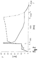
- time t 1 and t 2 are the internal pressure in the range of about 5 - 10 bar (pressure stretching) is held, so that the warm preform 2 is stretched and thereby also increases its diameter. So far, at time t 2 . the internal pressure of the non-explosive gases increased to a good 30 bar and kept until the time t 5 , whereby the preform 2 and the intermediate molded container 1 'is pressed completely against the mold and thereby the final shape of the container to be produced 1, for example the PET Bottle, receives. Then it is deaerated, the mold has been cooled in the meantime, the finished container was removed after the time t 7 of the mold.
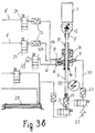
- the distributor block 14 shown on the right in FIG. 3b is used in the embodiment shown here supplied via the allocation 10'a or the Zulelung 10'b a gas mixture.
- This can about the respective check valve 23 and the designated respectively 24 valve via line 8 'or the line 8 "is made by a mixing and pressure cylinder 25 ( Figure 3a) Motor M driven and can mix 24 different gases depending on the position of the valves and feed through the line 10'a and / or 10'b of the further supply line 10 '.
- the gas container 26 contains a mixture of argon and oxygen (alternatively, in another embodiment, for example, air).
- the gas container 27 contains argon.
- About the mixing and printing cylinder 25, for example, a volume of 2 liters may be desired oxygen with a more or less large Part argon mixed and then fed to the feed line 8.
- the required hydrogen for example, continuously generate in each required small amounts in parallel in an electrolysis unit.
- This purge gas is in this embodiment Compressed air and serves to express water and gas residues from the system after the explosion.
- the jagged arrow drawn in a circle is the symbol for the generation of high voltage 32.
- the high voltage then leads to the ignition device located further up 12 to ignite the explosion.
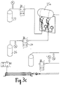
- FIGS. 3c and 3d describe a second, different embodiment of a dosing unit.
- the Dosing unit according to FIGS. 3c and 3d is very similar to that according to FIGS. 3a and 3b. why the same parts are to be understood by the same terms and reference numbers.
- Different is the pressure tank shown in Figure 3c 25a, of which only a supply line 8 'on the Valve 24 to the check valve 23 and from there as a supply line 10 a to the distributor 14 leads.
- the first embodiment according to FIGS. 3 a and 3 b can be used to achieve the embodiment be modified according to the figures 3c and 3d so that at preform pressures below 10 bar the Mixing and pressure cylinder 25 with its supply and discharge lines through the aforementioned pressure tank 25a is replaced.
- the gases are mixed, for example, from the gas containers 26th (Argon and oxygen) and 27 (argon) coming and led to the pressure tank 25 a gases. From this pressure tank 25a then only leads a supply line 8 'to the manifold block 14, as in Figure 3d is shown.
- the mixing and printing cylinder 25 of Figure 3a can in the second Embodiment of Figure 3c oxygen as desired with a more or less large Argon mixed in the pressure cylinder 25 a and then the distributor via the supply line 10'a be supplied.
- FIGS. 4 and 5 the upper or container-side end of the hollow-shaped stretching punch is shown 11 is shown.
- a plastic stretch lace 33 which may be made of steel or ceramic in other embodiments.
- the Plastic shown here is chosen so that the stretching of the container 1 'inserted tip is not overheated.
- the stretch tip 33 is bolted to the steel tube 34 via the holder 35.
- holes 20 in the steel pipe 34 which serve as a flow agent outlet in hole structure.
- the flow agent is from the elongated, device-side interior 22 of the hollow Stretch temple 11 can escape through the holes 20.
- the device-side interior 22 is in this embodiment, an elongated inner channel, which is parallel to the longitudinal central axis 13 extends from the check valve 23 to the height of the holes 20.
- the ignition device 12 has in the illustration of Figures 4 and 5, a spark plug, the is also parallel to the longitudinal central axis 13 and ends in the region of the holes 20 upwards. Downwards, the check valve 23 connects.
- the ignition device 12 is with respect to the check valve 23 thus above, i. arranged on the holes 20 side facing.
- On the side facing away from the holes 20 of the check valve 23 is a cable 36th connected, which from the check valve 23 parallel to the longitudinal central axis 13 after is led out below, as clearly seen in Figure 5.
- This cable 36 is connected to a not shown Control unit electrically connected to the explosion at any desired moment to ignite.
- the check valve 23 in the hollow drafting die 11 has a movable valve body 37 on.
- This valve body 37 can be fluid-tight against an inside of the steel pipe 34 fixed attached sealing seat 38 are placed. It is understood from Figures 4 and 5, that at a Ignition of a gas mixture in the device-side interior 22 (above the described Inner channels 39 in the hollow drafting die 11), the overpressure the valve body 37th pushes vertically down against the sealing seat 38 and thus the function of the check valve 23 triggers.
- valve body 37 swirling agent carry, for example, swirl blades such as branches on a fir tree or alternatively spirally arranged gas outlets. This allows the turbulence of the gas mixture on exit from the stretching temple 11 continue to improve.
- FIG. 6 illustrates a specific operating state.
- the hollow piston 17 is vertically in the direction of the longitudinal central axis up and down movable. In this direction, the receptacle 4 is not movable, and the manifold 14 is anyway stationary.
- the stretching punch 11 is in its pushed-up position.
- the holes are 20 with the ignition device located behind it 12 well in the volume of Medicareformenden container 1. Not only the pressure ensures a good molding of the container 1, but it also occurs a brief increase in temperature, so that the interior of the container 1 is sterilized simultaneously.
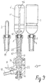
- FIG. 1 Another embodiment is shown in FIG.
- the stretching temple 11 is not hollow but designed massively. At its upper outer, free end it is with a ball 46th Mistake.
- Figure 9 Similar to Figure 6 inert gas, oxygen and here even hydrogen from below from the open end 7 of the container 1 'around the Stretching temple 11 around within the hollow piston 17 and the receptacle 4 vertically upwards from a designated here with 10 supply line and according to the fluid arrows 41 in the warm preform 2 so blown that with the help of the draw punch 11 with his (located at the top) ball 46, the intermediate shape of the container 1 'is formed.
- the check valves 23 operate to the entire Device-side interior to close in the manifold block 14 into the outside.
- the distribution block 14 attached Ignition device 12 which may be arranged, for example, at the place of 8 designated supply line could, the blast gas mixture in the entire device-side interior 22, from the manifold block 14 down to the top in the space of the still in intermediate form container 1 'to Bring explosion.
- the pre-stretching and shaping is shown.
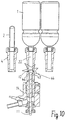
- FIG. 10 is similar in construction to FIG 9, wherein, however, the ignition device 12 above and in the area of the sealing surface 18 of the outer end of the hollow piston 17 is arranged.
- the symbolized by the ignition star 44 Explosion is triggered when the punch 11 is in its lower, retracted position Position is located. Then that is the outer sealing surface of the ball 46 with a Sealing seat 47 in the hollow piston 17 into engagement.
- the device-side interior 22 is located at this embodiment practically only in the area of the receptacle 4, and the ball 46 with the Sealing seat 47 in the hollow piston 17 serves as a check valve 23rd
- FIG. 9 also shows the sealing seat 47 in the hollow piston 17 at the top, in the case of FIG. 9 but then the ignition would have to be removed from the area of the manifold block 14 and be taken up to the area of the intake 4.
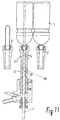
- FIG. 9 Another other embodiment is shown in FIG. Again, the hollow piston 17 is on its receiving 4 facing end provided with a sealing seat 48, a similar Function has the same as the sealing seat 47 in the hollow piston 17 in the embodiment of Figures 9 and 10.
- this annular sealing seat 47 which is frustoconical, enters vertically downwardly tapered, with the radial extension, i. the ball 46 engaged, too can be configured as a cone, ring or the like.
- the ball 46 was according to the figures 9 and 10 is attached all the way to the free upper end of the stretching punch 11.
- the draw punch 11 is solid, i. not hollow. In both embodiments is the device-side interior 22 by the radial extension (ball 46 or shoulder 49) closed to the outside, without a check valve additionally arranged would have to be.
- the further advantage in the embodiment of Figures 9 and 10 is that the Diameter of the stretching punch 11 relative to the draw punch of the hollow embodiment can be very small with the result that a large free cross section in the form of the annulus around the punch 11 around for the injection of fluid (gas mixtures) available stands. This saves time, because the device-side interior 22 with faster the desired fluid can be filled. It is also advantageous that the draw punch 11th becomes less warm in the embodiment of Figures 9 and 10, because only a smaller Part of it is located in the explosion area.
Landscapes
- Engineering & Computer Science (AREA)
- Manufacturing & Machinery (AREA)
- Mechanical Engineering (AREA)
- Blow-Moulding Or Thermoforming Of Plastics Or The Like (AREA)
- Containers Having Bodies Formed In One Piece (AREA)
- Processing And Handling Of Plastics And Other Materials For Molding In General (AREA)
- Basic Packing Technique (AREA)
Description
- Figur 1
- im Schnitt den Transport von Vorformlingen und fertiggeblasenem Behälter über einem Verteiler,
- Figur 2
- ein Diagramm des Druckverlaufes über der Zeit in dem Vorformling bzw. dem herzustellenden Behälter,
- Figur 3a
- die linke Hälfte einer ersten Ausführungsform einer Dosiereinheit, die sich nach rechts mit den abgebrochenen Leitungen fortsetzt,
- Figur 3b
- die rechte Hälfte der Dosiereinheit der Figur 3b, d.h. die Fortsetzung der Leitungen von links her mit dem streckgeblasenen Behälter rechts oben,
- Figur 3c
- die linke Hälfte einer zweiten Ausführungsform einer Dosiereinheit, die sich ebenfalls nach rechts mit den abgebrochenen Leitungen fortsetzt,
- Figur 3d
- die rechte Hälfte der Dosiereinheit der Figur 3c analog der Figur 3b;
- Figur 4
- in vergrößertem Maßstab das obere bzw. behälterseitige Ende des hohl ausgebildeten Streckstempels,
- Figur 5
- das gleiche Ende des Streckstempels wie in Figur 4 im Schnitt dargestellt, hier jedoch perspektivisch,
- Figur 6
- einen Betriebszustand der Vorrichtung, bei welcher im Vergleich zu Figur 1 der in der Mitte unten angeordnete Verteiler mit der Aufnahme dichtend verbunden ist, wobei der Behälter vorgestreckt und geformt wird,
- Figur 7
- einen anderen Zustand des Streck-Blasverfahrens, bei welchem durch Explosion geformt wird,
- Figur 8
- den gleichen Verfahrensschritt wie Figur 7, jedoch perspektivisch und teilweise abgebrochen,
- Figur 9
- mit einer anderen Ausführungsform ein ähnlicher Verfahrensschritt wie bei Figur 6, wobei jedoch das Vorstrecken und Formen durch einen anders ausgestalteten Streckstempel erfolgen,
- Figur 10
- die gleiche Ausführungsform wie in Figur 9, jedoch das Formen durch Explosion,
- Figur 11
- eine ähnliche Darstellung der Vorrichtung wie in den Figuren 7 und 10, wobei eine andere Art von Streckstempel verwendet wird, und
- Figur 12
- vergrößert im Schnitt die Aufnahme mit der oben eingesetzten Zentrierung, durch welche der herzustellende Behälter abgestützt wird.
- 1
- Behälter
- 1'
- teilgeformter Behälter bzw. Zwischenformling
- 2
- Vorformling
- 3
- Pfeil
- 4
- Aufnahme
- 5
- Serviceraum
- 6
- Zentrierung
- 7
- offenes Ende des Behälters
- 8
- Drucksensor
- 8', 8"
- Zuleitung
- 9
- Zuleitung
- 10, 10', 10'a, 10'b
- Zuleitungen
- 11
- Streckstempel
- 12
- Zündeinrichtung
- 13
- Längsmittelachse
- 14
- Verteilerblock
- 15
- durchgehende vertikale Bohrung
- 16
- dichtende Durchführung
- 17
- Hohlkolben
- 18
- Gegendichtfläche
- 19
- ringfömige Dichtfläche
- 20
- Loch
- 21
- Fließmittelanschluß
- 22
- vorrichtungsseitiger Innenraum
- 23
- Rückschlagventil
- 24
- Ventil
- 25
- Misch- und Druckzylinder
- 26
- Gasbehälter
- 27
- Gasbehälter (Argon)
- 28
- Gasbehälter (Wasserstoff)
- 29
- Druckzylinder
- 30
- Spülgasleitung
- 31
- Pfeil
- 32
- Hochspannungserzeugung
- 33
- Streckspitze
- 34
- Stahlrohr
- 35
- Halter
- 36
- Kabel
- 37
- beweglicher Ventilkörper
- 38
- Dichtsitz
- 39
- Innenkanal
- 40
- pneumatischer Anschluß
- 41
- Fluidpfeil
- 42
- H2-Pfeil
- 43
- Pfeil (Gasgemischeinlaß)
- 44
- Stern (Zündung)
- 45
- Auslaß
- 46
- Kugel
- 47
- Dichtsitz im Hohlkolben
- 48
- Dichtsitz im Hohlkolben
- 49
- Schulter
Claims (12)
- Vorrichtung zur Herstellung von Behältern (1, 1') aus einem durch Streck-Blasen verformbaren Kunststoff mit einer Form, deren Innenraum dem fertigen Behälter (1) entspricht, der an seinem offenen Ende (7) von einer Aufnahme (4) gehalten ist, wobei mit einer Dosiereinheit verbundene Leitungen (9, 10) an der Aufnahme (4) vorgesehen sind, ein beweglicher Streckstempel (11) axial durch die Aufnahme (4) geführt ist und eine Zündeinrichtung (12) angeordnet ist, um ein explosives Gasgemisch innerhalb des Behälters (1') zu zünden, und wobei Heiz- und Kühleinrichtungen vorgesehen sind, dadurch gekennzeichnet, daß die Aufnahme (4) an ihrem dem Behälter (1) abgewandten Ende fließmitteldicht mit einem Verteilerblock (14) in Eingriff bringbar ist, durch welchen der Streckstempel (11) in axialer Verlängerung der Aufnahme (4) beweglich hindurchgeführt ist und an welchem wenigstens ein Fließmittelanschluß (9, 10, 21) angebracht ist, daß der vorrichtungsseitige Innenraum (22) im Bereich des wenigstens einen Fließmittelanschlusses (9, 10, 21) zum Abdichten verschließbar ist, daß die Zündeinrichtung (12) in dem vorrichtungsseitigen Innenraum (22) angebracht ist, daß der Streckstempel (11) hohl ausgestaltet ist, mit wenigstens einer an einer Streckspitze (33) angeordneten Austrittsöffnung (20) und mit wenigstens einem die Austrittsöffnung (20) und den Fließmitteleinlaß (21) verbindenden Innenkanal (39) versehen ist und daß vorzugsweise ein Verschließmittel zum Abdichten des vorrichtungsseitigen Innenraumes (22) im Bereich der Austrittsöffnung (20) angebracht ist.
- Vorrichtung nach Anspruch 1, dadurch gekennzeichnet, daß die Aufnahme (4) hohl ist und an ihrem dem Behälter (1) abgewandten Ende eine ringförmige Dichtfläche (19) aufweist, durch welche der Streckstempel (11) in axialer Verlängerung der Aufnahme (4) beweglich hindurchgeführt ist.
- Vorrichtung nach Anspruch 1 oder 2, dadurch gekennzeichnet, daß das Verschließmittel zum Abdichten des vorrichtungsseitigen Innenraumes (22) ein Rückschlagventil (23) ist.
- Vorrichtung nach einem der Ansprüche 1 bis 3, dadurch gekennzeichnet, daß im Bereich der Austrittsöffnung (20) eine Zündeinrichtung (12) in dem hohlen Streckstempel (11) auf der der Austrittsöffnung (20) zugewandten Seite des Rückschlagventiles (23) angebracht und vorzugsweise über in dem hohlen Streckstempel (11) verlaufende Kabel (36) mit einer Steuereinheit elektrisch verbunden ist.
- Vorrichtung nach einem der Ansprüche 1 bis 4, dadurch gekennzeichnet, daß der in Längsrichtung beweglich angetriebene, hohle Streckstempel (11) ein Stahlrohr (34) ist mit einer kappenförmigen Streckspitze (33), an welcher der Fließmittelaustritt (20) in Lochstruktur angebracht ist, und daß das Rückschlagventil (23) einen gegen einen am Stahlrohr (34) innen befestigten Dichtsitz (38) beweglichen und vorzugsweise Wirbelungsmittel tragenden Ventilkörper (37) aufweist.
- Vorrichtung nach einem der Ansprüche 1 bis 5, dadurch gekennzeichnet, daß die Aufnahme (4) senkrecht zu ihrer Längsmittelachse (13) bewegbar angetrieben ist.
- Vorrichtung nach einem der Ansprüche 1 bis 6, dadurch gekennzeichnet, daß die Aufnahme (4) an dem dem Verteilerblock (14) abgewandten Ende zur Bildung eines Serviceraumes (5) erweitert ist, in welchem vorzugsweise eine Zentrierung (6) eingesetzt ist.
- Vorrichtung nach einem der Ansprüche 1 bis 7, dadurch gekennzeichnet, daß in dem vorzugsweise ortsfesten Verteilerblock (14) ein relativ zu diesem axial bewegbar angetriebener Hohlkolben (17) vorgesehen ist, der an seinem äußeren, der Aufnahme (4) zugewandten Ende eine zu der Aufnahme passende, ringförmige Gegendichtfläche (18) aufweist.
- Vorrichtung nach einem der Ansprüche 1 bis 8, dadurch gekennzeichnet, daß in dem Vertellerblock (14) zur Führung des Streckstempels (11) eine dichtende Durchführung (16) in Flucht zu dem Hohlkolben (17) angebracht ist
- Vorrichtung nach einem der Ansprüche 1 bis 9, dadurch gekennzeichnet, daß wenigstens eine mit der Dosiereinheit verbundene Zuführ- (10', 21) und eine Abführleitung (10) an den Verteilerblock (14) angeschlossen sind.
- Vorrichtung nach einem der Ansprüche 1 bis 12, dadurch gekennzeichnet, daß in jeder der an dem Verteilerblock (14) angeschlossenen Zuführ- (9, 10', 21) und Abführleitungen (10) ein Rückschlagventil (23) angeschlossen ist und die Zündeinrichtung (12) in dem Verteilerblock (14) angebracht ist.
- Vorrichtung nach einem der Ansprüche 1 bis 11, dadurch gekennzeichnet, daß der Hohlkolben (17) an seinem der Aufnahme (4) zugewandten Ende einen ringförmigen Dichtsitz (47, 48) aufweist und der Streckstempel (11) an seinem in den herzustellenden Behälter (1, 1') bewegbaren Ende für den Eingriff mit dem Dichtsitz eine senkrecht zu seiner Längsachse (13) radiale Erweiterung (46) trägt.
Applications Claiming Priority (3)
| Application Number | Priority Date | Filing Date | Title |
|---|---|---|---|
| DE19938724A DE19938724A1 (de) | 1999-08-16 | 1999-08-16 | Vorrichtung zur Herstellung von Kunststoffbehältern mittels Streckblasformen |
| DE19938724 | 1999-08-16 | ||
| PCT/EP2000/006604 WO2001012416A1 (de) | 1999-08-16 | 2000-07-12 | Vorrichtung zur herstellung von kunststoffbehältern mittels streckblasformen unter verwendung eines explosiven blasmediums |
Publications (2)
| Publication Number | Publication Date |
|---|---|
| EP1204526A1 EP1204526A1 (de) | 2002-05-15 |
| EP1204526B1 true EP1204526B1 (de) | 2004-05-12 |
Family
ID=7918505
Family Applications (1)
| Application Number | Title | Priority Date | Filing Date |
|---|---|---|---|
| EP00956174A Expired - Lifetime EP1204526B1 (de) | 1999-08-16 | 2000-07-12 | Vorrichtung zur herstellung von kunststoffbehältern mittels streckblasformen unter verwendung eines explosiven blasmediums |
Country Status (11)
| Country | Link |
|---|---|
| US (1) | US6796780B1 (de) |
| EP (1) | EP1204526B1 (de) |
| JP (1) | JP4399138B2 (de) |
| CN (1) | CN1182950C (de) |
| AT (1) | ATE266518T1 (de) |
| AU (1) | AU6822800A (de) |
| CA (1) | CA2381273C (de) |
| DE (2) | DE19938724A1 (de) |
| ES (1) | ES2218202T3 (de) |
| TW (1) | TW558493B (de) |
| WO (1) | WO2001012416A1 (de) |
Families Citing this family (36)
| Publication number | Priority date | Publication date | Assignee | Title |
|---|---|---|---|---|
| DE10065652B4 (de) * | 2000-12-29 | 2007-09-27 | Tetra Laval Holdings & Finance S.A. | Vorrichtung zur Herstellung von Kunststoffbehältern mittels Streckblasformen |
| DE10114401B4 (de) | 2001-03-23 | 2005-03-17 | Tetra Laval Holdings & Finance S.A. | Verfahren zum Blasformen eines Behälters aus Kunststoff und zum Beschichten des Behälterinneren |
| DE10231345A1 (de) | 2002-03-18 | 2003-10-16 | Tetra Laval Holdings & Finance | Vorrichtung zur Herstellung von Kunstoffbehältern mittels Streckblasformen und Vorrichtung zum Beschichten der Innenwände eines Kunstoffbehälters |
| US7059879B2 (en) * | 2004-05-20 | 2006-06-13 | Hubbell Incorporated | Electrical connector having a piston-contact element |
| FR2889672B1 (fr) * | 2005-08-12 | 2009-08-07 | Sidel Sas | Ensemble fonctionnel pour installation de soufflage de recipients et installation comportant un tel ensemble |
| FR2917068B1 (fr) * | 2007-06-07 | 2012-10-12 | Sidel Participations | Recipient en polymere presentant un gradient de cristallinite |
| JP5453896B2 (ja) * | 2009-04-23 | 2014-03-26 | 東洋製罐株式会社 | 延伸ブロー成形方法およびその装置 |
| DE102009020738A1 (de) | 2009-05-11 | 2010-11-25 | Krones Ag | Vorrichtung zum Blasformen von Kunststoffvorformlingen mit reduziertem Totvolumen |
| US7985188B2 (en) | 2009-05-13 | 2011-07-26 | Cv Holdings Llc | Vessel, coating, inspection and processing apparatus |
| MX350703B (es) | 2009-05-13 | 2017-09-14 | Sio2 Medical Products Inc | Metodo de gasificacion para inspeccionar una superficie revestida. |
| WO2013170052A1 (en) | 2012-05-09 | 2013-11-14 | Sio2 Medical Products, Inc. | Saccharide protective coating for pharmaceutical package |
| US9458536B2 (en) | 2009-07-02 | 2016-10-04 | Sio2 Medical Products, Inc. | PECVD coating methods for capped syringes, cartridges and other articles |
| US11624115B2 (en) | 2010-05-12 | 2023-04-11 | Sio2 Medical Products, Inc. | Syringe with PECVD lubrication |
| US9878101B2 (en) | 2010-11-12 | 2018-01-30 | Sio2 Medical Products, Inc. | Cyclic olefin polymer vessels and vessel coating methods |
| JP6114199B2 (ja) * | 2011-02-16 | 2017-04-12 | アムコー リミテッド | 容器プリフォームから容器を形成する装置 |
| US9272095B2 (en) | 2011-04-01 | 2016-03-01 | Sio2 Medical Products, Inc. | Vessels, contact surfaces, and coating and inspection apparatus and methods |
| JO3283B1 (ar) | 2011-04-26 | 2018-09-16 | Sanofi Sa | تركيب يتضمن أفليبيرسيبت, حمض فولينيك, 5- فلورويوراسيل (5- Fu) وإرينوسيتان (FOLFIRI) |
| EP2776603B1 (de) | 2011-11-11 | 2019-03-06 | SiO2 Medical Products, Inc. | Passivierungs-, ph-schutz- oder schmierbeschichtung für arzneimittelverpackung, beschichtungsverfahren und vorrichtung |
| US11116695B2 (en) | 2011-11-11 | 2021-09-14 | Sio2 Medical Products, Inc. | Blood sample collection tube |
| FR2983427B1 (fr) * | 2011-12-01 | 2013-11-29 | Sidel Participations | Dispositif de soufflage comportant une tuyere et un conduit d'alimentation formant un angle obtus |
| US20150297800A1 (en) | 2012-07-03 | 2015-10-22 | Sio2 Medical Products, Inc. | SiOx BARRIER FOR PHARMACEUTICAL PACKAGE AND COATING PROCESS |
| CA2890066C (en) | 2012-11-01 | 2021-11-09 | Sio2 Medical Products, Inc. | Coating inspection method |
| US9903782B2 (en) | 2012-11-16 | 2018-02-27 | Sio2 Medical Products, Inc. | Method and apparatus for detecting rapid barrier coating integrity characteristics |
| JP6382830B2 (ja) | 2012-11-30 | 2018-08-29 | エスアイオーツー・メディカル・プロダクツ・インコーポレイテッド | 医療シリンジ、カートリッジ等上でのpecvd堆積の均一性制御 |
| US9764093B2 (en) | 2012-11-30 | 2017-09-19 | Sio2 Medical Products, Inc. | Controlling the uniformity of PECVD deposition |
| US9662450B2 (en) | 2013-03-01 | 2017-05-30 | Sio2 Medical Products, Inc. | Plasma or CVD pre-treatment for lubricated pharmaceutical package, coating process and apparatus |
| EP2971228B1 (de) | 2013-03-11 | 2023-06-21 | Si02 Medical Products, Inc. | Beschichtete verpackung |
| US9937099B2 (en) | 2013-03-11 | 2018-04-10 | Sio2 Medical Products, Inc. | Trilayer coated pharmaceutical packaging with low oxygen transmission rate |
| DE102013102563A1 (de) * | 2013-03-13 | 2014-09-18 | Krones Ag | Blasformmaschine mit kombinierter Führung und Dichtung der Reckstange |
| US20160017490A1 (en) | 2013-03-15 | 2016-01-21 | Sio2 Medical Products, Inc. | Coating method |
| CN105307940B (zh) * | 2013-06-24 | 2017-05-03 | 帝斯克玛股份有限公司 | 通过施加由拉伸杆控制的压力分布来形成容器的方法 |
| DE102014001446A1 (de) * | 2014-01-31 | 2015-08-06 | Kocher-Plastik Maschinenbau Gmbh | Vorrichtung zum Herstellen von Behältererzeugnissen aus Kunststoffmaterial |
| WO2015148471A1 (en) | 2014-03-28 | 2015-10-01 | Sio2 Medical Products, Inc. | Antistatic coatings for plastic vessels |
| EA035674B1 (ru) | 2014-07-18 | 2020-07-24 | Санофи | Способ определения того, является ли пациент, предположительно страдающий от рака, кандидатом для терапии афлиберцептом |
| EP3337915B1 (de) | 2015-08-18 | 2021-11-03 | SiO2 Medical Products, Inc. | Pharmazeutische und andere verpackungen mit niedriger sauerstoffübertragungsrate |
| DE102022117857A1 (de) | 2022-04-25 | 2023-10-26 | Khs Gmbh | Verfahren zum Blasformen von Vorformlingen sowie Blasformanlage |
Family Cites Families (10)
| Publication number | Priority date | Publication date | Assignee | Title |
|---|---|---|---|---|
| US3252312A (en) * | 1962-04-25 | 1966-05-24 | Continental Can Co | Method and apparatus for explosive reshaping of hollow ductile objects |
| GB1436538A (en) * | 1972-11-17 | 1976-05-19 | Dale Ltd John | Manufacture of articles such as collapsible tubes |
| DE2742693C2 (de) | 1977-09-22 | 1983-08-11 | Gildemeister Corpoplast Gmbh, 2000 Hamburg | Maschine zum Blasformen von Hohlkörpern, insbesondere von Flaschen, aus thermoplastischem Kunststoff |
| JPS5627330A (en) * | 1979-08-15 | 1981-03-17 | Yoshino Kogyosho Co Ltd | Heat treatment for internal wall surface of saturated polyester resin biaxially stretched bottle |
| US4457352A (en) * | 1980-03-14 | 1984-07-03 | Scheffer Karl D | System and process for the abatement of casting pollution, reclaiming resin bonded sand, and/or recovering a low BTU fuel from castings |
| US4473515A (en) * | 1980-09-02 | 1984-09-25 | Ryder Leonard B | Injection blow molding method |
| CH690002A5 (fr) * | 1995-10-10 | 2000-03-15 | Tetra Pak Plastics Ltd Tetra P | Machine pour la fabrication de récipient en matière plastique. |
| CH691218A5 (de) * | 1996-08-14 | 2001-05-31 | Tetra Laval Holdings & Finance | Verfahren zur Sterilisation von Oberflächen von beliebigen Gegenständen. |
| NL1003827C2 (nl) * | 1996-08-19 | 1998-02-26 | Thomassen & Drijver | Inrichting voor het hermodelleren van een hol metalen voorwerp. |
| DE10065652B4 (de) | 2000-12-29 | 2007-09-27 | Tetra Laval Holdings & Finance S.A. | Vorrichtung zur Herstellung von Kunststoffbehältern mittels Streckblasformen |
-
1999
- 1999-08-16 DE DE19938724A patent/DE19938724A1/de not_active Ceased
-
2000
- 2000-07-12 CN CNB008117969A patent/CN1182950C/zh not_active Expired - Lifetime
- 2000-07-12 JP JP2001516741A patent/JP4399138B2/ja not_active Expired - Lifetime
- 2000-07-12 AT AT00956174T patent/ATE266518T1/de active
- 2000-07-12 CA CA002381273A patent/CA2381273C/en not_active Expired - Lifetime
- 2000-07-12 WO PCT/EP2000/006604 patent/WO2001012416A1/de not_active Ceased
- 2000-07-12 AU AU68228/00A patent/AU6822800A/en not_active Abandoned
- 2000-07-12 US US10/049,559 patent/US6796780B1/en not_active Expired - Lifetime
- 2000-07-12 EP EP00956174A patent/EP1204526B1/de not_active Expired - Lifetime
- 2000-07-12 ES ES00956174T patent/ES2218202T3/es not_active Expired - Lifetime
- 2000-07-12 DE DE50006429T patent/DE50006429D1/de not_active Expired - Lifetime
- 2000-09-15 TW TW089116540A patent/TW558493B/zh not_active IP Right Cessation
Also Published As
| Publication number | Publication date |
|---|---|
| CA2381273C (en) | 2008-05-20 |
| US6796780B1 (en) | 2004-09-28 |
| JP4399138B2 (ja) | 2010-01-13 |
| ATE266518T1 (de) | 2004-05-15 |
| DE19938724A1 (de) | 2001-02-22 |
| TW558493B (en) | 2003-10-21 |
| CN1182950C (zh) | 2005-01-05 |
| WO2001012416A1 (de) | 2001-02-22 |
| DE50006429D1 (de) | 2004-06-17 |
| CN1370108A (zh) | 2002-09-18 |
| EP1204526A1 (de) | 2002-05-15 |
| CA2381273A1 (en) | 2001-02-22 |
| JP2003507208A (ja) | 2003-02-25 |
| AU6822800A (en) | 2001-03-13 |
| ES2218202T3 (es) | 2004-11-16 |
Similar Documents
| Publication | Publication Date | Title |
|---|---|---|
| EP1204526B1 (de) | Vorrichtung zur herstellung von kunststoffbehältern mittels streckblasformen unter verwendung eines explosiven blasmediums | |
| EP1487628B1 (de) | Vorrichtung zur herstellung von kunststoffbehältern mittels streckblasformen | |
| DE69800516T2 (de) | Blasdorn für behälter aus kunststoff und vorrichtung die so einen blasdorn verwendet | |
| EP2054209B1 (de) | Verfahren zur Herstellung eines mehrschichtigen Vorformlings sowie Düse hierfür | |
| EP2125524B1 (de) | Vorrichtung zum minimieren des sauerstoffgehaltes | |
| WO2012104019A1 (de) | Verfahren sowie vorrichtung zum herstellen von mit einem flüssigen füllgut gefüllten behältern | |
| EP2516133A1 (de) | Verfahren und vorrichtung zur herstellung von gefüllten behältern | |
| DE1604689B2 (de) | Verfahren und vorrichtung zum herstellen eines biaxial orientierten hohlkoerpers | |
| DE1479550A1 (de) | Verfahren und Vorrichtung zum Herstellen geblasener Kunststoff-Gegenstaende | |
| EP2730390B1 (de) | Verfahren zur gewährleistung der masshaltigkeit einer ausgiessöffnung in bzw. an einem in einem extrusionsblasverfahren hergestellten kunststoffbehälter | |
| EP4168240B1 (de) | Verfahren und vorrichtung zum herstellen von behältern aus thermisch konditionierten vorformlingen aus thermoplastischem material | |
| DD270492A5 (de) | Vorrichtung zum herstellen eines einerends offenen und anderenends geschlossenen kunststoff-hohlkoerpers | |
| DE10065652B4 (de) | Vorrichtung zur Herstellung von Kunststoffbehältern mittels Streckblasformen | |
| DE1479536A1 (de) | Verfahren zum Herstellen von Hohlkoerpern aus thermoplastischem Kunststoff im Blasverfahren | |
| DE69229058T2 (de) | Verfahren zum blasformen von rohrfoermigen behaeltern | |
| DE1479656A1 (de) | Verfahren und Geraet zur Herstellung von Hohlgegenstaenden aus plastischen Massen | |
| CH433096A (de) | Verfahren und Vorrichtung zum Formen, Füllen und Verschliessen von Behältern | |
| DE1098703B (de) | Verfahren und Vorrichtung zum Herstellen von Flaschen aus einem thermoplastischen Kunststoff nach der Methode des Blasens | |
| DE3108912A1 (de) | Verfahren zur entfernung loser partikel aus bechern und vorrichtung zur durchfuehrung des verfahrens | |
| DE2220301A1 (de) | Verfahren und Vorrichtung zum Herstellen von Hohlkörpern aus Kunststoff | |
| DE102023004512A1 (de) | Vorrichtung zum Blasformen und Befüllen von Behältnissen | |
| AT273814B (de) | Vorrichtung zum Formen von Behältern aus Kunststoff | |
| DE1479757C (de) | Verfahren zur Herstellung hohler Ge genstande aus thermoplastischem Kunststoff | |
| DE1479554C3 (de) | Verfahren und Vorrichtung zum Herstellen von Hohlkörpern aus thermoplastischem Kunststoff durch kombiniertes Spritzgießen, Strangpressen und Formblasen | |
| DE1111810B (de) | Verfahren zum Herstellen von Flaschen od. dgl. aus thermoplastischem Kunststoff |
Legal Events
| Date | Code | Title | Description |
|---|---|---|---|
| PUAI | Public reference made under article 153(3) epc to a published international application that has entered the european phase |
Free format text: ORIGINAL CODE: 0009012 |
|
| 17P | Request for examination filed |
Effective date: 20020128 |
|
| AK | Designated contracting states |
Kind code of ref document: A1 Designated state(s): AT BE CH CY DE DK ES FI FR GB GR IE IT LI LU MC NL PT SE |
|
| AX | Request for extension of the european patent |
Free format text: AL;LT;LV;MK;RO;SI |
|
| 17Q | First examination report despatched |
Effective date: 20020624 |
|
| GRAP | Despatch of communication of intention to grant a patent |
Free format text: ORIGINAL CODE: EPIDOSNIGR1 |
|
| GRAS | Grant fee paid |
Free format text: ORIGINAL CODE: EPIDOSNIGR3 |
|
| GRAA | (expected) grant |
Free format text: ORIGINAL CODE: 0009210 |
|
| AK | Designated contracting states |
Kind code of ref document: B1 Designated state(s): AT BE CH CY DE DK ES FI FR GB GR IE IT LI LU MC NL PT SE |
|
| PG25 | Lapsed in a contracting state [announced via postgrant information from national office to epo] |
Ref country code: CY Free format text: LAPSE BECAUSE OF FAILURE TO SUBMIT A TRANSLATION OF THE DESCRIPTION OR TO PAY THE FEE WITHIN THE PRESCRIBED TIME-LIMIT Effective date: 20040512 Ref country code: IE Free format text: LAPSE BECAUSE OF FAILURE TO SUBMIT A TRANSLATION OF THE DESCRIPTION OR TO PAY THE FEE WITHIN THE PRESCRIBED TIME-LIMIT Effective date: 20040512 Ref country code: FI Free format text: LAPSE BECAUSE OF FAILURE TO SUBMIT A TRANSLATION OF THE DESCRIPTION OR TO PAY THE FEE WITHIN THE PRESCRIBED TIME-LIMIT Effective date: 20040512 |
|
| REG | Reference to a national code |
Ref country code: GB Ref legal event code: FG4D Free format text: NOT ENGLISH |
|
| RIN1 | Information on inventor provided before grant (corrected) |
Inventor name: CHATARD, DOMINIQUE Inventor name: WILHELM, LOTHAR Inventor name: SENDOBRY, EBERHARD Inventor name: KUHN, ROLF Inventor name: KINDINGER, HANS Inventor name: FUCHS, JENS Inventor name: RIEDEL, THOMAS Inventor name: WLACH, RUEDIGER |
|
| REG | Reference to a national code |
Ref country code: CH Ref legal event code: EP |
|
| REG | Reference to a national code |
Ref country code: IE Ref legal event code: FG4D Free format text: GERMAN |
|
| REF | Corresponds to: |
Ref document number: 50006429 Country of ref document: DE Date of ref document: 20040617 Kind code of ref document: P |
|
| PG25 | Lapsed in a contracting state [announced via postgrant information from national office to epo] |
Ref country code: LU Free format text: LAPSE BECAUSE OF NON-PAYMENT OF DUE FEES Effective date: 20040712 |
|
| REG | Reference to a national code |
Ref country code: CH Ref legal event code: NV Representative=s name: ISLER & PEDRAZZINI AG |
|
| PG25 | Lapsed in a contracting state [announced via postgrant information from national office to epo] |
Ref country code: MC Free format text: LAPSE BECAUSE OF NON-PAYMENT OF DUE FEES Effective date: 20040731 |
|
| PG25 | Lapsed in a contracting state [announced via postgrant information from national office to epo] |
Ref country code: GR Free format text: LAPSE BECAUSE OF FAILURE TO SUBMIT A TRANSLATION OF THE DESCRIPTION OR TO PAY THE FEE WITHIN THE PRESCRIBED TIME-LIMIT Effective date: 20040812 Ref country code: DK Free format text: LAPSE BECAUSE OF FAILURE TO SUBMIT A TRANSLATION OF THE DESCRIPTION OR TO PAY THE FEE WITHIN THE PRESCRIBED TIME-LIMIT Effective date: 20040812 |
|
| REG | Reference to a national code |
Ref country code: SE Ref legal event code: TRGR |
|
| GBT | Gb: translation of ep patent filed (gb section 77(6)(a)/1977) |
Effective date: 20040809 |
|
| LTIE | Lt: invalidation of european patent or patent extension |
Effective date: 20040512 |
|
| REG | Reference to a national code |
Ref country code: ES Ref legal event code: FG2A Ref document number: 2218202 Country of ref document: ES Kind code of ref document: T3 |
|
| ET | Fr: translation filed | ||
| REG | Reference to a national code |
Ref country code: IE Ref legal event code: FD4D |
|
| PLBE | No opposition filed within time limit |
Free format text: ORIGINAL CODE: 0009261 |
|
| STAA | Information on the status of an ep patent application or granted ep patent |
Free format text: STATUS: NO OPPOSITION FILED WITHIN TIME LIMIT |
|
| 26N | No opposition filed |
Effective date: 20050215 |
|
| REG | Reference to a national code |
Ref country code: CH Ref legal event code: PCAR Free format text: ISLER & PEDRAZZINI AG;POSTFACH 1772;8027 ZUERICH (CH) |
|
| PG25 | Lapsed in a contracting state [announced via postgrant information from national office to epo] |
Ref country code: PT Free format text: LAPSE BECAUSE OF NON-PAYMENT OF DUE FEES Effective date: 20041012 |
|
| REG | Reference to a national code |
Ref country code: FR Ref legal event code: PLFP Year of fee payment: 17 |
|
| REG | Reference to a national code |
Ref country code: FR Ref legal event code: PLFP Year of fee payment: 18 |
|
| REG | Reference to a national code |
Ref country code: FR Ref legal event code: PLFP Year of fee payment: 19 |
|
| PGFP | Annual fee paid to national office [announced via postgrant information from national office to epo] |
Ref country code: BE Payment date: 20190617 Year of fee payment: 20 Ref country code: FR Payment date: 20190619 Year of fee payment: 20 Ref country code: NL Payment date: 20190712 Year of fee payment: 20 |
|
| PGFP | Annual fee paid to national office [announced via postgrant information from national office to epo] |
Ref country code: DE Payment date: 20190702 Year of fee payment: 20 Ref country code: SE Payment date: 20190710 Year of fee payment: 20 Ref country code: IT Payment date: 20190719 Year of fee payment: 20 Ref country code: ES Payment date: 20190802 Year of fee payment: 20 |
|
| PGFP | Annual fee paid to national office [announced via postgrant information from national office to epo] |
Ref country code: AT Payment date: 20190625 Year of fee payment: 20 Ref country code: GB Payment date: 20190710 Year of fee payment: 20 |
|
| PGFP | Annual fee paid to national office [announced via postgrant information from national office to epo] |
Ref country code: CH Payment date: 20190718 Year of fee payment: 20 |
|
| REG | Reference to a national code |
Ref country code: DE Ref legal event code: R071 Ref document number: 50006429 Country of ref document: DE |
|
| REG | Reference to a national code |
Ref country code: CH Ref legal event code: PL |
|
| REG | Reference to a national code |
Ref country code: GB Ref legal event code: PE20 Expiry date: 20200711 |
|
| REG | Reference to a national code |
Ref country code: NL Ref legal event code: MK Effective date: 20200711 |
|
| REG | Reference to a national code |
Ref country code: AT Ref legal event code: MK07 Ref document number: 266518 Country of ref document: AT Kind code of ref document: T Effective date: 20200712 |
|
| REG | Reference to a national code |
Ref country code: BE Ref legal event code: MK Effective date: 20200712 |
|
| REG | Reference to a national code |
Ref country code: SE Ref legal event code: EUG |
|
| REG | Reference to a national code |
Ref country code: SE Ref legal event code: EUG |
|
| REG | Reference to a national code |
Ref country code: ES Ref legal event code: FD2A Effective date: 20201026 |
|
| PG25 | Lapsed in a contracting state [announced via postgrant information from national office to epo] |
Ref country code: GB Free format text: LAPSE BECAUSE OF EXPIRATION OF PROTECTION Effective date: 20200711 |
|
| PG25 | Lapsed in a contracting state [announced via postgrant information from national office to epo] |
Ref country code: ES Free format text: LAPSE BECAUSE OF EXPIRATION OF PROTECTION Effective date: 20200713 |