EP1204581B1 - Verfahren zum kontinuierlichen aufwickeln von papier und wickler - Google Patents
Verfahren zum kontinuierlichen aufwickeln von papier und wickler Download PDFInfo
- Publication number
- EP1204581B1 EP1204581B1 EP00922686A EP00922686A EP1204581B1 EP 1204581 B1 EP1204581 B1 EP 1204581B1 EP 00922686 A EP00922686 A EP 00922686A EP 00922686 A EP00922686 A EP 00922686A EP 1204581 B1 EP1204581 B1 EP 1204581B1
- Authority
- EP
- European Patent Office
- Prior art keywords
- reel
- paper
- reeling
- nip contact
- paper reel
- Prior art date
- Legal status (The legal status is an assumption and is not a legal conclusion. Google has not performed a legal analysis and makes no representation as to the accuracy of the status listed.)
- Expired - Lifetime
Links
Images





Classifications
-
- B—PERFORMING OPERATIONS; TRANSPORTING
- B65—CONVEYING; PACKING; STORING; HANDLING THIN OR FILAMENTARY MATERIAL
- B65H—HANDLING THIN OR FILAMENTARY MATERIAL, e.g. SHEETS, WEBS, CABLES
- B65H19/00—Changing the web roll
- B65H19/22—Changing the web roll in winding mechanisms or in connection with winding operations
- B65H19/2238—The web roll being driven by a winding mechanism of the nip or tangential drive type
-
- B—PERFORMING OPERATIONS; TRANSPORTING
- B65—CONVEYING; PACKING; STORING; HANDLING THIN OR FILAMENTARY MATERIAL
- B65H—HANDLING THIN OR FILAMENTARY MATERIAL, e.g. SHEETS, WEBS, CABLES
- B65H18/00—Winding webs
- B65H18/08—Web-winding mechanisms
- B65H18/14—Mechanisms in which power is applied to web roll, e.g. to effect continuous advancement of web
- B65H18/22—Mechanisms in which power is applied to web roll, e.g. to effect continuous advancement of web by friction band
-
- B—PERFORMING OPERATIONS; TRANSPORTING
- B65—CONVEYING; PACKING; STORING; HANDLING THIN OR FILAMENTARY MATERIAL
- B65H—HANDLING THIN OR FILAMENTARY MATERIAL, e.g. SHEETS, WEBS, CABLES
- B65H18/00—Winding webs
- B65H18/08—Web-winding mechanisms
- B65H18/26—Mechanisms for controlling contact pressure on winding-web package, e.g. for regulating the quantity of air between web layers
-
- B—PERFORMING OPERATIONS; TRANSPORTING
- B65—CONVEYING; PACKING; STORING; HANDLING THIN OR FILAMENTARY MATERIAL
- B65H—HANDLING THIN OR FILAMENTARY MATERIAL, e.g. SHEETS, WEBS, CABLES
- B65H19/00—Changing the web roll
- B65H19/22—Changing the web roll in winding mechanisms or in connection with winding operations
- B65H19/30—Lifting, transporting, or removing the web roll; Inserting core
-
- B—PERFORMING OPERATIONS; TRANSPORTING
- B65—CONVEYING; PACKING; STORING; HANDLING THIN OR FILAMENTARY MATERIAL
- B65H—HANDLING THIN OR FILAMENTARY MATERIAL, e.g. SHEETS, WEBS, CABLES
- B65H19/00—Changing the web roll
- B65H19/22—Changing the web roll in winding mechanisms or in connection with winding operations
- B65H19/30—Lifting, transporting, or removing the web roll; Inserting core
- B65H19/305—Inserting core
-
- B—PERFORMING OPERATIONS; TRANSPORTING
- B65—CONVEYING; PACKING; STORING; HANDLING THIN OR FILAMENTARY MATERIAL
- B65H—HANDLING THIN OR FILAMENTARY MATERIAL, e.g. SHEETS, WEBS, CABLES
- B65H2301/00—Handling processes for sheets or webs
- B65H2301/40—Type of handling process
- B65H2301/41—Winding, unwinding
- B65H2301/413—Supporting web roll
- B65H2301/4137—Supporting web roll on its outer circumference
- B65H2301/41372—Supporting web roll on its outer circumference rollers or balls arrangement
- B65H2301/41376—Supporting web roll on its outer circumference rollers or balls arrangement arranged in a non-stationary manner, i.e. changing according to actual roll diameter
Definitions
- the invention relates to a method according to the preamble of claim 1 in continuous reeling up of a paper web.
- the invention also relates to a reel-up according to the preamble of the independent claim relating to the reel-up.
- the reel-up is primarily characterized in that the reel-up comprises:
- FIG. 8 shows a side-view of the general principle of the method according to the invention.
- a closed supporting belt rotation 1 brings the paper web PR on the outer surface of a paper reel R, wherein the paper web is transferred from the outer surface of the supporting belt rotation directly to the paper reel R to be formed on a reeling core 6.
- a first nip contact SN is established.
- the reeling core 6 is stationary with respect to the machine frame, wherein the supporting belt rotation 1 and the first nip contact SN therein are transferred substantially upwards in the direction of arrow Y when the diameter of the paper reel R grows.
- the transfer direction can be either directly downwards in accordance with arrow A, or as a combination with the downward directed movement of the arrow, horizontally in the direction of arrow V, wherein the combined effect of the aforementioned movements is directed as a resultant R diagonally downwards.
- the location of the second nip contact PN can vary ⁇ 60° from the vertical line running via the centre of the reeling core 6, wherein the ⁇ 60° angular point of the angles opening downwards is located in the fulcrum RYK of the reeling core.
- the second nip contact PN is advantageously arranged to affect the paper reel R that is being formed, both in the direction of the periphery and the radius of the paper reel, wherein on the periphery of the paper reel R that is being formed, the second nip contact PN covers more than 2% of the outer surface of the paper reel R that is being formed in the direction of the periphery of the paper reel R.
- the first nip contact SN is a so-called secondary nip contact, the purpose of which is to minimize the access of air between the layers of paper formed on the paper reel R and to ensure the quality of the paper reel that is being formed.
- the second nip contact PN is intended as a so-called primary nip contact, the purpose of which is to control the formation of the paper reel R.
- the contact force of the second PN or so-called primary nip contact in the direction of the radius of the paper reel R is effected in such a manner that a vertical component A of the contact force constitutes at least half of the total magnitude of the contact force.
- the reel-up comprises a closed supporting belt rotation 1 functioning as a guiding means for the paper web, which supporting belt rotation 1 is established by means of guiding reels 2a, via which the endless supporting belt 1 a rotates.
- the supporting belt rotation 1 is connected to the end of the drying section, from which the paper web is passed on top of the supporting belt rotation to be guided to the reeling up stage.
- a reel change threading apparatus 4 Inside the supporting belt rotation there is a reel change threading apparatus 4 that forms a continuous surface, the function of the apparatus for the part of certain operations being described in more detail hereinbelow.
- the ends of the reel change threading apparatus 4 are provided with reels 2a, 2b participating in the guidance of the travel of the supporting belt rotation 1 and belonging to the means for establishing a nip contact, especially to the means for establishing a so-called secondary nip contact, i.e. the reel 2a constitutes a first nip member part and the reel 2b a second nip member part. Furthermore, the end of the supporting belt loop 1 accommodating the first nip member part 2a is provided with means for cutting the end of the paper web, i.e. a cutting device 5.
- a cutting device 5 In the first embodiment of the reel-up according to Figs.
- the paper web rotates counterclockwise in accordance with arrow K to the reeling cores 6 and 7, first passing the reel change threading apparatus 4 in the machine direction on top of the supporting belt loop 1, in a substantially horizontal position, travelling away from the end of the drying section 3 and turning towards the drying section 3 at the location of the cutting device and further to the reeling core 6 or 7 in question.
- the first basic embodiment of the invention is characterized in that two sets of reeling cores - a first and a second reeling core set - are established.
- the reference numeral 6 represents a reeling core belonging to the first reeling core set
- the reference numeral 7 represents a reeling core belonging to the second reeling core set.
- the reeling cores 6 and 7, which are located in the reeling up station, are placed successively on the same horizontal level in the machine direction, within a horizontal distance from each other in such a way that their central axles are parallel to each other. In the vertical direction, the central axles of the reeling cores 6 and 7 are substantially located by the first 2a and second nip member part 2a, respectively.
- the reeling cores 6 and 7 are supported from underneath by means of nip member parts 8 and 9 (the reference numeral 8 indicating a third nip member part and the reference numeral 9 a fourth nip member part) for establishing a so-called primary nip contact, which nip member parts belong to the means for establishing a nip contact.
- nip member parts 8 and 9 the reference numeral 8 indicating a third nip member part and the reference numeral 9 a fourth nip member part
- the first 2a and the second 2b nip member part are intended for establishing a so-called secondary nip contact to ensure the quality of the paper reel that is being formed, e.g. to prevent the access of air between the paper layers.
- the third 8 and the fourth nip member part 9, in turn, are intended for establishing a so-called primary nip contact, i.e. to control the formation of the paper reel, in other words the primary nip contact is utilized to attain a paper reel of desired quality.
- the nip member parts 8, 9 establishing the first or primary nip contact are located below the central axle of the reeling core 6.
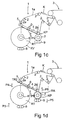
- Fig. 1 a shows a situation in which the filling of the reeling core 6 (reel RA) belonging to the first reeling core set is started after the reeling core 7 belonging to the second reeling core set has become full, by guiding the end of the paper web cut by means of the cutting device 5 directly to the reeling core 6.
- the reeling up process to the reeling core 6 has proceeded so far that the preceding full paper reel has been removed and a new reeling core 7 belonging to the second reeling core set has been brought to the change station.
- the fulcrum of the reeling cores 6 and 7 remains substantially stationary with respect to the machine frame during the reeling up process, and the third nip member part 8 is transferred downward in the direction of the arrow P1 (Fig. 1 b) so that it maintains the nip contact when the size of the paper reel grows.
- the secondary nip contact is maintained by the first nip member part 2a. This stage is illustrated in Fig. 1b.
- the paper reel R1 which is formed on the first reeling core 6 has become full, and the reel change threading (the end KP of the cut paper web) has to be conducted by means of the reel change threading apparatus 4 to the reeling core 7 belonging to the second reeling core set, passing the full paper reel R1 formed on the reeling core 6 belonging to the first reeling core set in the machine direction (the end of the paper web remaining on the paper reel R1 being indicated by the letters KV).
- the reel change threading apparatus 4 is detached from the full reel R1 when the reeling of the paper reel to be formed on the reeling core 7 has begun (reel RA) and the full paper reel R1 is ready to be removed after a stoppage.
- the threading unit PV which contains a reel change threading apparatus 4, a first nip member part 2a, a second nip member part 2b and a cutting device 5 for paper web, is transferred vertically during the reeling up process.
- the end of the threading unit PV accommodating the first nip member part 2a is transferred upward when the formation of the paper reel proceeds, and in a corresponding manner, of course, the end of the threading unit PV at the location of the second reeling core 7 is transferred downward towards the reeling core which is to filled at the next stage (cf. arrow P2 in Fig.
- the threading unit PV operates in a corresponding manner, but with the opposite direction of motion, in the reeling up process of a paper reel formed on the second reeling core 7 (i.e. when shifting from the stage according to Fig. 1d to the stage according to Fig. 1a).
- the first nip member part 2a is in a position TR2 corresponding to the removal of the full reel R1, from which it is transferred downward (arrow P4) into a nip contact with the reeling core 6.
- the fourth nip member part 9 is substantially in its upper position due to the presentation sequence, and naturally it moves in corresponding directions (i.e. in the situation of Fig. 1d the nip member part 9 is transferred downwards, arrow P5 and the second nip member part 2b upwards, arrow P6).
- the threading unit PV can be arranged to be transferred in the vertical direction, advantageously to swing with respect to its centre O (In Figs. 1a to d corresponding arrows represent the direction of rotation) by means of suitable members (not shown in the drawings).
- Figs. 2a to f illustrate the functions of the basic embodiment according to Fig. 1, seen from the top.
- Figs. 2a and 2b substantially correspond to a situation which is shown from the side in Fig. 1a.
- a full paper reel has been removed from the location of the fourth nip member part 9, in a direction transverse to the machine direction to an arranging station located outside the supporting belt rotation 1, and a new reeling core 7 is fixed on the supporting frame (see Figs. 3 and 4), wherein the reeling core 7 and its supporting frame are transferred in a direction transverse to the machine direction (arrow S1) to the corresponding reeling up station (i.e. reel change station) RVA.
- Fig. 2a shows a situation in which the paper reel forming around the reeling core 6 is at the formation stage, and the second reeling core 7 is placed in a direction transverse to the machine direction to be positioned at the location of the second nip member part in such a manner, however, that the corresponding second drive 10b is not yet switched on.
- Fig. 2a shows a situation in which the paper reel forming around the reeling core 6 is at the formation stage, and the second reeling core 7 is placed in a direction transverse to the machine direction to be positioned at the location of the second nip member part in such a manner, however, that the corresponding second drive 10b is not yet switched on.
- FIG. 2c the formation of the paper reel to be formed on the first reeling core 6 proceeds to such a stage in which the second drive 10b is already switched on and the acceleration of the second reeling core 7 and a "capture" of the second nip member part 2b take place, wherein at the final stage of the situation according to Fig. 2c, it is possible to cut the paper web by means of the cutting device 5 and conduct the threading of the end of the cut paper web by means of the reel change threading apparatus 4 to the second reeling core.
- Fig. 2d illustrates this situation, wherein the reeling to the second reeling core 7 is already in progress, and the paper reel formed on the first reeling core 6 is decelerated.
- the reeling cores 6, 7 belonging to both reeling core sets can be completely similar to each other, a substantial functional difference being the fact that to the reeling cores 6 belonging to the first set, the paper web is brought directly from the end of the threading unit PV and to the reeling cores 7 belonging to the second set via the reel change threading apparatus 4.
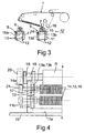
- the supporting frame used for the reeling cores 6, 7 is a reeling carriage 11, which constitutes a fixing frame, on one hand for the means establishing the so-called primary nip contact, i.e. to the third 8 and fourth nip member part 9, and on the other hand for the reeling cores 6 and 7.
- the cross-section of the fixing frame in the vertical plane perpendicular to the machine direction is U-shaped, wherein the formation of the paper reel takes place partly into the U-shape.
- the bottom 11a of the fixing frame is provided with a guide arrangement cooperating with the guide means placed on the base on which the reel-up is positioned.
- This guide means by means of which the reeling carriage 11 can be transferred in a direction transverse to the machine direction at the point of location of the supporting belt assembly 1 in the vertical direction and away from underneath the supporting belt assembly 1 to the arranging station JA, is generally marked with the reference numeral 12.
- Both vertical parts 11b of the U-shaped cross-section of the reeling carriage 11 are provided with a vertical guide arrangement 13, on the support of which the nip member parts 8 and 9 are able to move in the vertical direction.
- the nip member parts 8 and 9 are formed as a belt roll assembly 14, 15, 16, wherein the two adjacent vertical guides 13a, 13b in the guide arrangement 13 constitute a vertical guide line for the guiding carriages or the like 17 of the belt roll assembly.
- the belt roll assembly is formed by at least two rolls 14, 15, of which at least one 14 is driving, as well as an endless belt 16 between these rolls forming a supporting texture rotation, the paper reel that is being formed resting on the upper central part 16a of the same during the formation of the paper reel.
- the reeling core 6, 7 is supported by means of locking jaws 19 protruding from the upper edge of the vertical parts 11 b in the U-shaped cross section of the reeling carriage.
- the reeling core 6, 7 contains a bearing housing 18, and the reeling core is extended by a switch 20 of the centre-drive, which is connected to a drive 10a, 10b according to Fig. 2.
- the axle 14a of the driving roll 14 is extended by a switch 21 by means of which the drive of the belt roll assembly is switched on (the switch is not shown).
- unbroken lines illustrate the position of the belt roll assembly 14, 15, 16 at a particular formation stage of the paper reel R, and furthermore, broken lines illustrate another position of the belt roll assembly 14, 15, 16, in which it is when the paper reel becomes full.
- the belt roll assembly is shown with dotted lines, and the paper web with an unbroken line, wherein the second reeling core 7 is at the reeling up stage.
- the rolls 14, 15 of the belt roll assembly can be lowered in the guides 13a, 13b of the guide arrangement, either at the same speed when the endless belt 16 is in a substantially horizontal position, wherein the loading affects vertically on the central part of the endless belt 16, or at least partly at different times or simultaneously in such a manner that the endless belt 16 lies in a diagonal position, wherein the loading affects diagonally with respect to the vertical direction.
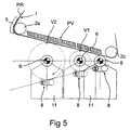
- the second basic embodiment of the invention functions for the part of the threading unit PV in a substantially similar manner as the first basic embodiment, but in view of applying the invention, it is now stationary and the reeling carriage 11, the basic structure of which can be substantially similar to the one described in connection with Figs. 3 and 4, moves in that direction in the machine direction in which the reel change threading apparatus 4 is directed upwards.
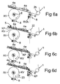
- Figs. 6a to d illustrates a side-view of a reel change situation, wherein when the full paper reel R1 has become full when it is located at the end of the gap, a new reeling core 6' and the reeling carriage 11 have been brought to the reel change station in a corresponding manner, i.e. in contact with the reel change threading apparatus 4, for example with the end of the same.
- Fig. 6 shows a reel change threading apparatus 4 as a series of successive parallelograms 4a, which illustrate members, for example suction boxes, each of which can be preferably separately activated to a suction effect to guide the cut end of the web in the reel change situation to the reeling core 6' positioned in the reel change station RVA.
- Fig. 6 shows a reel change threading apparatus 4 as a series of successive parallelograms 4a, which illustrate members, for example suction boxes, each of which can be preferably separately activated to a suction effect to guide the cut end of the web in the reel change situation to the reeling core 6
- Fig. 6a schematically illustrates the cutting stage of the end of the paper web, performed e.g. by means of the cutting device 5.
- the entire reel change threading apparatus 4 is activated, i.e. the suction effect is switched on, wherein the cut end P of the paper web passes the full reel R1 under the control of the supporting belt assembly 1, being supported from above and it is transferred to a second reeling core 6' in the reel change station RVA.
- Fig. 6c illustrates a situation in which the cut end KP of the paper web is transferred towards the second reeling core 6 under the guidance of the reel change threading apparatus 4 and furthermore, Fig. 6e illustrates a situation in which formation of the paper reel on the new reeling core 6' is already starting and the full paper reel R1 is decelerated (arrow 23).
- the supporting belt assembly 1 is illustrated by means of dotted lines, the paper web positioned on the paper reel R1 that is becoming full or on a full paper reel R1 with a thin, unbroken line, and the paper web passed on the new reeling core 6' with a thick broken line.
- the cut end of the paper web is represented with the letter combination KP.
- the end of the paper web remaining on the preceding full paper reel is marked with the letter combination KV.
- Fig. 7 shows the stages which relate to the implementation of the second basic embodiment of the invention, especially when seen from the above.
- Fig. 7a the reeling of the paper web on the reeling core 6 has been started in the reel change station RVA.
- the first drive 24 is then switched on.
- Fig. 7b the paper reel that is becoming full proceeds in the gap (arrow 25; unbroken lines) leaving the reel change station RVA (dotted lines).
- Fig. 7 shows the stages which relate to the implementation of the second basic embodiment of the invention, especially when seen from the above.
Landscapes
- Replacement Of Web Rolls (AREA)
- Winding Of Webs (AREA)
Claims (22)
- Aufrollverfahren, bei dem ununterbrochen Papierrollen von einer Endlospapierbahn auf Rollenkernen ausgebildet werden, wobeidie Papierbahn (PR) durch die Verwendung eines geschlossenen Tragriemenumlaufes (1) zur Ausbildung der Papierrolle auf der Außenfläche des Tragriemenumlaufes (1) veranlasst wird,die Papierbahn (PR) von der Außenfläche des Tragriemenumlaufes (1) direkt auf die auf einem Rollenkern (6,7) auszubildende Papierrolle (R) übertragen wird,eine erste Walzenspaltberührung (SN) im Wesentlichen an der Stelle des Tragriemenumlaufes (1) aufrechterhalten wird, an der die Papierbahn (PR) auf die im Ausbildungsvorgang befindliche Papierrolle (R) übertragen wird,die im Ausbildungsvorgang befindliche Papierrolle (R) zusätzlich zu der ersten Walzenspaltberührung (SN) mindestens durch eine zweite Walzenspaltberührung (PN) beeinflusst wird, unddie Drehpunkte der Rollenkerne (6,7) während des Aufrollvorgangs im Verhältnis zu einem Tragrahmen im Wesentlichen ortsfest bleiben.
- Verfahren nach Anspruch 1,
dadurch gekennzeichnet, dassdie Papierbahn (PR) durch die Verwendung eines geschlossenen Tragriemenumlaufes (1) zur Ausbildung der Papierrolle auf der Außenfläche des Tragriemenumlaufes (1) veranlasst wird,die Papierbahn (PR) von der Außenfläche des Tragriemenumlaufes (1) direkt auf die auf einem Rollenkern auszubildende Papierrolle (R) übertragen wird,eine erste oder sogenannte sekundäre Walzenspaltberührung (SN) an der Stelle des Tragriemenumlaufes (1) aufrechterhalten wird, an der die Papierbahn (PR) auf im Ausbildungsvorgang befindliche Papierrolle (R) übertragen wird, um den Zugang von Luft zwischen die Papierschichten zu minimieren, und um die Qualität der im Ausbildungsvorgang befindlichen Papierrolle (R) sicherzustellen, wobeidie im Ausbildungsvorgang befindliche Papierrolle (R) zusätzlich zu der ersten oder sogenannten sekundären Walzenspaltberührung (SN) mindestens durch eine zweite oder sogenannte primäre Walzenspaltberührung (PN) beeinflusst wird, um die Ausbildung der Papierrolle (R) zu steuern. - Verfahren nach Anspruch 1 oder 2,
dadurch gekennzeichnet, dass
mindestens die zweite oder sogenannte primäre Walzenspaltberührung (PN) während des Aufrollvorgangs aufrechterhalten wird, welche die Struktur der im Ausbildungsvorgang befindlichen Papierrolle wesentlich beeinflusst. - Verfahren nach einem der Ansprüche 1 bis 3,
dadurch gekennzeichnet, dass
die zweite oder sogenannte primäre Walzenspaltberührung (PN) so erweitert wird, dass sie die im Ausbildungsvorgang befindliche Papierrolle (R) sowohl in Richtung des Umfangs, als auch des Radius der Papierrolle beeinflusst. - Verfahren nach einem der Ansprüche 1 bis 4,
dadurch gekennzeichnet, dass
die zweite oder sogenannte primäre Walzenspaltberührung (PN) so erweitert wird, dass sie mehr als 2% der Außenfläche der Papierrolle in Richtung des Umfangs der im Ausbildungsvorgang befindlichen Papierrolle abdeckt. - Verfahren nach Anspruch 1, 4 oder 5,
dadurch gekennzeichnet, dass
eine Berührungskraft der zweiten oder sogenannten primären Walzenspaltberührung (PN) in Richtung des Radius der Papierrolle (R) so aufgebaut wird, dass der vertikale Bestandteil (A) der Berührungskraft mindestens die Hälfte der Gesamtgrößenordnung der Berührungskraft in Richtung des Radius beträgt. - Verfahren nach Anspruch 1 oder einem der Ansprüche 4 bis 6,
dadurch gekennzeichnet, dass
der Mittelpunkt des Lagepunktes der zweiten oder sogenannten primären Walzenspaltberührung (PN) in Richtung des Umfangs der im Ausbildungsvorgang befindlichen Papierrolle (R) innerhalb des Bereiches von ±60° (Winkelpunkt des Winkels in dem Drehpunkt (RYK) des Rollenkernes (6)) von der durch den Mittelpunkt des Rollenkernes (6) verlaufenden Vertikallinie geändert wird. - Verfahren nach einem der Ansprüche 1 bis 7,
dadurch gekennzeichnet, dass
die zweite oder sogenannte primäre Walzenspaltberührung (PN) mittels eines von dem Tragriemenumlauf (1) getrennten, und um eine Rollenbaugruppe (14,15) herum angeordneten Traggewebeumlaufes (16) aufgebaut wird. - Verfahren nach einem der Ansprüche 1 bis 8,
dadurch gekennzeichnet, dass
der Rollenkern (6) mit einer Antriebsvorrichtung versehen ist, und der Rollenkern (6) und die im Ausbildungsvorgang befindliche Papierrolle von beiden Enden des Rollenkernes getragen werden. - Verfahren nach Anspruch 1,
dadurch gekennzeichnet, dass
die erste oder sogenannte sekundäre Walzenspaltberührung (SN) als ein Walzenspalt oder eine Endlosoberfläche (4) ausgebildet ist. - Aufroller, der angeordnet ist, um ununterbrochen Papierrollen von einer Endlospapierbahn auf dem Rollenkern auszubilden, wobei der Aufroller folgendes aufweist:Einen Tragrahmen, auf dem der Drehpunkt des Rollenkernes (6) so angeordnet ist, dass er im Wesentlichen ortsfest bleibt,einen geschlossenen Tragriemenumlauf (1), der angeordnet ist, um die Papierbahn (PR) zur Ausbildung der Papierrolle auf der Außenfläche des Tragriemen-umlaufes (1), und von der Außenfläche direkt auf die auf einem Rollenkern (6) auszubildende Papierrolle (R) zu übertragen,eine erste Walzenspaltberührung (SN) im Wesentlichen an der Stelle des Tragriemenumlaufes (1), an der die Papierbahn (PR) auf die auszubildende Papierrolle (R) übertragen wird,mindestens eine zweite Walzenspaltberührung (PN) zusätzlich zu der ersten Walzenspaltberührung (SN).
- Aufroller nach Anspruch 11,
dadurch gekennzeichnet, dass
die erste Walzenspaltberührung (SN) als sogenannte sekundäre Walzenspaltberührung insbesondere angeordnet ist, um den Zugang von Luft zwischen die Papierschichten zu minimieren, und um die Qualität der im Ausbildungsvorgang befindlichen Papierrolle (R) sicherzustellen, wobei mindestens eine zweite oder sogenannte primäre Walzenspaltberührung (PN) angeordnet ist, um die Ausbildung der im Ausbildungsvorgang befindlichen Papierrolle zu steuern. - Aufroller nach Anspruch 11 oder 12,
dadurch gekennzeichnet, dass
die zweite oder sogenannte primäre Walzenspaltberührung (PN) mittels eines von dem Tragriemenumlauf (1) getrennten, und um eine Rollenbaugruppe (14,15) herum angeordneten Traggewebeumlaufes (16) aufgebaut wird, wobei die sogenannte primäre Walzenspaltberührung (PN) zusätzlich zu der Berührungskraft in Richtung des Radius der Papierrolle (R) auch in Richtung des Umfangs der im Ausbildungsvorgang befindlichen Papierrolle wirkt. - Aufroller nach einem der Ansprüche 11 bis 13,
dadurch gekennzeichnet, dass
die erste oder sogenannte sekundäre Walzenspaltberührung (SN) über der mindestens einen sogenannten primären Walzenspaltberührung (PN) innerhalb eines Abstandes in Richtung des Umfangs der im Ausbildungsvorgang befindlichen dungsvorgang befindlichen Papierrolle (R) angeordnet ist, und dass die sogenannte primäre Walzenspaltberührung (PN) mindestens teilweise so unter der im Ausbildungsvorgang befindlichen Papierrolle (R) angeordnet ist, dass sie sich während der Ausbildung der Papierrolle vertikal bewegt. - Aufroller nach einem der Ansprüche 11 bis 14,
dadurch gekennzeichnet, dass
die Einrichtungen zum Aufbauen der sogenannten primären Walzenspaltberührung (PN) unter der im Ausbildungsvorgang befindlichen Papierrolle so positionierbar angeordnet sind, dass der Mittelpunkt der primären Walzenspaltberührung im Verhältnis zur Vertikalrichtung um ±60° geändert werden kann. - Aufroller nach einem der Ansprüche 11 bis 15,
dadurch gekennzeichnet, dass
die zweite oder sogenannte primäre Walzenspaltberührung (PN) so auf dem als Tragrahmen funktionierenden Träger eines Aufrollträgerschlittens (11) oder dergleichen positioniert ist, dass sie sich im Verhältnis zu dem Aufrollträgerschlitten vertikal bewegt. - Aufroller nach einem der Ansprüche 11 bis 16,
dadurch gekennzeichnet, dass
der Drehpunkt des Rollenkernes (6) ortsfest in dem als Tragrahmen funktionierenden Aufrollträgerschlitten (11) positioniert ist. - Aufroller nach einem der Ansprüche 11 bis 17,
dadurch gekennzeichnet, dass
die erste und die zweite Walzenspaltberührung (SN,PN) über und unter der im Ausbildungsvorgang befindlichen Papierrolle (R) einen Spalt bilden, der sich in Bewegungsrichtung des Rollenkernes so öffnet, dass die Bewegungsbahn der die untere, zweite oder sogenannte primäre Walzenspaltberührung (PN) in Maschinenrichtung aufbauenden Einrichtung den unteren Teil des Spaltes ausbildet, und die obere, erste oder sogenannte sekundäre Walzenspaltberührung (SN) mittels einer Oberfläche (4) im Wesentlichen parallel zu der Längsrichtung der Papiermaschine angeordnet ist. - Aufroller nach einem der Ansprüche 11 bis 18,
dadurch gekennzeichnet, dass
die Größenordnung der ersten oder sogenannten sekundären Walzenspaltberührung (SN) so beschaffen ist, dass sie gleichzeitig durch die kombinierte Wirkung der Größe der Papierrolle (R) und die Position des Rollenkernes (6) festgelegt wird. - Aufroller nach einem der Ansprüche 11 bis 19,
dadurch gekennzeichnet, dass
die erste sekundäre Walzenspaltberührung (SN) nach dem Drehpunkt (RYK) des Rollenkernes (6) in Bewegungsrichtung des Rollenkernes (6) positioniert ist. - Aufroller nach einem der Ansprüche 11 bis 20,
dadurch gekennzeichnet, dass
die Zufuhr der Papierbahn (PR) zu dem Aufroller aus einer der Bewegungsrichtung des Rollenkernes (6) entgegengesetzten Richtung erfolgt. - Aufroller nach einem der Ansprüche 11 bis 21, dadurch gekennzeichnet, dass
die Einrichtungen zum Aufbauen der ersten oder sogenannten sekundären Walzenspaltberührung (SN) innerhalb eines für die Zufuhr der Papierbahn (PR) vorgesehenen geschlossenen Tragdrahtumlaufes angeordnet sind, und dass die die erste sekundäre Walzenspaltberührung (SN) aufbauende Oberfläche (4) zu einer Saugwirkung aktivierbar ist.
Applications Claiming Priority (3)
| Application Number | Priority Date | Filing Date | Title |
|---|---|---|---|
| FI990956 | 1999-04-28 | ||
| FI990956A FI990956A0 (fi) | 1999-04-28 | 1999-04-28 | Menetelmä paperirainan jatkuvatoimisessa kiinnirullauksessa ja kiinnirullain |
| PCT/FI2000/000383 WO2000066470A1 (en) | 1999-04-28 | 2000-04-28 | A method in continuous reel-up of a paper web, and a reel-up |
Publications (2)
| Publication Number | Publication Date |
|---|---|
| EP1204581A1 EP1204581A1 (de) | 2002-05-15 |
| EP1204581B1 true EP1204581B1 (de) | 2004-04-14 |
Family
ID=8554537
Family Applications (1)
| Application Number | Title | Priority Date | Filing Date |
|---|---|---|---|
| EP00922686A Expired - Lifetime EP1204581B1 (de) | 1999-04-28 | 2000-04-28 | Verfahren zum kontinuierlichen aufwickeln von papier und wickler |
Country Status (6)
| Country | Link |
|---|---|
| EP (1) | EP1204581B1 (de) |
| AT (1) | ATE264251T1 (de) |
| AU (1) | AU4300000A (de) |
| DE (1) | DE60009917T2 (de) |
| FI (1) | FI990956A0 (de) |
| WO (1) | WO2000066470A1 (de) |
Families Citing this family (10)
| Publication number | Priority date | Publication date | Assignee | Title |
|---|---|---|---|---|
| US6729572B2 (en) | 2001-10-31 | 2004-05-04 | Kimberly-Clark Worldwide, Inc. | Mandrelless center/surface rewinder and winder |
| US7001487B2 (en) | 2001-12-19 | 2006-02-21 | Kimberly-Clark Worldwide, Inc. | Method and apparatus for transporting a sheet from a dryer to a reel |
| US8042761B2 (en) | 2002-02-28 | 2011-10-25 | Kimberly-Clark Worldwide, Inc. | Center/surface rewinder and winder |
| US7909282B2 (en) | 2002-02-28 | 2011-03-22 | Kimberly-Clark Worldwide, Inc. | Center/surface rewinder and winder |
| US8210462B2 (en) | 2002-02-28 | 2012-07-03 | Kimberly-Clark Worldwide, Inc. | Center/surface rewinder and winder |
| US8757533B2 (en) | 2002-02-28 | 2014-06-24 | Kimberly-Clark Worldwide, Inc. | Center/surface rewinder and winder |
| FI121229B (fi) * | 2005-07-08 | 2010-08-31 | Metso Paper Inc | Menetelmä hihnarullaimessa ja hihnarullain |
| US8535780B2 (en) | 2009-10-06 | 2013-09-17 | Kimberly-Clark Worldwide, Inc. | Coreless tissue rolls and method of making the same |
| US8714472B2 (en) | 2010-03-30 | 2014-05-06 | Kimberly-Clark Worldwide, Inc. | Winder registration and inspection system |
| US9352921B2 (en) | 2014-03-26 | 2016-05-31 | Kimberly-Clark Worldwide, Inc. | Method and apparatus for applying adhesive to a moving web being wound into a roll |
Family Cites Families (2)
| Publication number | Priority date | Publication date | Assignee | Title |
|---|---|---|---|---|
| US5150850A (en) * | 1991-05-10 | 1992-09-29 | Beloit Corporation | Method for winding a traveling web on a belted two drum wound web roll winder |
| US5370327A (en) * | 1993-05-06 | 1994-12-06 | Beloit Technologies, Inc. | Method and apparatus for reeling a wound web roll |
-
1999
- 1999-04-28 FI FI990956A patent/FI990956A0/fi unknown
-
2000
- 2000-04-28 AU AU43000/00A patent/AU4300000A/en not_active Abandoned
- 2000-04-28 EP EP00922686A patent/EP1204581B1/de not_active Expired - Lifetime
- 2000-04-28 DE DE60009917T patent/DE60009917T2/de not_active Expired - Lifetime
- 2000-04-28 AT AT00922686T patent/ATE264251T1/de active
- 2000-04-28 WO PCT/FI2000/000383 patent/WO2000066470A1/en not_active Ceased
Also Published As
| Publication number | Publication date |
|---|---|
| DE60009917T2 (de) | 2004-08-19 |
| DE60009917D1 (de) | 2004-05-19 |
| AU4300000A (en) | 2000-11-17 |
| FI990956A0 (fi) | 1999-04-28 |
| WO2000066470A1 (en) | 2000-11-09 |
| ATE264251T1 (de) | 2004-04-15 |
| EP1204581A1 (de) | 2002-05-15 |
Similar Documents
| Publication | Publication Date | Title |
|---|---|---|
| KR100365120B1 (ko) | 드럼 릴-업(drum reel-up)등에 종이 및 판지웨브를 권취하는 방법 및 장치 | |
| US6386477B1 (en) | Station for continuous unwinding of a material web | |
| CN1124947A (zh) | 用以选择性地生产有或无卷绕芯子料卷的重绕机 | |
| RU2737008C1 (ru) | Устройство для намотки и смены рулонов ленточного материала, а также связанный способ | |
| US4934619A (en) | Method and apparatus for winding a web | |
| CA2334834C (en) | Reel-up and method for reeling of a web | |
| GB2268476A (en) | Winding webs. | |
| WO2000066470A1 (en) | A method in continuous reel-up of a paper web, and a reel-up | |
| US7017855B2 (en) | Method in reeling and a reel-up | |
| EP1741648B1 (de) | Verfahren zum Bandwickeln und Bandwickler | |
| EP2307297B1 (de) | Rolle | |
| CN101535158A (zh) | 用于纤维幅材、特别是纸幅或纸板幅的连续操作式开卷设备中的方法及用于纤维幅材、特别是纸幅或纸板幅的连续操作式开卷设备 | |
| EP1204580B1 (de) | Verfahren zum kontinuierlichen aufwickeln von papier und wickler | |
| EP1633665A1 (de) | Verfahren zum aufwickeln und wickler | |
| EP1206405B1 (de) | Verfahren und vorrichtung im prozess des aufwickels einer papierbahn | |
| JP2005500961A (ja) | 巻取体の搬送方法と、巻取装置 | |
| US6585186B1 (en) | Method in reeling of a paper or paperboard web and reel-up for a paper or paperboard web | |
| WO2007107627A1 (en) | Method in connection with a slitter-winder | |
| EP1713706B1 (de) | Aufwickelverfahren und aufwickelvorrichtung | |
| EP3109192B1 (de) | Wickler zum wickeln einer faserbahn | |
| CN113795445B (zh) | 开卷站 | |
| CN114007966B (zh) | 用于材料幅从卷筒退卷的设备 | |
| WO2000071453A1 (en) | Method and apparatus for threading the tail of a web in a reel-up of paper web | |
| WO2005026030A1 (en) | A method in a reel-up and a reel-up | |
| FI20235352A1 (en) | Winding device and method for winding a fiber web |
Legal Events
| Date | Code | Title | Description |
|---|---|---|---|
| PUAI | Public reference made under article 153(3) epc to a published international application that has entered the european phase |
Free format text: ORIGINAL CODE: 0009012 |
|
| 17P | Request for examination filed |
Effective date: 20011025 |
|
| AK | Designated contracting states |
Kind code of ref document: A1 Designated state(s): AT BE CH CY DE DK ES FI FR GB GR IE IT LI LU MC NL PT SE |
|
| 17Q | First examination report despatched |
Effective date: 20030312 |
|
| GRAP | Despatch of communication of intention to grant a patent |
Free format text: ORIGINAL CODE: EPIDOSNIGR1 |
|
| GRAS | Grant fee paid |
Free format text: ORIGINAL CODE: EPIDOSNIGR3 |
|
| GRAA | (expected) grant |
Free format text: ORIGINAL CODE: 0009210 |
|
| AK | Designated contracting states |
Kind code of ref document: B1 Designated state(s): AT BE CH CY DE DK ES FI FR GB GR IE IT LI LU MC NL PT SE |
|
| PG25 | Lapsed in a contracting state [announced via postgrant information from national office to epo] |
Ref country code: IT Free format text: LAPSE BECAUSE OF FAILURE TO SUBMIT A TRANSLATION OF THE DESCRIPTION OR TO PAY THE FEE WITHIN THE PRESCRIBED TIME-LIMIT;WARNING: LAPSES OF ITALIAN PATENTS WITH EFFECTIVE DATE BEFORE 2007 MAY HAVE OCCURRED AT ANY TIME BEFORE 2007. THE CORRECT EFFECTIVE DATE MAY BE DIFFERENT FROM THE ONE RECORDED. Effective date: 20040414 Ref country code: NL Free format text: LAPSE BECAUSE OF FAILURE TO SUBMIT A TRANSLATION OF THE DESCRIPTION OR TO PAY THE FEE WITHIN THE PRESCRIBED TIME-LIMIT Effective date: 20040414 Ref country code: LI Free format text: LAPSE BECAUSE OF FAILURE TO SUBMIT A TRANSLATION OF THE DESCRIPTION OR TO PAY THE FEE WITHIN THE PRESCRIBED TIME-LIMIT Effective date: 20040414 Ref country code: FR Free format text: LAPSE BECAUSE OF FAILURE TO SUBMIT A TRANSLATION OF THE DESCRIPTION OR TO PAY THE FEE WITHIN THE PRESCRIBED TIME-LIMIT Effective date: 20040414 Ref country code: CH Free format text: LAPSE BECAUSE OF FAILURE TO SUBMIT A TRANSLATION OF THE DESCRIPTION OR TO PAY THE FEE WITHIN THE PRESCRIBED TIME-LIMIT Effective date: 20040414 Ref country code: CY Free format text: LAPSE BECAUSE OF FAILURE TO SUBMIT A TRANSLATION OF THE DESCRIPTION OR TO PAY THE FEE WITHIN THE PRESCRIBED TIME-LIMIT Effective date: 20040414 Ref country code: BE Free format text: LAPSE BECAUSE OF FAILURE TO SUBMIT A TRANSLATION OF THE DESCRIPTION OR TO PAY THE FEE WITHIN THE PRESCRIBED TIME-LIMIT Effective date: 20040414 |
|
| REG | Reference to a national code |
Ref country code: GB Ref legal event code: FG4D |
|
| REG | Reference to a national code |
Ref country code: CH Ref legal event code: EP |
|
| PG25 | Lapsed in a contracting state [announced via postgrant information from national office to epo] |
Ref country code: LU Free format text: LAPSE BECAUSE OF NON-PAYMENT OF DUE FEES Effective date: 20040428 Ref country code: IE Free format text: LAPSE BECAUSE OF NON-PAYMENT OF DUE FEES Effective date: 20040428 |
|
| PG25 | Lapsed in a contracting state [announced via postgrant information from national office to epo] |
Ref country code: MC Free format text: LAPSE BECAUSE OF NON-PAYMENT OF DUE FEES Effective date: 20040430 |
|
| REF | Corresponds to: |
Ref document number: 60009917 Country of ref document: DE Date of ref document: 20040519 Kind code of ref document: P |
|
| REG | Reference to a national code |
Ref country code: IE Ref legal event code: FG4D |
|
| REG | Reference to a national code |
Ref country code: SE Ref legal event code: TRGR |
|
| PG25 | Lapsed in a contracting state [announced via postgrant information from national office to epo] |
Ref country code: DK Free format text: LAPSE BECAUSE OF FAILURE TO SUBMIT A TRANSLATION OF THE DESCRIPTION OR TO PAY THE FEE WITHIN THE PRESCRIBED TIME-LIMIT Effective date: 20040714 Ref country code: GR Free format text: LAPSE BECAUSE OF FAILURE TO SUBMIT A TRANSLATION OF THE DESCRIPTION OR TO PAY THE FEE WITHIN THE PRESCRIBED TIME-LIMIT Effective date: 20040714 |
|
| PG25 | Lapsed in a contracting state [announced via postgrant information from national office to epo] |
Ref country code: ES Free format text: LAPSE BECAUSE OF FAILURE TO SUBMIT A TRANSLATION OF THE DESCRIPTION OR TO PAY THE FEE WITHIN THE PRESCRIBED TIME-LIMIT Effective date: 20040725 |
|
| NLV1 | Nl: lapsed or annulled due to failure to fulfill the requirements of art. 29p and 29m of the patents act | ||
| REG | Reference to a national code |
Ref country code: CH Ref legal event code: PL |
|
| REG | Reference to a national code |
Ref country code: IE Ref legal event code: MM4A |
|
| PLBE | No opposition filed within time limit |
Free format text: ORIGINAL CODE: 0009261 |
|
| STAA | Information on the status of an ep patent application or granted ep patent |
Free format text: STATUS: NO OPPOSITION FILED WITHIN TIME LIMIT |
|
| EN | Fr: translation not filed | ||
| 26N | No opposition filed |
Effective date: 20050117 |
|
| PG25 | Lapsed in a contracting state [announced via postgrant information from national office to epo] |
Ref country code: PT Free format text: LAPSE BECAUSE OF NON-PAYMENT OF DUE FEES Effective date: 20040914 |
|
| PGFP | Annual fee paid to national office [announced via postgrant information from national office to epo] |
Ref country code: SE Payment date: 20110414 Year of fee payment: 12 |
|
| PGFP | Annual fee paid to national office [announced via postgrant information from national office to epo] |
Ref country code: GB Payment date: 20110421 Year of fee payment: 12 |
|
| PGFP | Annual fee paid to national office [announced via postgrant information from national office to epo] |
Ref country code: DE Payment date: 20120420 Year of fee payment: 13 |
|
| PGFP | Annual fee paid to national office [announced via postgrant information from national office to epo] |
Ref country code: FI Payment date: 20120411 Year of fee payment: 13 |
|
| REG | Reference to a national code |
Ref country code: SE Ref legal event code: EUG |
|
| GBPC | Gb: european patent ceased through non-payment of renewal fee |
Effective date: 20120428 |
|
| PG25 | Lapsed in a contracting state [announced via postgrant information from national office to epo] |
Ref country code: GB Free format text: LAPSE BECAUSE OF NON-PAYMENT OF DUE FEES Effective date: 20120428 |
|
| PG25 | Lapsed in a contracting state [announced via postgrant information from national office to epo] |
Ref country code: SE Free format text: LAPSE BECAUSE OF NON-PAYMENT OF DUE FEES Effective date: 20120429 |
|
| PGFP | Annual fee paid to national office [announced via postgrant information from national office to epo] |
Ref country code: AT Payment date: 20120411 Year of fee payment: 13 |
|
| REG | Reference to a national code |
Ref country code: AT Ref legal event code: MM01 Ref document number: 264251 Country of ref document: AT Kind code of ref document: T Effective date: 20130430 |
|
| PG25 | Lapsed in a contracting state [announced via postgrant information from national office to epo] |
Ref country code: AT Free format text: LAPSE BECAUSE OF NON-PAYMENT OF DUE FEES Effective date: 20130430 Ref country code: DE Free format text: LAPSE BECAUSE OF NON-PAYMENT OF DUE FEES Effective date: 20131101 |
|
| REG | Reference to a national code |
Ref country code: DE Ref legal event code: R119 Ref document number: 60009917 Country of ref document: DE Effective date: 20131101 |
|
| PG25 | Lapsed in a contracting state [announced via postgrant information from national office to epo] |
Ref country code: FI Free format text: LAPSE BECAUSE OF NON-PAYMENT OF DUE FEES Effective date: 20130428 |