EP1204582B1 - Verfahren und vorrichtung zum kontinuierlich betriebenen abwickeln einer papierrolle - Google Patents
Verfahren und vorrichtung zum kontinuierlich betriebenen abwickeln einer papierrolle Download PDFInfo
- Publication number
- EP1204582B1 EP1204582B1 EP00914219A EP00914219A EP1204582B1 EP 1204582 B1 EP1204582 B1 EP 1204582B1 EP 00914219 A EP00914219 A EP 00914219A EP 00914219 A EP00914219 A EP 00914219A EP 1204582 B1 EP1204582 B1 EP 1204582B1
- Authority
- EP
- European Patent Office
- Prior art keywords
- paper reel
- paper
- reel
- shape
- unwinding
- Prior art date
- Legal status (The legal status is an assumption and is not a legal conclusion. Google has not performed a legal analysis and makes no representation as to the accuracy of the status listed.)
- Expired - Lifetime
Links
- 238000000034 method Methods 0.000 title claims abstract description 48
- 238000012545 processing Methods 0.000 claims abstract description 20
- 238000005259 measurement Methods 0.000 claims description 43
- 230000008859 change Effects 0.000 claims description 18
- 230000008569 process Effects 0.000 claims description 17
- 238000012544 monitoring process Methods 0.000 claims description 9
- 230000006870 function Effects 0.000 claims description 5
- 230000001133 acceleration Effects 0.000 claims description 2
- 230000007547 defect Effects 0.000 abstract description 48
- 239000011248 coating agent Substances 0.000 description 3
- 238000000576 coating method Methods 0.000 description 3
- 238000004886 process control Methods 0.000 description 3
- 238000001228 spectrum Methods 0.000 description 3
- 230000009471 action Effects 0.000 description 2
- 230000008901 benefit Effects 0.000 description 2
- 230000001419 dependent effect Effects 0.000 description 2
- 238000001514 detection method Methods 0.000 description 2
- 239000010410 layer Substances 0.000 description 2
- 239000002344 surface layer Substances 0.000 description 2
- 238000010586 diagram Methods 0.000 description 1
- 230000002708 enhancing effect Effects 0.000 description 1
- 238000002474 experimental method Methods 0.000 description 1
- 230000009931 harmful effect Effects 0.000 description 1
- 238000004519 manufacturing process Methods 0.000 description 1
- 238000000691 measurement method Methods 0.000 description 1
- 230000010355 oscillation Effects 0.000 description 1
- 230000002123 temporal effect Effects 0.000 description 1
Images

Classifications
-
- B—PERFORMING OPERATIONS; TRANSPORTING
- B65—CONVEYING; PACKING; STORING; HANDLING THIN OR FILAMENTARY MATERIAL
- B65H—HANDLING THIN OR FILAMENTARY MATERIAL, e.g. SHEETS, WEBS, CABLES
- B65H26/00—Warning or safety devices, e.g. automatic fault detectors, stop-motions, for web-advancing mechanisms
- B65H26/02—Warning or safety devices, e.g. automatic fault detectors, stop-motions, for web-advancing mechanisms responsive to presence of irregularities in running webs
-
- B—PERFORMING OPERATIONS; TRANSPORTING
- B65—CONVEYING; PACKING; STORING; HANDLING THIN OR FILAMENTARY MATERIAL
- B65H—HANDLING THIN OR FILAMENTARY MATERIAL, e.g. SHEETS, WEBS, CABLES
- B65H2511/00—Dimensions; Position; Numbers; Identification; Occurrences
- B65H2511/10—Size; Dimensions
- B65H2511/14—Diameter, e.g. of roll or package
-
- B—PERFORMING OPERATIONS; TRANSPORTING
- B65—CONVEYING; PACKING; STORING; HANDLING THIN OR FILAMENTARY MATERIAL
- B65H—HANDLING THIN OR FILAMENTARY MATERIAL, e.g. SHEETS, WEBS, CABLES
- B65H2511/00—Dimensions; Position; Numbers; Identification; Occurrences
- B65H2511/10—Size; Dimensions
- B65H2511/16—Irregularities, e.g. protuberances
- B65H2511/166—Irregularities, e.g. protuberances relative to diameter, eccentricity or circularity
Definitions
- the invention relates to a method in continuously operated unwinding of a paper reel, in which a paper reel wound on a reeling core or the like is unwound by rotating the same to guide the paper web to a further processing stage (US-A-4 913 366).
- the target of application of the method is a method used in connection with the unwinding of so-called machine reels which are full and reeled up on the reeling core from a full-width web.
- the invention is not restricted solely to the above-mentioned embodiment, but it can be applied in unwinding in general as well as for collecting information process during the reeling up process for enhancing the control of the unwinding.
- the occurrence of the aforementioned defects which are effective in the unwinding of the paper web may be caused by various factors, or by cooperation of the same.
- factors include e.g. the paper grade, grammage of the paper, friction factor of the paper web, diameter of the paper reel, tightness of the paper reel, condition of the reeling core, as well as the dimensions of the reeling core.
- the number of effective factors is as large as it is, there may be occasional variations in the quality properties of the paper reel, especially in the bottom area of the paper reel. This contingency has caused problems especially when the aim is to attain continuous unwinding i.e. good runnability, in other words to avoid breaks.
- US-A-3 650 036 states that the surface condition of paper reels produced by a paper machine is of paramount importance. If a given reel exhibits high caliper areas or humps, for example, slack or baggy spots appear when the reel is unwound. Similarly, at places where depressions or hollows exist in the surface of the reel, the reel is often soft and wrinkled. The various defects indicated by variations the gear the contour of the reel frequently result in breaking or wrinkling of the paper web as it is unwound, resulting in production problems for the customer. Therefore, this US patent discloses an apparatus for detecting surface variations in paper reels.
- the method according to the invention is primarily characterized in that the shape of the outer surface of the paper reel is measured, advantageously in the cross-sectional plane of the paper reel.
- the cross-sectional plane of the paper reel refers to the plane preferably perpendicular to the longitudinal direction of the central axis of the paper reel.
- a defect generated during the reeling up of the paper reel especially a defect occurring in the edge areas of the paper reel, affecting the quality of the paper web, can be detected from the paper reel that is being unwound well before the point of the web in question becomes unwinded.
- a defect shows up in the shape of the cross-section of the paper reel several laps before it enters the unwinding stage, as a point of discontinuity which is local, periodical or occurs in a given angular sector and can be detected.
- the observation related to the occurrence of the defect point can be analysed immediately by means of a computer, and on the basis of this analysis it is possible to give the necessary instructions to the unwinding and further processing stages, for example according to a predetermined strategy of action.
- the invention also relates to an apparatus in continuous unwinding of a paper reel, in which a full paper reel wound on a reeling core or the like is arranged to be unwound by rotating the same to guide the paper web to a further processing stage.
- the apparatus according to the invention is primarily characterized in that the apparatus comprises means for measuring the shape of the cross-section of the paper reel.
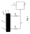
- a paper web 1 is unwound from a paper reel 3 reeled on a reeling core 2.
- the paper web 1 is guided to further processing from the reeling core.
- members 4a, 4b are placed in connection with the paper reel 3 that is being unwound, the members being utilized to measure the shape of the cross-section of the paper reel 3 that is being unwound.
- the measurement takes place in the cross-sectional plane, which is perpendicular to the central axis of the rotating movement of the reeling core.
- the members 4a and 4b are distance meters functioning on the non-contacting measurement principle, such as laser meters or microwave radars. It should be noted that this embodiment presents two members 4a, 4b as examples. There may be a larger number of them, or only one which covers a suitably wide area on the surface of the paper reel.
- the members 4a, 4b measuring the shape of the cross-section of the paper reel 3 that is being unwound are divided into two groups and positioned to measure the shape of the cross-section simultaneously from two points in the paper reel 3 that is being unwound.
- the defects generated in the reeling up of the paper reel 3 typically occur in the edge areas of the paper reel, and thus it is advantageous to place the distance measurement at least in these edge areas, e.g. within a distance of 10 cm from both ends of the paper reel 3. According to the width of the paper reel 3 it is possible to extend the measurement as far as 1500 mm from said end.
- Another alternative is to arrange a fast, scanning measurement to extend e.g. within an area of one meter from both ends of the paper reel 3 that is being unwound.
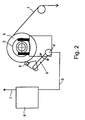
- the method according to the invention can, in addition to the non-contacting embodiment shown in Fig. 1, also be applied by means of contacting measuring method according to the apparatus embodiment shown in Fig. 2.
- the member for conducting the contacting measurement can be for example a roll 8 rotating against the surface of the paper reel 3, which roll is loaded slightly against the outer surface of the paper reel 3.
- the periodical, growing, local and temporary deviation (see Fig. 3) in the diameter of the paper reel occurs as a periodical, accelerating movement of the roll 8 i.e. as an oscillation of a particular kind.
- This can be detected for example by providing the support 9 of the roll 8 with an acceleration sensor 4' or another suitable sensor from which a signal can be conveyed to a computer 6 via a line 5.
- the roll 8 or the like can be full in width, or merely at least one pair of rolls placed on the edge areas.
- the full-width roll only detects a defect within a particular area, and if the signal in question, for example, is a signal that triggers a web change in a coating machine, the location of the defect in the roll (in the cross direction) is not actually significant, but the fact that the web change is conducted before the defect point enters the coating station thereby causing a web break.
- the aim is to conduct the web change at a normal running speed, i.e. by means of a so-called flying change.
- the necessary signals are transferred from the computer to a process control system along a line 7.
- the act of processing the measurement information as well as the detection of defects takes place either by directly monitoring the measurement signal, or by producing a frequency spectrum from the signal.
- the direct monitoring of the measurement signal is based on the recognition of the signal shape (temporal shape of the pulse, i.e. duration and amplitude), i.e. the signal shape/shapes corresponding to the defect/defects in the paper reel is/are stored in the computer 6, wherein the comparison of the measured signal arriving from the distance meters 4a, 4b takes place between said measured signal and a signal stored in the memory of the computer and corresponding to said defect in the paper reel, wherein the advantage lies in the fast and accurate reaction according to the defect type.
- the signal shape temporary shape of the pulse, i.e. duration and amplitude
- the monitoring of the frequency spectrum (hereinbelow shortly spectrum), in turn, requires information recorded from several revolutions of the paper reel 3 that is unwound, wherein the time to react to the appearing defect by means of process control is reduced.
- the advantage attained is that the defect identification accuracy is improved.
- Fig. 3 shows schematically the occurrence of the defect in the paper reel 3 in the measurement.
- the vertical axis illustrates the measured distance from the surface of the paper reel 3 to be unwound
- the horizontal axis illustrates the rotational angle of the paper reel.
- the defect in the paper reel occurs (typically at intervals of 360°) as a rapid change 8a, 8b, 8c... of small angular distance, typically under 6° (10° at the most) in the distance i.e. horizontal line 9, which otherwise remains constant (ideal situation) during the measurement period in question.
- the diameter of the paper reel 3 does not have the time to change to such an extent that it would affect the measurement result or the analysis of the same.
- the periodical occurrence of the defect becomes stronger when the rotation of the paper reel 3 proceeds, and causes a pulse that becomes stronger and corresponds to a particular change in the diameter of the paper reel (i.e. 8d nearly 1mm), and thereby in the shape of the cross-section, i.e. in the presumed circular shape (deviation in the horizontal line 9).
- the horizontal line 9 thus describes an ideal situation in which the cross-sectional shape of the paper reel is circular.
- the paper reel can, at least for the part of the outer layers contain depressions developed during the storing and handling, or the cross-section of the paper reel is for example moulded into elliptical shape during the storage.
- Such "deformations" in the cross-section occur as wide angular sector disturbances in the horizontal line 9, for example as "dents” or wave shapes.
- Such wide sector disturbances can be calculatorily filtered off, and it is obvious that a local radial change occurring inside such a wide sector disturbance area can be detected.
- the process control system recognizes a disturbance or defect in the paper reel 3 in a reliable manner, the more time the process control system has for action, i.e. for preparing itself to a possible web, for reducing the harmful effects of the possible web break, or even for avoiding the break e.g. by replacing the paper reel that is unwound by a new, full paper reel. For example during supercalendering it is possible to slow down the running speed or reduce the web tension.
- the defect is substantial, it is possible to stop the process and pass the defect point in the paper web past the further processing stage, e.g. to a pulper, and to start unwinding and processing again after the defect point has been removed.
- the act of monitoring the shape of the cross-section of the paper reel 3 can be applied also during the reeling up process in a manner described hereinbelow.
- the reeling up process it is possible to utilize the measurement information collected according to the invention as a function of the amount of paper accumulated on the reeling core of the paper reel, in other words the diameter/radius of the paper reel 3, as an aid in the measurement/monitoring according to the invention conducted during the next unwinding process of the same paper reel 3.
- the information collected in the aforementioned manner during the reeling up process can be used when estimating the probability for that whether the paper reel in question contains reeling defects and further in which point of the unwinding process i.e.
- defects can occur in the paper reel in the reeling up process either in the surface layer/layers reeled at a given time or deeper in the paper reel (i.e. caused by the movement of slack layers with respect to each other), and further, because defects can occur in connection with the handling and/or storing of the full paper reel, taking place after the reeling up, the measurements and monitoring conducted during the unwinding are, however, the primary methods when the aim is to utilize the paper web unwound from the paper reel as efficiently as possible in the further processing stages.
- the measurement of the shape of the cross-section of the paper reel can be implemented either by means of distance meters, such as a laser meter or a microwave radar, functioning on the non-contacting principle, or by means of a contacting measurement method.
- the signal obtained from these measurement devices can naturally also be used for other kind of monitoring of the condition of the unwinding device and/or for monitoring the behaviour of the paper reel that is being unwound by conducting an analysis of the measurement signals in a suitable manner.
- a failure occurring in the bearing arrangement enabling the rotation of the reeling core 2 can be detected by measurements taken from the surface of the unwound paper reel 3, by means of vibrations caused by said bearing arrangement failure in said reeling core and further in said unwound paper reel.
- the vibrations detected on the surface of the paper reel can also be transmitted from other failured parts which are located elsewhere in the unwinding apparatus, either in the vicinity of the paper reel 3 or further apart from said paper reel.
- Such failured parts can be for example different supporting rolls or the bearing arrangements of the same, or the bearing arrangements and/or drives of other rotating or linearly moving members.
- vibrations caused by a failure in the bearing arrangement which typically are indicated at higher frequencies than the signals caused by the reeling defect of the paper web.
Landscapes
- Controlling Rewinding, Feeding, Winding, Or Abnormalities Of Webs (AREA)
- Replacement Of Web Rolls (AREA)
- Unwinding Webs (AREA)
- Paper (AREA)
Claims (22)
- Verfahren im kontinuierlichen Abwickeln einer Papierbahn, in welchem ein auf einem Wickelkern (2) oder ähnlichem aufgewickelter Papierwickel (3) durch Rotieren desselben abgewickelt wird, um die Papierbahn (1) zu einem weiteren Verarbeitungsschritt zu führen,
dadurch gekennzeichnet, dass die Form der äußeren Oberfläche des abgewickelten Papierwickels (3) gemessen wird, vorteilhaft in der Querschnittsebene des Papierwickels. - Verfahren nach Anspruch 1,
dadurch gekennzeichnet, dass die Form der äußeren Oberfläche des Papierwickels (3) von wenigstens zwei Stellen gemessen wird. - Verfahren nach Anspruch 1 oder 2,
dadurch gekennzeichnet, dass die Form der äußeren Oberfläche des Papierwickels (3) von wenigstens zwei Punkten gemessen wird, welche an den Enden des Papierwickels (3) positioniert sind oder sich bis zu höchstens 1500 mm über die Enden des Papierwickels (3) erstrecken. - Verfahren nach einem der Ansprüche 1 bis 3,
dadurch gekennzeichnet, dass die in der Form der äußeren Oberfläche auftretenden lokalen radialen Änderungen (8a, 8b...) beobachtet bzw. überwacht werden. - Verfahren nach Anspruch 1 oder 4,
dadurch gekennzeichnet, dass Änderungen (8a, 8b, 8c...) beobachtet bzw, überwacht werden, deren Sektorwinkel (ϕ) typischerweise kleiner als 6°, aber in etwa unter 10° ist. - Verfahren nach Anspruch 1 oder 5,
dadurch gekennzeichnet, dass die Messung mit dem Ziel durchgeführt wird, das Wachsen einer Seriet = Zeit,i= 1, 2, 3, ...Δr = lokale radiale Änderung in dem "Referenzwert", undα = Beobachtungswinkel von Δri ist, worin damit - Verfahren nach einem der Ansprüche 1 bis 5,
dadurch gekennzeichnet, dass das Verfahren während des Aufwickelns des Papierwickels (3) angewandt wird, und dass bei der Aufwicklung wird die, als eine Funktion der Menge an auf dem Wickelkern (2) des Papierwickels (3) akkumulierten Papiers, d. h. des Durchmessers/Radius des Papierwickels (3), gesammelte Information in der Messung/Beobachtung gemäß der Erfindung genutzt wird, welche während des nächsten Abwickelprozesses derselben Papierwickeleinheit (3) durchgeführt wird. - Verfahren nach einem der Ansprüche 1 bis 7,
dadurch gekennzeichnet, dass nach Entdeckung der in der Form der äußeren Oberfläche auftretenden lokalen radialen Änderung (8a, 8b), Steuerfunktionen ausgeführt werden, welche mit den Tätigkeiten des Abwickelprozesses verbunden sind. - Verfahren nach einem der Ansprüche 1 bis 8,
dadurch gekennzeichnet, dass ein Wechsel des abzuwickelnden Papierwickels (3), vorzugsweise eine fliegender Wechsel, ausgeführt wird. - Verfahren nach einem der Ansprüche 1 bis 8,
dadurch gekennzeichnet, dass die Laufgeschwindigkeit der Papierbahn (1) reduziert wird und/oder die Bahnspannung reduziert wird. - Verfahren nach einem der Ansprüche 1 bis 8,
dadurch gekennzeichnet, dass ein Teil der Papierbahn (1) an dem folgenden Verarbeitungsschritt vorbeigerührt wird. - Vorrichtung im kontinuierlichen Abwickeln eines Papierwickels, in welcher ein voller, auf einem Wickelkern oder ähnlichem aufgewickelter Papierwickel eingerichtet ist, um durch Rotieren desselben abgewickelt zu werden, um die Papierbahn zur weiteren Verarbeitung zu führen,
dadurch gekennzeichnet, dass die Vorrichtung Teile (4a, 4b; 8, 4') zum Messen der Form der äußeren Oberfläche des Papierwickels (3) umfaßt, vorteilhaft in der Querschnittsebene des Papierwickels. - Vorrichtung nach Anspruch 12,
dadurch gekennzeichnet, dass die Teile (4a, 4b) eingerichtet sind, um die Form der äußeren Oberfläche des Papierwickels (3) in einer berührungslosen Weise zu messen. - Vorrichtung nach Anspruch 12,
dadurch gekennzeichnet, dass die Teile (8,4') eingerichtet sind, um die Form der äußeren Oberfläche des Papierwickels (3) in einer berührenden Weise zu messen. - Vorrichtung nach Anspruch 12 oder 13,
dadurch gekennzeichnet, dass die Teile (4a, 4b) in zwei Gruppen aufgeteilt sind, von welchen die erste Gruppe (4a) die Form des Querschnitts des Papierwickels (3) in der Nähe des ersten Endes des Papierwickels (3) misst und die zweite Gruppe (4b) in der Nähe des zweiten Endes. - Vorrichtung nach einem der Ansprüche 12, 13 oder 15,
dadurch gekennzeichnet, dass die Teile (4a, 4b) Lasermessgeräte sind. - Vorrichtung nach einem der Ansprüche 12, 13 oder 15,
dadurch gekennzeichnet, dass die Teile (4a, 4b) Mikrowellenradare sind. - Vorrichtung nach Anspruch 12 oder 14,
dadurch gekennzeichnet, dass das Teil, welches die äußere Oberfläche des Papierwickels (3) berührt eine Walze (8) oder ähnliches ist, und dass ein Teil (4') eingerichtet ist, um die Walze (8) derart zu tragen, dass die lokale Änderung in der radialen Richtung, welche von dem Papierwickel (3) zu der Walze (8) übertragen wird entdeckt werden kann. - Vorrichtung nach Anspruch 18,
dadurch gekennzeichnet, dass das Teil (4') ein Beschleunigungssensor ist. - Vorrichtung nach einem der Ansprüche 12 bis 19,
dadurch gekennzeichnet, dass Teile (4a, 4b, 4') mit einem Computer (6) oder ähnlichem verbunden sind, in welchem eine kontinuierliche Analyse der Meßergebnisse durchführbar ist, und von welchem Information von den Ergebnissen der Analyse zu dem Steuersystem des Prozesses weitergebbar ist. - Vorrichtung nach Anspruch 20,
dadurch gekennzeichnet, dass die Analyse der Meßergebnisse eingerichtet ist Funktionen zur Überwachung bzw. Beobachtung des Zustands der Abwickelvorrichtung gemäß dem Vibrationen-Meßprinzip zu enthalten. - Vorrichtung nach Anspruch 20 oder 21,
dadurch gekennzeichnet, dass die Analyse der Meßergebnisse eingerichtet ist Funktionen zur Überwachung bzw. Beobachtung der Betriebssicherheit der Abwickelvorrichtung zu enthalten.
Applications Claiming Priority (3)
| Application Number | Priority Date | Filing Date | Title |
|---|---|---|---|
| FI990701 | 1999-03-30 | ||
| FI990701A FI105803B (fi) | 1999-03-30 | 1999-03-30 | Menetelmä ja laitteisto paperirullan jatkuvatoimisessa aukirullauksessa |
| PCT/FI2000/000251 WO2000061482A1 (en) | 1999-03-30 | 2000-03-27 | Method and device in continuously operated unwinding of a paper reel |
Publications (2)
| Publication Number | Publication Date |
|---|---|
| EP1204582A1 EP1204582A1 (de) | 2002-05-15 |
| EP1204582B1 true EP1204582B1 (de) | 2003-05-07 |
Family
ID=8554314
Family Applications (1)
| Application Number | Title | Priority Date | Filing Date |
|---|---|---|---|
| EP00914219A Expired - Lifetime EP1204582B1 (de) | 1999-03-30 | 2000-03-27 | Verfahren und vorrichtung zum kontinuierlich betriebenen abwickeln einer papierrolle |
Country Status (8)
| Country | Link |
|---|---|
| US (1) | US6685133B1 (de) |
| EP (1) | EP1204582B1 (de) |
| AT (1) | ATE239660T1 (de) |
| AU (1) | AU3562300A (de) |
| CA (1) | CA2368935A1 (de) |
| DE (1) | DE60002582T2 (de) |
| FI (1) | FI105803B (de) |
| WO (1) | WO2000061482A1 (de) |
Families Citing this family (10)
| Publication number | Priority date | Publication date | Assignee | Title |
|---|---|---|---|---|
| US6719240B2 (en) | 2001-11-13 | 2004-04-13 | Kimberly-Clark Worldwide, Inc. | System and method for unwinding tissue webs |
| US6722606B2 (en) | 2001-11-13 | 2004-04-20 | Kimberly-Clark Worldwide, Inc. | System and method for simultaneously unwinding multiple rolls of material |
| US6820837B2 (en) | 2002-12-20 | 2004-11-23 | Kimberly-Clark Worldwide, Inc. | Unwind system with flying-splice roll changing |
| US7660654B2 (en) * | 2004-12-13 | 2010-02-09 | Ford Global Technologies, Llc | System for dynamically determining vehicle rear/trunk loading for use in a vehicle control system |
| DE102005002030B4 (de) * | 2005-01-15 | 2007-08-30 | Koenig & Bauer Aktiengesellschaft | Rollenwechsler zur Zuführung einer Materialbahn |
| FI119980B (fi) * | 2006-11-13 | 2009-05-29 | Metso Paper Inc | Menetelmä kuiturainakoneen rullaimen yhteydessä |
| DE102008050813B4 (de) * | 2008-10-08 | 2020-08-20 | Manroland Goss Web Systems Gmbh | Vorrichtung zum drehenden Antreiben einer Materialbahnrolle |
| CN201693589U (zh) * | 2010-01-30 | 2011-01-05 | 宏恒胜电子科技(淮安)有限公司 | 裁切装置 |
| US10150631B1 (en) * | 2017-09-22 | 2018-12-11 | Kabushiki Kaisha Toshiba | Sheet conveyance apparatus and sheet conveyance method |
| SE547661C2 (en) * | 2022-06-27 | 2025-11-04 | Valmet Oy | Method and system for monitoring the performance of a winding spool in the reel section of a paper machine |
Family Cites Families (13)
| Publication number | Priority date | Publication date | Assignee | Title |
|---|---|---|---|---|
| US1149018A (en) * | 1914-07-22 | 1915-08-03 | Charles Francis | Paper-feed-controlling apparatus. |
| US3427723A (en) * | 1967-05-26 | 1969-02-18 | Oxford Paper Co | Roll profiler |
| CA925286A (en) * | 1969-07-11 | 1973-05-01 | Canadian International Paper Company | Apparatus for detecting surface variations |
| US3869770A (en) * | 1973-08-10 | 1975-03-11 | Deering Milliken Res Corp | Tight warp detector |
| GB1474191A (en) * | 1974-01-21 | 1977-05-18 | Nat Res Dev | Measurement of surface roughness |
| JPS56151119A (en) * | 1980-04-10 | 1981-11-24 | Davy Loewy Ltd | Winder for metallic strip material |
| SE441520B (sv) * | 1984-03-07 | 1985-10-14 | Tetra Pak Int | Anordning for avkenning av materialtjockleken i en rulle av banformigt material |
| JPH0455000Y2 (de) * | 1987-11-02 | 1992-12-24 | ||
| DE4037671A1 (de) * | 1990-11-27 | 1992-06-04 | Sundwiger Eisen Maschinen | Positioniervorrichtung fuer auf eine haspeltrommel aufzusteckende bunde, insbesondere aus metallband |
| JPH05508375A (ja) * | 1991-05-03 | 1993-11-25 | イーストマン・コダック・カンパニー | ウェブの巻付け制御方法 |
| US5535627A (en) * | 1994-01-14 | 1996-07-16 | The Board Of Regents Of Oklahoma State University | Roll structure acoustic gage and method |
| DE19508861A1 (de) * | 1995-03-11 | 1996-09-12 | Zeiss Carl Fa | Koordinatenmeßgerät mit einer Einrichtung für die Rauheitsmessung |
| FI106446B (fi) * | 1998-02-04 | 2001-02-15 | Valmet Corp | Menetelmä rainan rullauksessa |
-
1999
- 1999-03-30 FI FI990701A patent/FI105803B/fi active
-
2000
- 2000-03-27 WO PCT/FI2000/000251 patent/WO2000061482A1/en not_active Ceased
- 2000-03-27 US US09/937,883 patent/US6685133B1/en not_active Expired - Fee Related
- 2000-03-27 AU AU35623/00A patent/AU3562300A/en not_active Abandoned
- 2000-03-27 DE DE60002582T patent/DE60002582T2/de not_active Expired - Fee Related
- 2000-03-27 CA CA002368935A patent/CA2368935A1/en not_active Abandoned
- 2000-03-27 AT AT00914219T patent/ATE239660T1/de not_active IP Right Cessation
- 2000-03-27 EP EP00914219A patent/EP1204582B1/de not_active Expired - Lifetime
Also Published As
| Publication number | Publication date |
|---|---|
| FI105803B (fi) | 2000-10-13 |
| EP1204582A1 (de) | 2002-05-15 |
| US6685133B1 (en) | 2004-02-03 |
| WO2000061482A1 (en) | 2000-10-19 |
| FI990701A0 (fi) | 1999-03-30 |
| CA2368935A1 (en) | 2000-10-19 |
| DE60002582T2 (de) | 2003-11-20 |
| AU3562300A (en) | 2000-11-14 |
| DE60002582D1 (de) | 2003-06-12 |
| ATE239660T1 (de) | 2003-05-15 |
Similar Documents
| Publication | Publication Date | Title |
|---|---|---|
| US6685133B1 (en) | Method and device in continuously operated unwinding of a paper reel | |
| US5949550A (en) | Method and apparatus for detecting defects in a moving web | |
| FI108635B (fi) | Menetelmä rullanmuodostuksen laadun määrittämiseksi ja rullanmuodostuksen ohjaamiseksi | |
| FI117171B (fi) | Menetelmä ja laitteisto rullauksen hallitsemiseksi | |
| US6598529B2 (en) | Method and device for detecting faults during transport of a web | |
| EP3576911B1 (de) | Verfahren zur überprüfung des korrekten betriebs einer vorschneide- und umspulmaschine | |
| US20080017341A1 (en) | Reeling Method and System as Well as an Measuring Apparatus | |
| US11008190B2 (en) | Method, system and a computer program product for condition monitoring of a fiber web or paper finishing machine | |
| EP1198701B1 (de) | Verfahren zur überwachung von geräten | |
| CN114906566B (zh) | 一种断带检测装置及方法 | |
| EP1082260B1 (de) | Verfahren und vorrichtung zum abwickeln | |
| US5769353A (en) | Method of initiating the premature replacement of a roll of material | |
| CN107780285B (zh) | 用于运行用于制造和/或加工材料幅的机器的方法 | |
| WO2010028867A1 (en) | Slitter-winder assembly having a sensor system | |
| CA2501969C (en) | Method for determining the modulus of elasticity of paper | |
| FI119980B (fi) | Menetelmä kuiturainakoneen rullaimen yhteydessä | |
| US11801612B2 (en) | Device for determining and storing eccentricity of customer roll within a slitter winder and using for unwinding control | |
| WO2003031297A1 (en) | Method and measuring equipment for determining angular speed difference | |
| JP3352145B2 (ja) | 印刷機の紙切れ検出装置 | |
| FI121113B (fi) | Rullausmenetelmä ja -järjestelmä | |
| JP4025840B2 (ja) | 紙等のリール巻き付き検出方法 | |
| KR100343118B1 (ko) | 장력신호의 주파수 해석을 이용한 롤 형상 이상진단 장치및 방법 | |
| KR101203645B1 (ko) | 코일 오프너설비의 전도방지장치 | |
| FI122277B (fi) | Menetelmä paperi- tai kartonkikoneen radanhallinnassa | |
| Stevens et al. | Winding and reeling quality and productivity optimisation |
Legal Events
| Date | Code | Title | Description |
|---|---|---|---|
| PUAI | Public reference made under article 153(3) epc to a published international application that has entered the european phase |
Free format text: ORIGINAL CODE: 0009012 |
|
| 17P | Request for examination filed |
Effective date: 20010926 |
|
| AK | Designated contracting states |
Kind code of ref document: A1 Designated state(s): AT BE CH CY DE DK ES FI FR GB GR IE IT LI LU MC NL PT SE |
|
| GRAH | Despatch of communication of intention to grant a patent |
Free format text: ORIGINAL CODE: EPIDOS IGRA |
|
| GRAH | Despatch of communication of intention to grant a patent |
Free format text: ORIGINAL CODE: EPIDOS IGRA |
|
| GRAA | (expected) grant |
Free format text: ORIGINAL CODE: 0009210 |
|
| AK | Designated contracting states |
Designated state(s): AT DE FR GB IT SE |
|
| PG25 | Lapsed in a contracting state [announced via postgrant information from national office to epo] |
Ref country code: IT Free format text: LAPSE BECAUSE OF FAILURE TO SUBMIT A TRANSLATION OF THE DESCRIPTION OR TO PAY THE FEE WITHIN THE PRESCRIBED TIME-LIMIT;WARNING: LAPSES OF ITALIAN PATENTS WITH EFFECTIVE DATE BEFORE 2007 MAY HAVE OCCURRED AT ANY TIME BEFORE 2007. THE CORRECT EFFECTIVE DATE MAY BE DIFFERENT FROM THE ONE RECORDED. Effective date: 20030507 |
|
| REG | Reference to a national code |
Ref country code: GB Ref legal event code: FG4D |
|
| REG | Reference to a national code |
Ref country code: IE Ref legal event code: FG4D |
|
| REF | Corresponds to: |
Ref document number: 60002582 Country of ref document: DE Date of ref document: 20030612 Kind code of ref document: P |
|
| REG | Reference to a national code |
Ref country code: SE Ref legal event code: TRGR |
|
| ET | Fr: translation filed | ||
| PLBE | No opposition filed within time limit |
Free format text: ORIGINAL CODE: 0009261 |
|
| STAA | Information on the status of an ep patent application or granted ep patent |
Free format text: STATUS: NO OPPOSITION FILED WITHIN TIME LIMIT |
|
| 26N | No opposition filed |
Effective date: 20040210 |
|
| REG | Reference to a national code |
Ref country code: IE Ref legal event code: MM4A |
|
| PGFP | Annual fee paid to national office [announced via postgrant information from national office to epo] |
Ref country code: FR Payment date: 20060313 Year of fee payment: 7 |
|
| PGFP | Annual fee paid to national office [announced via postgrant information from national office to epo] |
Ref country code: GB Payment date: 20060322 Year of fee payment: 7 |
|
| PG25 | Lapsed in a contracting state [announced via postgrant information from national office to epo] |
Ref country code: SE Free format text: LAPSE BECAUSE OF NON-PAYMENT OF DUE FEES Effective date: 20070328 |
|
| EUG | Se: european patent has lapsed | ||
| GBPC | Gb: european patent ceased through non-payment of renewal fee |
Effective date: 20070327 |
|
| REG | Reference to a national code |
Ref country code: FR Ref legal event code: ST Effective date: 20071130 |
|
| PGFP | Annual fee paid to national office [announced via postgrant information from national office to epo] |
Ref country code: SE Payment date: 20060314 Year of fee payment: 7 |
|
| PG25 | Lapsed in a contracting state [announced via postgrant information from national office to epo] |
Ref country code: GB Free format text: LAPSE BECAUSE OF NON-PAYMENT OF DUE FEES Effective date: 20070327 |
|
| PG25 | Lapsed in a contracting state [announced via postgrant information from national office to epo] |
Ref country code: FR Free format text: LAPSE BECAUSE OF NON-PAYMENT OF DUE FEES Effective date: 20070402 |
|
| PGFP | Annual fee paid to national office [announced via postgrant information from national office to epo] |
Ref country code: AT Payment date: 20090317 Year of fee payment: 10 |
|
| PGFP | Annual fee paid to national office [announced via postgrant information from national office to epo] |
Ref country code: DE Payment date: 20090320 Year of fee payment: 10 |
|
| PG25 | Lapsed in a contracting state [announced via postgrant information from national office to epo] |
Ref country code: AT Free format text: LAPSE BECAUSE OF NON-PAYMENT OF DUE FEES Effective date: 20100327 |
|
| PG25 | Lapsed in a contracting state [announced via postgrant information from national office to epo] |
Ref country code: DE Free format text: LAPSE BECAUSE OF NON-PAYMENT OF DUE FEES Effective date: 20101001 |