EP1204824B1 - Drehtischmaschine zum behandeln von hohlkörpern die ein verbessertes druckverteilungsnetz aufweisst - Google Patents
Drehtischmaschine zum behandeln von hohlkörpern die ein verbessertes druckverteilungsnetz aufweisst Download PDFInfo
- Publication number
- EP1204824B1 EP1204824B1 EP00915226A EP00915226A EP1204824B1 EP 1204824 B1 EP1204824 B1 EP 1204824B1 EP 00915226 A EP00915226 A EP 00915226A EP 00915226 A EP00915226 A EP 00915226A EP 1204824 B1 EP1204824 B1 EP 1204824B1
- Authority
- EP
- European Patent Office
- Prior art keywords
- orifices
- series
- same
- pressure
- machine
- Prior art date
- Legal status (The legal status is an assumption and is not a legal conclusion. Google has not performed a legal analysis and makes no representation as to the accuracy of the status listed.)
- Expired - Lifetime
Links
Images




Classifications
-
- B—PERFORMING OPERATIONS; TRANSPORTING
- B29—WORKING OF PLASTICS; WORKING OF SUBSTANCES IN A PLASTIC STATE IN GENERAL
- B29C—SHAPING OR JOINING OF PLASTICS; SHAPING OF MATERIAL IN A PLASTIC STATE, NOT OTHERWISE PROVIDED FOR; AFTER-TREATMENT OF THE SHAPED PRODUCTS, e.g. REPAIRING
- B29C49/00—Blow-moulding, i.e. blowing a preform or parison to a desired shape within a mould; Apparatus therefor
- B29C49/28—Blow-moulding apparatus
- B29C49/30—Blow-moulding apparatus having movable moulds or mould parts
- B29C49/36—Blow-moulding apparatus having movable moulds or mould parts rotatable about one axis
-
- B—PERFORMING OPERATIONS; TRANSPORTING
- B29—WORKING OF PLASTICS; WORKING OF SUBSTANCES IN A PLASTIC STATE IN GENERAL
- B29C—SHAPING OR JOINING OF PLASTICS; SHAPING OF MATERIAL IN A PLASTIC STATE, NOT OTHERWISE PROVIDED FOR; AFTER-TREATMENT OF THE SHAPED PRODUCTS, e.g. REPAIRING
- B29C51/00—Shaping by thermoforming, i.e. shaping sheets or sheet like preforms after heating, e.g. shaping sheets in matched moulds or by deep-drawing; Apparatus therefor
- B29C51/18—Thermoforming apparatus
- B29C51/20—Thermoforming apparatus having movable moulds or mould parts
- B29C51/22—Thermoforming apparatus having movable moulds or mould parts rotatable about an axis
-
- F—MECHANICAL ENGINEERING; LIGHTING; HEATING; WEAPONS; BLASTING
- F16—ENGINEERING ELEMENTS AND UNITS; GENERAL MEASURES FOR PRODUCING AND MAINTAINING EFFECTIVE FUNCTIONING OF MACHINES OR INSTALLATIONS; THERMAL INSULATION IN GENERAL
- F16K—VALVES; TAPS; COCKS; ACTUATING-FLOATS; DEVICES FOR VENTING OR AERATING
- F16K11/00—Multiple-way valves, e.g. mixing valves; Pipe fittings incorporating such valves
- F16K11/02—Multiple-way valves, e.g. mixing valves; Pipe fittings incorporating such valves with all movable sealing faces moving as one unit
- F16K11/06—Multiple-way valves, e.g. mixing valves; Pipe fittings incorporating such valves with all movable sealing faces moving as one unit comprising only sliding valves, i.e. sliding closure elements
- F16K11/072—Multiple-way valves, e.g. mixing valves; Pipe fittings incorporating such valves with all movable sealing faces moving as one unit comprising only sliding valves, i.e. sliding closure elements with pivoted closure members
- F16K11/074—Multiple-way valves, e.g. mixing valves; Pipe fittings incorporating such valves with all movable sealing faces moving as one unit comprising only sliding valves, i.e. sliding closure elements with pivoted closure members with flat sealing faces
-
- B—PERFORMING OPERATIONS; TRANSPORTING
- B29—WORKING OF PLASTICS; WORKING OF SUBSTANCES IN A PLASTIC STATE IN GENERAL
- B29C—SHAPING OR JOINING OF PLASTICS; SHAPING OF MATERIAL IN A PLASTIC STATE, NOT OTHERWISE PROVIDED FOR; AFTER-TREATMENT OF THE SHAPED PRODUCTS, e.g. REPAIRING
- B29C2791/00—Shaping characteristics in general
- B29C2791/004—Shaping under special conditions
- B29C2791/006—Using vacuum
-
- B—PERFORMING OPERATIONS; TRANSPORTING
- B29—WORKING OF PLASTICS; WORKING OF SUBSTANCES IN A PLASTIC STATE IN GENERAL
- B29C—SHAPING OR JOINING OF PLASTICS; SHAPING OF MATERIAL IN A PLASTIC STATE, NOT OTHERWISE PROVIDED FOR; AFTER-TREATMENT OF THE SHAPED PRODUCTS, e.g. REPAIRING
- B29C59/00—Surface shaping of articles, e.g. embossing; Apparatus therefor
- B29C59/02—Surface shaping of articles, e.g. embossing; Apparatus therefor by mechanical means, e.g. pressing
- B29C59/04—Surface shaping of articles, e.g. embossing; Apparatus therefor by mechanical means, e.g. pressing using rollers or endless belts
- B29C59/043—Surface shaping of articles, e.g. embossing; Apparatus therefor by mechanical means, e.g. pressing using rollers or endless belts for profiled articles
-
- Y—GENERAL TAGGING OF NEW TECHNOLOGICAL DEVELOPMENTS; GENERAL TAGGING OF CROSS-SECTIONAL TECHNOLOGIES SPANNING OVER SEVERAL SECTIONS OF THE IPC; TECHNICAL SUBJECTS COVERED BY FORMER USPC CROSS-REFERENCE ART COLLECTIONS [XRACs] AND DIGESTS
- Y10—TECHNICAL SUBJECTS COVERED BY FORMER USPC
- Y10T—TECHNICAL SUBJECTS COVERED BY FORMER US CLASSIFICATION
- Y10T137/00—Fluid handling
- Y10T137/8593—Systems
- Y10T137/86493—Multi-way valve unit
-
- Y—GENERAL TAGGING OF NEW TECHNOLOGICAL DEVELOPMENTS; GENERAL TAGGING OF CROSS-SECTIONAL TECHNOLOGIES SPANNING OVER SEVERAL SECTIONS OF THE IPC; TECHNICAL SUBJECTS COVERED BY FORMER USPC CROSS-REFERENCE ART COLLECTIONS [XRACs] AND DIGESTS
- Y10—TECHNICAL SUBJECTS COVERED BY FORMER USPC
- Y10T—TECHNICAL SUBJECTS COVERED BY FORMER US CLASSIFICATION
- Y10T137/00—Fluid handling
- Y10T137/8593—Systems
- Y10T137/86493—Multi-way valve unit
- Y10T137/86558—Plural noncommunicating flow paths
-
- Y—GENERAL TAGGING OF NEW TECHNOLOGICAL DEVELOPMENTS; GENERAL TAGGING OF CROSS-SECTIONAL TECHNOLOGIES SPANNING OVER SEVERAL SECTIONS OF THE IPC; TECHNICAL SUBJECTS COVERED BY FORMER USPC CROSS-REFERENCE ART COLLECTIONS [XRACs] AND DIGESTS
- Y10—TECHNICAL SUBJECTS COVERED BY FORMER USPC
- Y10T—TECHNICAL SUBJECTS COVERED BY FORMER US CLASSIFICATION
- Y10T137/00—Fluid handling
- Y10T137/8593—Systems
- Y10T137/86493—Multi-way valve unit
- Y10T137/86831—Selective opening of plural ports
Definitions
- the invention relates to the field of carousel machines for treatment of hollow bodies, of the type comprising several stations for identical treatment each intended to support at least one hollow body, and of the type in which, for at least one stage of the treatment, we put the treatment station in communication with a pressure source via a sealed swivel fitting, such than the machine described in document FR -A- 2 291 919.
- each processing on the carousel is at a particular stage of advancement of the processing, in particular within the framework of the stages during which produce continuous variations of the parameters that characterize the progress of treatment.
- the number of stations is large, it may be that two stations consecutive, therefore close to each other, are in progress performing the same step, but at different stages of advancement of this step. The two stations are then at pressure levels different.
- a machine blowing plastic containers.
- This machine has a fluid pressure distributor which is provided with a fixed crown in which are arranged, on a transverse face, two grooves concentric annulars of different diameters. Each of the two gorges is divided into a number of sections which are connected each pressure sources of different levels, possibly even the atmosphere.
- the machine described is only intended to operate with a single treatment station.
- the distributor also includes a rotary member which is provided with two communication orifices of which each is intended to circulate opposite one of the gorges, opposite consecutively with the different sections of the corresponding groove.
- the dispenser described makes it possible to put the treatment station in communication with a first source of high pressure air, i.e. about 6 bars, with a second source of low pressure air, i.e. about 3 bars, or with the atmosphere.
- the machine described does not provide a solution for setting multiple positions in the case where it is desired that, at each instant, at most one station is in communication with a source of given pressure.
- the section considered throat has an angular extent corresponding to the duration of the stage considered.
- the object of the invention is therefore to propose a machine which can include a significant number of positions, while ensuring that a pressure source is in communication, at a given time, only at more at a treatment center.
- the invention provides a machine of the type described previously, characterized in that, for said step, the machine has at least two independent pressure sources and equivalent, in that the positions are divided into as many groups as the machine has sources, and in that the distribution means are such that each source is associated with a separate group.
- the invention also provides a rotary distributor for a machine with a hollow body treatment carousel, the machine comprising several Identical treatment stations each intended to support the minus a hollow body, of the type in which the distributor has two coaxial rings, one fixed and the other rotary, which are in contact one with the other in a sealed manner by contact faces facing each other, type in which the rotary crown has holes for communication which are each intended to be connected to a station and which open into the contact face of the rotary crown, and of the type wherein the fixed crown comprises at least one light which is intended to be connected to a pressure source of the machine and which opens into the contact face of the fixed crown so as to find on the trajectory of the holes of the rotary crown, so a station is put in communication with the pressure source when the corresponding hole is located opposite the light, characterized in that the holes in the rotating ring are divided into at least two series, in that the orifices of the same series follow the same trajectory while the orifices of two different series follow trajectories different, in that
- FIG. 1 Illustrated in Figure 1 very schematically an example for making a machine in accordance with the teachings of the invention.
- the machine 10 illustrated is intended to perform a treatment on hollow bodies, the treatment consisting in depositing, using low pressure plasma, a coating on hollow bodies.
- the bodies hollow in question are for example containers such as bottles or bottles, and they can be made of a plastic material such than polyethylene terephthalate.
- the use of low pressure plasma requires operating in a reaction cavity in which the absolute pressure is preferably less than a millibar.
- the machine is intended for allow the processing of several thousand, even several tens of thousands of hollow bodies per hour.
- the machine 10 comprises several treatment stations 12, 13, in this case twenty stations which are carried by a carousel 16 rotated about an axis X-X. All posts 12, 13 are identical and are arranged in a circle around the X-X axis. They are each intended to receive at least one hollow body so that it undergoes the treatment planned during the rotation of the carousel 16.
- the processing station 12, 13 supports several hollow bodies, either inside a single reaction cavity, i.e. inside several cavities reaction.
- the machine is intended to implement a deposit treatment in three main stages: a first stage of pumping, a second pumping step, and a deposition step.
- the two pumping steps are intended to establish in the room reaction of the post considered a sufficient vacuum to allow the creation of a plasma.
- the first pumping step is intended to create a first vacuum level in the cavity, for example by falling to a pressure absolute of the order of fifty millibars.
- the second stage of pumping is for example intended to reach an absolute level of pressure of the order of 0.1 millibars.
- each stage of the treatment takes place while the post considered moves within a determined angular sector around the X-X axis.
- the stations For the different stages of processing, the stations must therefore be put in communication with pumps. However, the weight and volume of pumps prevent them from being loaded onto the carousel 16.
- the pumps are therefore fixed and they are intended to be connected to the treatment 12, 13 by means of a rotary union 18.
- the machine 10 is designed so that posts 12, 13 are divided into two groups, and, for the same pumping step, it has two pumps independent and equivalent, the two groups of positions being differentiated according to that of the two pumps to which their posts are linked during the stage in question.
- the machine is designed to that two sets in the same group cannot communicate simultaneously with the pressure source corresponding to this group.
- the distribution means can, at a given moment, put two positions of two different groups in communication with their sources respective partners.
- the positions 12, 13 are distributed alternately in two groups which one will arbitrarily qualify as even positions 12 and odd positions 13, a group position being therefore inserted between two stations of the other group.
- the first pumping step is therefore ensured, for the group of even stations 12, by a first pump A1, and, for the group of stations odd 13, by a second pump A2.
- the two pumps associated with the same stage of treatment are independent of each other. They are also equivalent in that they ensure the same pressure levels in the stations, whatever regardless of which group the position belongs to.
- the deposition step is ensured with a single pump C which is brought to be connected to each of the positions. It will be noted that this single pump C is brought to be connected to every moment, at several stations.
- the invention can be implemented in different ways.
- the waterproof swivel fitting is a simple two-way fitting channels for connecting two fixed fluid circuits, in this case the pumps A1 and A2, with two fluid circuits on board the carousel, know the two groups of positions.
- Such a connection comprises for example two coaxial rings each provided with two continuous annular grooves, each of the grooves of a crown being opposite a groove of the other crown for thus form two annular fluid transfer spaces of a crown towards the other.
- the two annular spaces are of course connected respectively to the two pumps A1 and A2 via the fixed crown.
- the means distribution also include, at the level of each station, individual valves arranged in a pipe connecting each station to the corresponding annular space of the swivel joint. Each of these valves is then ordered in good time to open or close the communication of the post in question with the corresponding space.
- the valves can be solenoid valves or valves mechanical controlled by fixed cams arranged around the carousel.
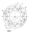
- the machine 10 has an improved rotary distributor illustrated more particularly in Figures 2 to 4.
- the swivel valve 18 does not only have the function of connecting a fixed fluid circuit to a fluid circuit on board a rotating carousel. It also has the function to determine at what moments of the rotational movement of the carousel a treatment station given on the carousel is in communication with a pump given.
- the distributor 18 has two annular rings, one fixed 20 and the other rotary 22.
- the two rings are coaxial along the axis X-X of rotation of the carousel 16, this axis preferably being vertical, and they are stacked axially one above the other.
- the rotating crown 22, which rotates with the carousel 16 is arranged above of the fixed crown so that the two crowns are in bearing against one another by transverse contact faces 24, 26 annular and perpendicular to the X-X axis.
- the rotating ring 22 is pierced with a series of orifices 28, 29 which pass axially through it partly to open on the one hand into the lower contact face 26 and on the other hand in an upper face 30.
- Each of the orifices 28, 29, which in this case are the number of twenty, is intended to be connected to one of the treatment stations by means of a pipe 32 which is tightly fixed on the upper face 30.
- the orifices are divided into two series.
- a first series of orifices 28 is arranged according to a large diameter circle while the second series of orifices 29 is arranged on a small diameter circle.
- the orifices of a same series are evenly distributed angularly, in the occurrence every 36 degrees.
- the two series of orifices have the same number of holes and they are offset angularly from each other so that, all series combined, there is an orifice every 18 degrees, which corresponds to the spacing angle of the two posts on the carousel.
- all the orifices of the same series correspond to positions in the same group.
- all the stations in the same group i.e. all stations associated with the same pump, are supplied by orifices of a same series.
- the posts of the same group can be supplied by ports belonging to two series distinct, i.e. for example a series of orifices arranged according to circles of different diameter.
- the fixed crown 20 is provided, on its contact face 22, with two series of lights in an arc.
- a first series of lights 34, 36, 38 is arranged on the same large diameter circle as the orifices pairs 28 while the second series of lights 35, 37, 39 is arranged on the same circle of small diameter as the odd holes 29.
- the lights 34, 35 are respectively connected to the pumps A1 and A2 used for the first pumping step.
- Lights 36, 37 are respectively connected to pumps B1 and B2 used for the second pumping step.
- the lights 38, 39 are on the contrary both connected to the pump C which is used for the deposition step.
- Each of the lights 34, 35, 36, 37, 38, 39 is connected to the pump associated via the corresponding holes 40 which open out in the lower face 42 of the fixed crown 20 and on which are connected conduits (not shown).
- the two lights that correspond to the same processing step and which belong to two different series are arranged on the same angular sector.
- two lights of the same series are separated one of the other by an angular sector ⁇ such that an orifice cannot be simultaneously opposite, even partial, with the two lights.
- FIGS. 5 to 8 are diagrams on which the image of the two lights 34, 35 has been represented corresponding to the first pumping step described above, and on which have superimposed the image of four corresponding holes 28, 29 to four consecutive positions of the machine described above.
- the different diagrams illustrate different successive positions of the orifices by relation to the lights, and therefore different relative angular positions of two rings 20, 22 of the distributor.
- FIG. 6 it can be seen that the rotary crown has moved angularly so that the first of the orifices, in this case a orifice 28 corresponding to an even position, arrived opposite the light 34 so that the first of the four stations, which is associated with this orifice, has was put in communication with the pump A1 and therefore started the first pumping step.
- the first of the orifices in this case a orifice 28 corresponding to an even position
- FIG. 8 illustrates a subsequent position of the rotary crown 22 in which the first odd orifice is still in regard of the light 34.
- the first even orifice came out of the angular sector covered by light 34, and the second even orifice is not there not yet entered. In this way, the pump A2 is not at this instant in communication with no extension.
- the rotating distributor can also be produced by arranging the two crowns concentrically, one of the crowns being received radially inside each other.
- the contact faces are internal and external cylindrical faces, and the series of groups or orifices are offset from one another according to the direction of the X-X axis.
- the two crowns 20, 22 being annular, one can provide to pass through their center other organs necessary for machine operation.
Landscapes
- Engineering & Computer Science (AREA)
- Mechanical Engineering (AREA)
- General Engineering & Computer Science (AREA)
- Manufacturing & Machinery (AREA)
- External Artificial Organs (AREA)
- Applications Or Details Of Rotary Compressors (AREA)
- Food Preservation Except Freezing, Refrigeration, And Drying (AREA)
- Quick-Acting Or Multi-Walled Pipe Joints (AREA)
- Blow-Moulding Or Thermoforming Of Plastics Or The Like (AREA)
- Physical Or Chemical Processes And Apparatus (AREA)
- Automatic Analysis And Handling Materials Therefor (AREA)
- Extrusion Moulding Of Plastics Or The Like (AREA)
- Multiple-Way Valves (AREA)
- Specific Conveyance Elements (AREA)
- Transmissions By Endless Flexible Members (AREA)
- Encapsulation Of And Coatings For Semiconductor Or Solid State Devices (AREA)
- Treatment Of Fiber Materials (AREA)
- Rotary Pumps (AREA)
- Separation Using Semi-Permeable Membranes (AREA)
Claims (20)
- Drehtischmaschine zur Bearbeitung von Hohlkörpern, von der Art, die mehrere gleiche Bearbeitungsplätze (12, 13) aufweist, die je dazu bestimmt sind, mindestens einen Hohlkörper aufzunehmen, und von der Art, bei der der Bearbeitungsplatz zumindest für einen Schritt der Bearbeitung über einen dichten Drehanschluss aufweisende Verteilungsmittel mit einer Druckquelle in Verbindung gesetzt wird,
dadurch gekennzeichnet, dass die Maschine für den Schritt mindestens zwei unabhängige und gleichwertige Druckquellen (A1, A2) aufweist, dass die Plätze in ebenso viele Gruppen (12, 13) verteilt sind, wie die Maschine Quellen aufweist, und dass die Verteilungsmittel (18) aus einem drehenden Verteiler (18) bestehen, der zwei koaxiale Kränze aufweist, der eine ortsfest (20) und der andere drehbar (22), die über einander gegenüberliegende Kontaktflächen (24, 26) dicht miteinander in Kontakt stehen, dass der drehbare Kranz (22) Verbindungsöffnungen (28, 29) aufweist, die je mit einem Platz (12, 13) verbunden sind, die in mindestens ebenso vielen Reihen verteilt sind wie die Maschine Quellen für den Schritt aufweist, und die in der Kontaktfläche (26) des drehbaren Kranzes (22) münden, dass die Öffnungen einer gleichen Reihe alle Plätzen einer gleichen Gruppe entsprechen und dem gleichen Streckenverlauf folgen, wobei die Öffnungen von zwei unterschiedlichen Reihen unterschiedlichen Streckenverläufen folgen, dass der ortsfeste Kranz (20) Langlöcher (34, 35) aufweist, die mit einer Druckquelle (A1, A2) verbunden sind und je in der Kontaktfläche (24) des ortsfesten Kranzes (20) münden, um sich auf dem Streckenverlauf einer Reihe von Öffnungen (28, 29) des drehbaren Kranzes (22) zu befinden, so dass ein Platz mit einer Druckquelle in Verbindung gebracht wird, wenn die entsprechende Öffnung sich vor einem dieser Quelle zugeordneten Langloch befindet, dass der ortsfeste Kranz mindestens so viele verschiedene Reihen von mindestens einem Langloch aufweist wie es Reihen von Öffnungen gibt, und dass zwei Druckquellen (A1, A2) je mit einem Langloch von zwei unterschiedlichen Reihen von Langlöchern (34, 35) des ortsfesten Kranzes (20) verbunden sind. - Maschine nach Anspruch 1, dadurch gekennzeichnet, dass der Verteiler (18) so ausgelegt ist, dass zu jedem Zeitpunkt höchstens ein Platz (12, 13) mit einer zugeordneten Druckquelle in Verbindung steht.
- Maschine nach einem der vorhergehenden Ansprüche, dadurch gekennzeichnet, dass der Verteiler (18) derart ist, dass mindestens ein Platz (12) einer Gruppe mit einer zugeordneten Druckquelle (A1) in Verbindung steht, während mindestens ein Platz (13) einer anderen Gruppe mit seiner eigenen zugeordneten Druckquelle (A2) in Verbindung steht.
- Maschine nach einem der vorhergehenden Ansprüche, dadurch gekennzeichnet, dass der Drehanschluss ebenso viele Kanäle aufweist wie die Maschine Quellen aufweist, um die Gruppen von Plätzen getrennt zu speisen, und dass die Verteilungsmittel stromabwärts hinter dem Drehanschluss jedem Platz zugeordnete, eigene Ventilbetätigungsmittel aufweisen.
- Maschine nach einem der vorhergehenden Ansprüche, dadurch gekennzeichnet, dass die Öffnungen (28, 29) aller Plätze (12, 13) einer gleichen Gruppe zur gleichen Reihe gehören.
- Maschine nach Anspruch 5, dadurch gekennzeichnet, dass die Kontaktflächen (24, 26) der beiden Kränze (20, 22) ringförmige Flächen senkrecht zur Drehachse (X-X) des Drehtischs (16) sind.
- Maschine nach Anspruch 6, dadurch gekennzeichnet, dass die Öffnungen (28, 29) einer gleichen Reihe kreisförmig angeordnet sind, und dass zwei Reihen von Öffnungen (28, 29) in zwei Kreisen mit unterschiedlichen Durchmessern angeordnet sind.
- Maschine nach Anspruch 7, dadurch gekennzeichnet, dass die Öffnungen (28, 29) einer gleichen Reihe mit gleichmäßigem Winkelabstand um die Drehachse (X-X) des Drehtischs (16) verteilt sind, und dass die Öffnungen (28, 29) von zwei unterschiedlichen Reihen, die die gleiche Anzahl von Öffnungen aufweisen, winkelmäßig verschachtelt sind.
- Maschine nach einem der Ansprüche 7 oder 8, dadurch gekennzeichnet, dass die zwei unabhängigen, gleichwertigen und für den Schritt verwendeten Druckquellen (A1, A2) entsprechenden Langlöcher (34, 35) im gleichen Winkelsektor (α) und auf unterschiedlichen Durchmessern angeordnet sind, die je den Durchmessern der Kreise entsprechen, gemäß denen die Reihen von Öffnungen (28, 29) angeordnet sind, denen die Quellen entsprechen.
- Maschine nach Anspruch 9, dadurch gekennzeichnet, dass zwei aufeinanderfolgende Öffnungen einer gleichen Reihe winkelmäßig durch einen Winkelsektor (β) getrennt sind, der mindestens gleich dem Winkelsektor (α) ist, auf dem sich das der Reihe entsprechende Langloch erstreckt.
- Maschine nach einem der Ansprüche 1 bis 10, dadurch gekennzeichnet, dass die Bearbeitung einen zweiten Schritt aufweist, während dem die Bearbeitungsplätze (10, 12) über den drehenden Verteiler (18) mit zweiten Druckquellen (B1, B2) in Verbindung gebracht werden, um einen zweiten Druckpegel zu erreichen, dass der ortsfeste Kranz (20) in der Verlängerung jedes der ersten Langlöcher (34, 35) zweite Langlöcher (36, 37) aufweist, die je mit einer der zweiten Druckquellen (B1, B2) verbunden sind, und dass die beiden Langlöcher ([34, 36], [35, 37]), die einer gleichen Reihe von Öffnungen (28, 29) zugeordnet sind, von einem Winkelsektor (δ) getrennt werden, der die gleichzeitige Verbindung einer gleichen Öffnung mit den beiden Langlöchern verhindert.
- Maschine nach einem der vorhergehenden Ansprüche, dadurch gekennzeichnet, dass die Druckquellen (A1, A2) auf einem niedrigeren Druck als Atmosphärendruck sind.
- Maschine nach einem der vorhergehenden Ansprüche, dadurch gekennzeichnet, dass die Bearbeitung einen Schritt aufweist, für den ein kaltes Niederdruckplasma zum Aufbringen einer Beschichtung auf den Hohlkörper erzeugt wird, dass die Bearbeitung mindestens einen Pumpschritt aufweist, um den Druck innerhalb des Bearbeitungsplatzes fallen zu lassen, und dass die unabhängigen und gleichwertigen Druckquellen, die die Durchführung des Pumpschritts ermöglichen, mindestens zwei Pumpen (A1, A2) sind.
- Drehender Verteiler für eine Drehtischmaschine zur Bearbeitung von Hohlkörpern, wobei die Maschine mehrere gleiche Bearbeitungsplätze (12, 13) aufweist, die je dazu bestimmt sind, mindestens einen Hohlkörper aufzunehmen, von der Art, bei der der Verteiler (18) zwei koaxiale Kränze aufweist, der eine ortsfest (20) und der andere drehbar (22), die über einander gegenüberliegende Kontaktflächen (24, 26) dicht miteinander in Kontakt stehen, von der Art, bei der der drehbare Kranz (22) Verbindungsöffnungen (28, 29) aufweist, die dazu bestimmt sind, je mit einem Platz verbunden zu werden und die in der Kontaktfläche des drehbaren Kranzes münden, und von der Art, bei der der ortsfeste Kranz (20) mindestens ein Langloch aufweist, das dazu bestimmt ist, mit einer Druckquelle der Maschine verbunden zu werden und das in der Kontaktfläche des ortsfesten Kranzes derart mündet, dass es sich auf dem Streckenverlauf der Öffnungen des drehbaren Kranzes befindet, so dass ein Platz mit der Druckquelle in Verbindung gebracht wird, wenn die entsprechende Öffnung sich vor dem Langloch befindet,
dadurch gekennzeichnet, dass die Öffnungen des drehbaren Kranzes in mindestens zwei Reihen (28, 29) verteilt sind, dass die Öffnungen einer gleichen Reihe dem gleichen Streckenverlauf folgen, während die Öffnungen von zwei unterschiedlichen Reihen unterschiedlichen Streckenverläufen folgen, dass der ortsfeste Kranz (20) so viele unterschiedliche Reihen mit mindestens einem Langloch aufweist wie es Reihen von Öffnungen gibt, wobei jedes der Langlöcher auf dem Streckenverlauf einer einzigen Reihe von Öffnungen angeordnet ist, und dass zwei unabhängige und gleichwertige Druckquellen je mit einem Langloch von zwei unterschiedlichen Reihen verbunden sind. - Verteiler nach Anspruch 14, dadurch gekennzeichnet, dass die Kontaktflächen (24, 26) der beiden Kränze ringförmige Flächen senkrecht zur Drehachse (X-X) des drehbaren Kranzes (22) sind.
- Verteiler nach Anspruch 15, dadurch gekennzeichnet, dass die Öffnungen (28, 29) einer gleichen Reihe kreisförmig angeordnet sind, und dass zwei Reihen von Öffnungen gemäß zwei Kreisen mit unterschiedlichen Durchmessern angeordnet sind.
- Verteiler nach einem der Ansprüche 14 bis 16, dadurch gekennzeichnet, dass die Öffnungen (28, 29) einer gleichen Reihe mit gleichmäßigem Winkelabstand um die Drehachse (X-X) verteilt sind, und dass die Öffnungen von zwei unterschiedlichen Reihen mit der gleichen Anzahl von Öffnungen winkelmäßig verschachtelt sind.
- Verteiler nach einem der Ansprüche 16 oder 17, dadurch gekennzeichnet, dass die zwei Druckquellen (A1, A2) entsprechenden Langlöcher (34, 35) im gleichen Winkelsektor (α) und auf unterschiedlichen Durchmessern angeordnet sind, die je den Durchmessern der Kreise entsprechen, gemäß denen die Reihen von Öffnungen (28, 29) angeordnet sind, denen die Quellen entsprechen.
- Verteiler nach einem der Ansprüche 16 bis 18, dadurch gekennzeichnet, dass zwei aufeinanderfolgende Öffnungen einer gleichen Reihe (28, 29) winkelmäßig durch einen Winkelsektor (β) getrennt sind, der mindestens gleich dem Winkelsektor (α) ist, auf dem sich das der Reihe von Öffnungen entsprechende Langloch (34, 35) erstreckt.
- Verteiler nach einem der Ansprüche 14 bis 19, dadurch gekennzeichnet, dass der ortsfeste Kranz für jede Reihe von Langlöchern mindestens zwei Langlöcher (34, 36) in gegenseitiger Verlängerung aufweist, und dass zwei Langlöcher (34, 36) einer gleichen Reihe durch einen Winkelsektor (δ) getrennt werden, der die gleichzeitige Verbindung der gleichen Öffnung mit den beiden Langlöchern verhindert.
Applications Claiming Priority (3)
| Application Number | Priority Date | Filing Date | Title |
|---|---|---|---|
| FR9904115A FR2791598B1 (fr) | 1999-03-30 | 1999-03-30 | Machine a carrousel pour le traitement de corps creux comportant un circuit de distribution de pression perfectionne et distributeur pour une telle machine |
| FR9904115 | 1999-03-30 | ||
| PCT/FR2000/000766 WO2000058631A1 (fr) | 1999-03-30 | 2000-03-24 | Machine a carrousel pour le traitement de corps creux comportant un circuit de distribution de pression perfectionne |
Publications (2)
| Publication Number | Publication Date |
|---|---|
| EP1204824A1 EP1204824A1 (de) | 2002-05-15 |
| EP1204824B1 true EP1204824B1 (de) | 2004-10-20 |
Family
ID=9543926
Family Applications (1)
| Application Number | Title | Priority Date | Filing Date |
|---|---|---|---|
| EP00915226A Expired - Lifetime EP1204824B1 (de) | 1999-03-30 | 2000-03-24 | Drehtischmaschine zum behandeln von hohlkörpern die ein verbessertes druckverteilungsnetz aufweisst |
Country Status (15)
| Country | Link |
|---|---|
| US (1) | US6818068B1 (de) |
| EP (1) | EP1204824B1 (de) |
| JP (1) | JP3735256B2 (de) |
| KR (1) | KR100474179B1 (de) |
| CN (1) | CN1250882C (de) |
| AT (1) | ATE280332T1 (de) |
| AU (1) | AU770568B2 (de) |
| BR (1) | BR0009405B1 (de) |
| CA (1) | CA2367000A1 (de) |
| DE (1) | DE60015149T2 (de) |
| ES (1) | ES2231174T3 (de) |
| FR (1) | FR2791598B1 (de) |
| MX (1) | MXPA01009684A (de) |
| PT (1) | PT1204824E (de) |
| WO (1) | WO2000058631A1 (de) |
Families Citing this family (44)
| Publication number | Priority date | Publication date | Assignee | Title |
|---|---|---|---|---|
| EP1365043B1 (de) * | 2002-05-24 | 2006-04-05 | Schott Ag | Vorrichtung für CVD-Beschichtungen |
| DE10224934B4 (de) * | 2002-06-04 | 2006-06-08 | Schott Ag | Vorrichtung und Verfahren für CVD-Beschichtungen |
| US20050229850A1 (en) * | 2002-05-24 | 2005-10-20 | Stephan Behle | Rotary machine for cvd coatings |
| AU2003229285A1 (en) | 2002-05-24 | 2003-12-12 | Sig Technology Ltd. | Method and device for plasma treating workpieces |
| WO2003100124A1 (de) | 2002-05-24 | 2003-12-04 | Sig Technology Ltd. | Verfahren und vorrichtung zur plasmabehandlung von werkstücken |
| DE10224546A1 (de) * | 2002-05-24 | 2003-12-04 | Sig Technology Ltd | Verfahren und Vorrichtung zur Plasmabehandlung von Werkstücken |
| WO2003100127A1 (de) | 2002-05-24 | 2003-12-04 | Sig Technology Ltd. | Verfahren und vorrichtung zur plasmabehandlung von werkstücken |
| CN100412230C (zh) * | 2002-05-24 | 2008-08-20 | 肖特股份公司 | 用于等离子涂层的多位涂层装置和方法 |
| AU2003233771A1 (en) * | 2002-05-24 | 2003-12-12 | Sig Technology Ltd. | Method and device for plasma treating workpieces |
| JP4636875B2 (ja) * | 2002-05-24 | 2011-02-23 | カーハーエス コーポプラスト ゲーエムベーハー ウント コンパニー カーゲー | 工作物のプラズマ処理方法および装置 |
| AU2003237678A1 (en) * | 2002-05-24 | 2003-12-12 | Schott Ag | Device and method for treating workpieces |
| EP1507891A1 (de) * | 2002-05-24 | 2005-02-23 | SIG Technology Ltd. | Verfahren und vorrichtung zur plasmabehandlung von werkst ck en |
| US20060086320A1 (en) | 2002-05-24 | 2006-04-27 | Michael Lizenberg | Method and device for plasma treating workpieces |
| DE10253512A1 (de) * | 2002-11-16 | 2004-06-03 | Schott Glas | Rundläufermaschine für CVD-Beschichtungen |
| US8961688B2 (en) * | 2002-05-24 | 2015-02-24 | Khs Corpoplast Gmbh | Method and device for plasma treating workpieces |
| DE10242086A1 (de) | 2002-09-11 | 2004-04-15 | Sig Technology Ltd. | Behälter zur Verpackung von Produkten, Vorrichtung zur Verarbeitung von Kunstoff sowie Verfahren zur Behälterherstellung |
| DE10300734A1 (de) * | 2003-01-11 | 2004-07-22 | Sig Technology Ltd. | Verfahren und Vorrichtung zur Plasmabehandlung von Werkstücken |
| DE10331946B4 (de) | 2003-07-15 | 2008-06-26 | Schott Ag | Vorrichtung zur Behandlung von Werkstücken |
| DE10340916A1 (de) * | 2003-09-05 | 2005-03-31 | Sig Technology Ltd. | Verfahren und Vorrichtung zur Handhabung von Werkstücken |
| DE102004028369B4 (de) * | 2004-06-11 | 2007-05-31 | Schott Ag | Verfahren und Vorrichtung zum Behandeln von Substraten in einer Rundläuferanlage |
| DE102004035442B4 (de) * | 2004-07-22 | 2006-06-01 | Phoenix Contact Gmbh & Co. Kg | Verfahren und Vorrichtung zum sicheren Schalten eines Automatisierungsbussystems |
| FR2892652B1 (fr) * | 2005-10-28 | 2009-06-05 | Sidel Sas | Machine rotative de traitement de recipients |
| FR2906495B1 (fr) * | 2006-10-02 | 2008-12-26 | Sidel Participations | Distributeur tournant de pression et machine carrousel de traitement de corps creux qui en est equipee |
| FR2907186B1 (fr) * | 2006-10-16 | 2009-01-16 | Sidel Participations | Distributeur tournant de pression et machine carrousel de traitement de corps creux qui en est equipee |
| DE102007017938C5 (de) * | 2007-04-13 | 2017-09-21 | Khs Gmbh | Behälterherstellungsvorrichtung und Herstellverfahren für Formkörper |
| DE102007045141A1 (de) * | 2007-09-20 | 2009-04-02 | Krones Ag | Plasmabehandlungsanlage |
| DE102007045216A1 (de) | 2007-09-21 | 2009-04-02 | Khs Corpoplast Gmbh & Co. Kg | Vorrichtung zur Plasmabehandlung von Werkstücken |
| DE102008016923A1 (de) | 2008-03-31 | 2009-10-01 | Khs Corpoplast Gmbh & Co. Kg | Vorrichtung zur Plasmabehandlung von Werkstücken |
| DE102008034241A1 (de) * | 2008-07-23 | 2010-01-28 | Krones Ag | Vorrichtung zum Expandieren von Kunststoffvorformlingen zu Behältnissen |
| EP2331859B1 (de) * | 2008-09-09 | 2018-10-17 | Air Products and Chemicals, Inc. | Druckentlastetes kompaktdrehventil |
| DE102010012501A1 (de) | 2010-03-12 | 2011-09-15 | Khs Corpoplast Gmbh | Verfahren und Vorrichtung zur Plasmabehandlung von Werkstücken |
| DE102010023119A1 (de) | 2010-06-07 | 2011-12-22 | Khs Corpoplast Gmbh | Vorrichtung zur Plasmabehandlung von Werkstücken |
| DE102010048960A1 (de) | 2010-10-18 | 2012-04-19 | Khs Corpoplast Gmbh | Verfahren und Vorrichtung zur Plasmabehandlung von Werkstücken |
| DE102010055155A1 (de) | 2010-12-15 | 2012-06-21 | Khs Corpoplast Gmbh | Verfahren zur Plasmabehandlung von Werkstücken sowie Werkstück mit Gasbarriereschicht |
| DE102011104730A1 (de) | 2011-06-16 | 2012-12-20 | Khs Corpoplast Gmbh | Verfahren zur Plasmabehandlung von Werkstücken sowie Werkstück mit Gasbarriereschicht |
| JP6480195B2 (ja) * | 2015-01-23 | 2019-03-06 | キリン株式会社 | 物品の処理装置 |
| DE102015121773B4 (de) | 2015-12-14 | 2019-10-24 | Khs Gmbh | Verfahren und Vorrichtung zur Plasmabehandlung von Behältern |
| CN105508661B (zh) * | 2016-02-03 | 2017-10-13 | 哈尔滨工业大学 | 一种流体均流分配装置 |
| CN105650049B (zh) * | 2016-03-19 | 2017-08-04 | 解礼华 | 液压分配器 |
| DE102016105548A1 (de) | 2016-03-24 | 2017-09-28 | Khs Plasmax Gmbh | Verfahren und Vorrichtung zur Plasmabehandlung von Behältern |
| FR3093665A1 (fr) * | 2019-03-15 | 2020-09-18 | Sidel Participations | Machine de traitement de récipients par plasma et procédé de contrôle de la machine de traitement |
| US11953104B2 (en) * | 2021-01-29 | 2024-04-09 | Pathway Industries, Inc. | Rotary multi-way distributor with plural port tracks |
| DE102021120056A1 (de) * | 2021-08-02 | 2023-02-02 | Khs Gmbh | Verfahren zum Beschichten von Behältern aus Kunststoff |
| CN116575542B (zh) * | 2023-07-13 | 2023-10-03 | 杭州老板电器股份有限公司 | 分配组件及集成水槽 |
Family Cites Families (21)
| Publication number | Priority date | Publication date | Assignee | Title |
|---|---|---|---|---|
| US2706532A (en) * | 1953-03-26 | 1955-04-19 | Adsorption Res Corp | Fluid treating apparatus |
| US2918938A (en) * | 1954-03-23 | 1959-12-29 | Sylvania Electric Prod | Valve construction |
| US3040777A (en) * | 1959-04-10 | 1962-06-26 | Universal Oil Prod Co | Rotary valve |
| US3066697A (en) * | 1961-02-08 | 1962-12-04 | Western Electric Co | Fluid distribution system |
| US3460574A (en) * | 1964-08-28 | 1969-08-12 | Us Navy | Multiport valve |
| US3479694A (en) * | 1965-08-19 | 1969-11-25 | Thomas W Winstead | Continuous method and apparatus for manufacturing articles from foamed thermoplastic material |
| JPS5159593A (en) * | 1974-11-21 | 1976-05-24 | Furukawa Seisakusho Kk | Shinkuhosohoho oyobisono shinkuhosoki |
| US4189897A (en) * | 1978-11-01 | 1980-02-26 | Acraloc Corporation | High speed evacuation chamber packaging and clipping machine |
| US4614204A (en) * | 1984-12-10 | 1986-09-30 | Uop Inc. | Rotary valve for interconnecting conduits in three groups |
| JPH082591B2 (ja) * | 1988-09-14 | 1996-01-17 | 株式会社松澤製作所 | 熱可塑性帯状素材の熱成形方法及び装置 |
| JP2846690B2 (ja) * | 1990-01-31 | 1999-01-13 | 株式会社吉野工業所 | 2段延伸ブロー成形装置 |
| FR2700293B1 (fr) * | 1993-01-08 | 1995-03-24 | Settembrini Antoine Di | Machine de fabrication de corps creux par soufflage. |
| WO1995022413A1 (en) * | 1994-02-16 | 1995-08-24 | The Coca-Cola Company | Hollow containers with inert or impermeable inner surface through plasma-assisted surface reaction or on-surface polymerization |
| AU2648297A (en) * | 1996-05-22 | 1997-12-09 | Tetra Laval Holdings & Finance Sa | Method and apparatus for treating inside surfaces of containers |
| US5827358A (en) * | 1996-11-08 | 1998-10-27 | Impact Mst, Incorporation | Rapid cycle pressure swing adsorption oxygen concentration method and apparatus |
| US5855681A (en) * | 1996-11-18 | 1999-01-05 | Applied Materials, Inc. | Ultra high throughput wafer vacuum processing system |
| JP3814915B2 (ja) * | 1997-01-31 | 2006-08-30 | 東洋製罐株式会社 | パリソンの肉厚制御方法および装置 |
| US5840349A (en) * | 1997-02-12 | 1998-11-24 | Graham Engineering Corporation | Rotary blow molding machine |
| JP3115252B2 (ja) * | 1997-03-14 | 2000-12-04 | 麒麟麦酒株式会社 | 炭素膜コーティングプラスチック容器の製造装置および製造方法 |
| US6203619B1 (en) * | 1998-10-26 | 2001-03-20 | Symetrix Corporation | Multiple station apparatus for liquid source fabrication of thin films |
| FR2794836B1 (fr) * | 1999-06-09 | 2001-08-03 | Inst Francais Du Petrole | Vanne rotative amelioree |
-
1999
- 1999-03-30 FR FR9904115A patent/FR2791598B1/fr not_active Expired - Fee Related
-
2000
- 2000-03-24 KR KR10-2001-7012309A patent/KR100474179B1/ko not_active Expired - Fee Related
- 2000-03-24 JP JP2000608095A patent/JP3735256B2/ja not_active Expired - Fee Related
- 2000-03-24 WO PCT/FR2000/000766 patent/WO2000058631A1/fr not_active Ceased
- 2000-03-24 MX MXPA01009684A patent/MXPA01009684A/es active IP Right Grant
- 2000-03-24 CA CA002367000A patent/CA2367000A1/fr not_active Abandoned
- 2000-03-24 US US09/937,433 patent/US6818068B1/en not_active Expired - Lifetime
- 2000-03-24 EP EP00915226A patent/EP1204824B1/de not_active Expired - Lifetime
- 2000-03-24 PT PT00915226T patent/PT1204824E/pt unknown
- 2000-03-24 AT AT00915226T patent/ATE280332T1/de not_active IP Right Cessation
- 2000-03-24 ES ES00915226T patent/ES2231174T3/es not_active Expired - Lifetime
- 2000-03-24 DE DE60015149T patent/DE60015149T2/de not_active Expired - Lifetime
- 2000-03-24 BR BRPI0009405-6A patent/BR0009405B1/pt not_active IP Right Cessation
- 2000-03-24 CN CNB008057036A patent/CN1250882C/zh not_active Expired - Lifetime
- 2000-03-24 AU AU36610/00A patent/AU770568B2/en not_active Ceased
Also Published As
| Publication number | Publication date |
|---|---|
| DE60015149D1 (de) | 2004-11-25 |
| BR0009405A (pt) | 2002-01-08 |
| ATE280332T1 (de) | 2004-11-15 |
| KR20020016765A (ko) | 2002-03-06 |
| FR2791598A1 (fr) | 2000-10-06 |
| MXPA01009684A (es) | 2002-05-14 |
| AU3661000A (en) | 2000-10-16 |
| JP3735256B2 (ja) | 2006-01-18 |
| ES2231174T3 (es) | 2005-05-16 |
| US6818068B1 (en) | 2004-11-16 |
| CN1250882C (zh) | 2006-04-12 |
| DE60015149T2 (de) | 2006-02-02 |
| PT1204824E (pt) | 2005-02-28 |
| FR2791598B1 (fr) | 2001-06-22 |
| AU770568B2 (en) | 2004-02-26 |
| WO2000058631A1 (fr) | 2000-10-05 |
| KR100474179B1 (ko) | 2005-03-08 |
| JP2002540364A (ja) | 2002-11-26 |
| CA2367000A1 (fr) | 2000-10-05 |
| BR0009405B1 (pt) | 2009-01-13 |
| CN1345402A (zh) | 2002-04-17 |
| EP1204824A1 (de) | 2002-05-15 |
Similar Documents
| Publication | Publication Date | Title |
|---|---|---|
| CA2367000A1 (fr) | Machine a carrousel pour le traitement de corps creux comportant un circuit de distribution de pression perfectionne | |
| EP3655191B1 (de) | System und verfahren zur pulverzuführung für 3d drucken durch pulverübertragung | |
| EP3446851B1 (de) | Regulierungsverfahren einer anlage zur bearbeitung einer folge von behältern, und entsprechende anlage | |
| EP1909006B1 (de) | Druckdrehverteiler und Karussellmaschine zur Behandlung von Hohlkörpern, die damit ausgerüstet ist | |
| FR2625941A1 (fr) | Tete d'extrusion ou de co-extrusion en continu a orifices annulaires multiples | |
| FR2519288A1 (fr) | Appareil rotatif, a plusieurs etages, de traitement d'une matiere polymere ou plastique | |
| EP0690229A1 (de) | Verdrängerpumpe with Drehschieber | |
| EP3606866A1 (de) | Anlage zur behandlung von behältern und verfahren zum formatwechsel | |
| EP1554065A1 (de) | Gekühlter haspeldorn zum aufwickeln von materialbändern | |
| FR3057198A1 (fr) | Installation de fabrication de recipients comportant une roue de contournement d'une station de revetement | |
| WO2009024663A2 (fr) | Pompe a engrenage et procede de distribution de fluide utilisant une telle pompe | |
| WO2003045654A1 (fr) | Installation d'assemblage de composants de tubes | |
| WO2008122705A2 (fr) | Procede et dispositif de separation en lit mobile simule a nombre de vannes de grand diametre et volume de lignes reduits | |
| EP1914455B1 (de) | Druckdrehverteiler und Karussellmaschine zur Behandlung von Höhlkörpern, die damit ausgerüstet ist | |
| FR2549452A1 (fr) | Sas a vide avec des porte-objets pour introduire des objets dans des enceintes a vide et les faire sortir de celles-ci | |
| EP3542390B1 (de) | Bearbeitungseinheit für eine bearbeitungsanlage der oberfläche eines beweglichen substrats, bearbeitungsanlage und implementierungsverfahren dafür | |
| EP1916315B1 (de) | Beschichtungsvorrichtung von einer inneren Barriereschicht in thermoplastischen Behältern durch Mikrowellen-Plasma | |
| FR2696427A1 (fr) | Chambre et combinaison de chambres pour une installation sous vide, et procédé pour transférer au moins une pièce. | |
| EP1714061B1 (de) | Im dauerbetrieb arbeitender rotationsverteiler | |
| EP2655996A1 (de) | Heizmodul, heizsystem mit mehreren heizungsmodulen und anlage mit einem solchen heizsystem | |
| FR2884583A1 (fr) | Unite de separation electrique pour un conduit de transport de fluide. | |
| WO2026022380A1 (fr) | Installation à torche plasma | |
| FR3148633A1 (fr) | Adaptateur de pression amélioré pour système hydraulique | |
| FR3148632A1 (fr) | Adaptateur de pression amélioré pour système hydraulique | |
| FR3044567A1 (fr) | Applicateur selectif de vernis pour carrosserie automobile |
Legal Events
| Date | Code | Title | Description |
|---|---|---|---|
| PUAI | Public reference made under article 153(3) epc to a published international application that has entered the european phase |
Free format text: ORIGINAL CODE: 0009012 |
|
| 17P | Request for examination filed |
Effective date: 20020131 |
|
| AK | Designated contracting states |
Kind code of ref document: A1 Designated state(s): AT BE CH CY DE DK ES FI FR GB GR IE IT LI LU MC NL PT SE |
|
| 17Q | First examination report despatched |
Effective date: 20021007 |
|
| RAP1 | Party data changed (applicant data changed or rights of an application transferred) |
Owner name: SIDEL |
|
| GRAP | Despatch of communication of intention to grant a patent |
Free format text: ORIGINAL CODE: EPIDOSNIGR1 |
|
| GRAS | Grant fee paid |
Free format text: ORIGINAL CODE: EPIDOSNIGR3 |
|
| GRAA | (expected) grant |
Free format text: ORIGINAL CODE: 0009210 |
|
| AK | Designated contracting states |
Kind code of ref document: B1 Designated state(s): AT BE CH CY DE DK ES FI FR GB GR IE IT LI LU MC NL PT SE |
|
| PG25 | Lapsed in a contracting state [announced via postgrant information from national office to epo] |
Ref country code: IE Free format text: LAPSE BECAUSE OF FAILURE TO SUBMIT A TRANSLATION OF THE DESCRIPTION OR TO PAY THE FEE WITHIN THE PRESCRIBED TIME-LIMIT Effective date: 20041020 Ref country code: AT Free format text: LAPSE BECAUSE OF FAILURE TO SUBMIT A TRANSLATION OF THE DESCRIPTION OR TO PAY THE FEE WITHIN THE PRESCRIBED TIME-LIMIT Effective date: 20041020 Ref country code: NL Free format text: LAPSE BECAUSE OF FAILURE TO SUBMIT A TRANSLATION OF THE DESCRIPTION OR TO PAY THE FEE WITHIN THE PRESCRIBED TIME-LIMIT Effective date: 20041020 Ref country code: FI Free format text: LAPSE BECAUSE OF FAILURE TO SUBMIT A TRANSLATION OF THE DESCRIPTION OR TO PAY THE FEE WITHIN THE PRESCRIBED TIME-LIMIT Effective date: 20041020 |
|
| REG | Reference to a national code |
Ref country code: GB Ref legal event code: FG4D Free format text: NOT ENGLISH |
|
| REG | Reference to a national code |
Ref country code: CH Ref legal event code: EP |
|
| REG | Reference to a national code |
Ref country code: IE Ref legal event code: FG4D Free format text: FRENCH |
|
| REF | Corresponds to: |
Ref document number: 60015149 Country of ref document: DE Date of ref document: 20041125 Kind code of ref document: P |
|
| PG25 | Lapsed in a contracting state [announced via postgrant information from national office to epo] |
Ref country code: DK Free format text: LAPSE BECAUSE OF FAILURE TO SUBMIT A TRANSLATION OF THE DESCRIPTION OR TO PAY THE FEE WITHIN THE PRESCRIBED TIME-LIMIT Effective date: 20050120 Ref country code: GR Free format text: LAPSE BECAUSE OF FAILURE TO SUBMIT A TRANSLATION OF THE DESCRIPTION OR TO PAY THE FEE WITHIN THE PRESCRIBED TIME-LIMIT Effective date: 20050120 Ref country code: SE Free format text: LAPSE BECAUSE OF FAILURE TO SUBMIT A TRANSLATION OF THE DESCRIPTION OR TO PAY THE FEE WITHIN THE PRESCRIBED TIME-LIMIT Effective date: 20050120 |
|
| REG | Reference to a national code |
Ref country code: CH Ref legal event code: NV Representative=s name: KELLER & PARTNER PATENTANWAELTE AG |
|
| REG | Reference to a national code |
Ref country code: PT Ref legal event code: SC4A Free format text: AVAILABILITY OF NATIONAL TRANSLATION Effective date: 20041229 |
|
| GBT | Gb: translation of ep patent filed (gb section 77(6)(a)/1977) |
Effective date: 20050302 |
|
| PG25 | Lapsed in a contracting state [announced via postgrant information from national office to epo] |
Ref country code: CY Free format text: LAPSE BECAUSE OF FAILURE TO SUBMIT A TRANSLATION OF THE DESCRIPTION OR TO PAY THE FEE WITHIN THE PRESCRIBED TIME-LIMIT Effective date: 20050324 Ref country code: LU Free format text: LAPSE BECAUSE OF NON-PAYMENT OF DUE FEES Effective date: 20050324 |
|
| PG25 | Lapsed in a contracting state [announced via postgrant information from national office to epo] |
Ref country code: MC Free format text: LAPSE BECAUSE OF NON-PAYMENT OF DUE FEES Effective date: 20050331 |
|
| NLV1 | Nl: lapsed or annulled due to failure to fulfill the requirements of art. 29p and 29m of the patents act | ||
| REG | Reference to a national code |
Ref country code: ES Ref legal event code: FG2A Ref document number: 2231174 Country of ref document: ES Kind code of ref document: T3 |
|
| REG | Reference to a national code |
Ref country code: IE Ref legal event code: FD4D |
|
| PLBE | No opposition filed within time limit |
Free format text: ORIGINAL CODE: 0009261 |
|
| STAA | Information on the status of an ep patent application or granted ep patent |
Free format text: STATUS: NO OPPOSITION FILED WITHIN TIME LIMIT |
|
| 26N | No opposition filed |
Effective date: 20050721 |
|
| PGFP | Annual fee paid to national office [announced via postgrant information from national office to epo] |
Ref country code: BE Payment date: 20060222 Year of fee payment: 7 |
|
| PGFP | Annual fee paid to national office [announced via postgrant information from national office to epo] |
Ref country code: CH Payment date: 20060223 Year of fee payment: 7 |
|
| REG | Reference to a national code |
Ref country code: CH Ref legal event code: PL |
|
| BERE | Be: lapsed |
Owner name: *SIDEL Effective date: 20070331 |
|
| PG25 | Lapsed in a contracting state [announced via postgrant information from national office to epo] |
Ref country code: BE Free format text: LAPSE BECAUSE OF NON-PAYMENT OF DUE FEES Effective date: 20070331 |
|
| PG25 | Lapsed in a contracting state [announced via postgrant information from national office to epo] |
Ref country code: LI Free format text: LAPSE BECAUSE OF NON-PAYMENT OF DUE FEES Effective date: 20070331 Ref country code: CH Free format text: LAPSE BECAUSE OF NON-PAYMENT OF DUE FEES Effective date: 20070331 |
|
| PGFP | Annual fee paid to national office [announced via postgrant information from national office to epo] |
Ref country code: PT Payment date: 20150317 Year of fee payment: 16 |
|
| REG | Reference to a national code |
Ref country code: FR Ref legal event code: PLFP Year of fee payment: 17 |
|
| PGFP | Annual fee paid to national office [announced via postgrant information from national office to epo] |
Ref country code: ES Payment date: 20160304 Year of fee payment: 17 |
|
| PGFP | Annual fee paid to national office [announced via postgrant information from national office to epo] |
Ref country code: GB Payment date: 20160223 Year of fee payment: 17 |
|
| PG25 | Lapsed in a contracting state [announced via postgrant information from national office to epo] |
Ref country code: PT Free format text: LAPSE BECAUSE OF NON-PAYMENT OF DUE FEES Effective date: 20160926 |
|
| REG | Reference to a national code |
Ref country code: FR Ref legal event code: PLFP Year of fee payment: 18 |
|
| GBPC | Gb: european patent ceased through non-payment of renewal fee |
Effective date: 20170324 |
|
| REG | Reference to a national code |
Ref country code: FR Ref legal event code: PLFP Year of fee payment: 19 |
|
| PG25 | Lapsed in a contracting state [announced via postgrant information from national office to epo] |
Ref country code: GB Free format text: LAPSE BECAUSE OF NON-PAYMENT OF DUE FEES Effective date: 20170324 |
|
| REG | Reference to a national code |
Ref country code: ES Ref legal event code: FD2A Effective date: 20180629 |
|
| PG25 | Lapsed in a contracting state [announced via postgrant information from national office to epo] |
Ref country code: ES Free format text: LAPSE BECAUSE OF NON-PAYMENT OF DUE FEES Effective date: 20170325 |
|
| PGFP | Annual fee paid to national office [announced via postgrant information from national office to epo] |
Ref country code: DE Payment date: 20190219 Year of fee payment: 20 Ref country code: IT Payment date: 20190219 Year of fee payment: 20 |
|
| PGFP | Annual fee paid to national office [announced via postgrant information from national office to epo] |
Ref country code: FR Payment date: 20190220 Year of fee payment: 20 |
|
| REG | Reference to a national code |
Ref country code: DE Ref legal event code: R071 Ref document number: 60015149 Country of ref document: DE |