EP1205132A2 - Schaumstoffelement mit Verstärkungsschicht - Google Patents
Schaumstoffelement mit Verstärkungsschicht Download PDFInfo
- Publication number
- EP1205132A2 EP1205132A2 EP01126838A EP01126838A EP1205132A2 EP 1205132 A2 EP1205132 A2 EP 1205132A2 EP 01126838 A EP01126838 A EP 01126838A EP 01126838 A EP01126838 A EP 01126838A EP 1205132 A2 EP1205132 A2 EP 1205132A2
- Authority
- EP
- European Patent Office
- Prior art keywords
- foam element
- element according
- layer material
- foam
- mattress
- Prior art date
- Legal status (The legal status is an assumption and is not a legal conclusion. Google has not performed a legal analysis and makes no representation as to the accuracy of the status listed.)
- Granted
Links
Images

Classifications
-
- B—PERFORMING OPERATIONS; TRANSPORTING
- B29—WORKING OF PLASTICS; WORKING OF SUBSTANCES IN A PLASTIC STATE IN GENERAL
- B29C—SHAPING OR JOINING OF PLASTICS; SHAPING OF MATERIAL IN A PLASTIC STATE, NOT OTHERWISE PROVIDED FOR; AFTER-TREATMENT OF THE SHAPED PRODUCTS, e.g. REPAIRING
- B29C44/00—Shaping by internal pressure generated in the material, e.g. swelling or foaming ; Producing porous or cellular expanded plastics articles
- B29C44/02—Shaping by internal pressure generated in the material, e.g. swelling or foaming ; Producing porous or cellular expanded plastics articles for articles of definite length, i.e. discrete articles
- B29C44/12—Incorporating or moulding on preformed parts, e.g. inserts or reinforcements
- B29C44/1266—Incorporating or moulding on preformed parts, e.g. inserts or reinforcements the preformed part being completely encapsulated, e.g. for packaging purposes or as reinforcement
-
- A—HUMAN NECESSITIES
- A47—FURNITURE; DOMESTIC ARTICLES OR APPLIANCES; COFFEE MILLS; SPICE MILLS; SUCTION CLEANERS IN GENERAL
- A47C—CHAIRS; SOFAS; BEDS
- A47C27/00—Spring, stuffed or fluid mattresses or cushions specially adapted for chairs, beds or sofas
- A47C27/14—Spring, stuffed or fluid mattresses or cushions specially adapted for chairs, beds or sofas with foamed material inlays
- A47C27/16—Spring, stuffed or fluid mattresses or cushions specially adapted for chairs, beds or sofas with foamed material inlays reinforced with sheet-like or rigid elements, e.g. profiled
-
- B—PERFORMING OPERATIONS; TRANSPORTING
- B29—WORKING OF PLASTICS; WORKING OF SUBSTANCES IN A PLASTIC STATE IN GENERAL
- B29C—SHAPING OR JOINING OF PLASTICS; SHAPING OF MATERIAL IN A PLASTIC STATE, NOT OTHERWISE PROVIDED FOR; AFTER-TREATMENT OF THE SHAPED PRODUCTS, e.g. REPAIRING
- B29C44/00—Shaping by internal pressure generated in the material, e.g. swelling or foaming ; Producing porous or cellular expanded plastics articles
- B29C44/02—Shaping by internal pressure generated in the material, e.g. swelling or foaming ; Producing porous or cellular expanded plastics articles for articles of definite length, i.e. discrete articles
- B29C44/12—Incorporating or moulding on preformed parts, e.g. inserts or reinforcements
- B29C44/1209—Incorporating or moulding on preformed parts, e.g. inserts or reinforcements by impregnating a preformed part, e.g. a porous lining
-
- B—PERFORMING OPERATIONS; TRANSPORTING
- B29—WORKING OF PLASTICS; WORKING OF SUBSTANCES IN A PLASTIC STATE IN GENERAL
- B29K—INDEXING SCHEME ASSOCIATED WITH SUBCLASSES B29B, B29C OR B29D, RELATING TO MOULDING MATERIALS OR TO MATERIALS FOR MOULDS, REINFORCEMENTS, FILLERS OR PREFORMED PARTS, e.g. INSERTS
- B29K2021/00—Use of unspecified rubbers as moulding material
-
- B—PERFORMING OPERATIONS; TRANSPORTING
- B29—WORKING OF PLASTICS; WORKING OF SUBSTANCES IN A PLASTIC STATE IN GENERAL
- B29K—INDEXING SCHEME ASSOCIATED WITH SUBCLASSES B29B, B29C OR B29D, RELATING TO MOULDING MATERIALS OR TO MATERIALS FOR MOULDS, REINFORCEMENTS, FILLERS OR PREFORMED PARTS, e.g. INSERTS
- B29K2075/00—Use of PU, i.e. polyureas or polyurethanes or derivatives thereof, as moulding material
-
- B—PERFORMING OPERATIONS; TRANSPORTING
- B29—WORKING OF PLASTICS; WORKING OF SUBSTANCES IN A PLASTIC STATE IN GENERAL
- B29L—INDEXING SCHEME ASSOCIATED WITH SUBCLASS B29C, RELATING TO PARTICULAR ARTICLES
- B29L2031/00—Other particular articles
- B29L2031/751—Mattresses, cushions
Definitions
- the invention relates to a foam element, in particular for mattresses and seating made of PU foam or latex, according to the preamble of claim 1.
- Mattresses or seating furniture usually have a core made of foam, which is connected to a Cover is provided.
- a Cover is provided for setting locally different degrees of hardness.
- mattress parts with recesses are made layered on top of each other and glued together. That way Cavities are created in which, depending on requirements, inserts of different hardness are inserted can be. This type of production is due to the complex structure of the Mattress relatively complicated,
- a high mattress hardness is relatively little despite an otherwise dense base material achieved in that in the foam element Layer material, e.g. Cloth, felt, fleece, latex or plastic fabric is inserted gives the foam element a higher compressive strength.
- Layer material e.g. Cloth, felt, fleece, latex or plastic fabric is inserted gives the foam element a higher compressive strength.
- the layer material is used in the manufacture of the foam element desired position held in the mold and encased in the material for the element. Further work steps, the stacking of individual mattress layers and that Gluing these layers is no longer necessary because the foam Encloses the layer material in one piece.
- lattice structures can also be used as layer material with longitudinal and transverse strands, in particular made of plastic, in the foam element be used. Also individual bands, preferably in the mattress are arranged, are suitable for stiffening the mattress.
- the layer material consists preferably made of plastic and can be elastic.
- the cross and Longitudinal strands of the lattice structure or the individual strips at different intervals be arranged from each other.
- the hardness of the foam element does not depend solely on the structure or Elasticity of the selected layer material but also essentially from the location of the Attachment of the layer material.
- the main size is the distance of the Layer material from the top of the couch or seat. To generate a Ergonomic strength distribution of the foam element can do that Layer material should be inserted at different depths depending on the body zone.
- the inserted layer material does not have to cover the entire surface of the Foam element must be arranged and does not have to reach the outer edge of the Elements range. As a rule, it is sufficient if only certain zones of the Foam element are reinforced.
- the foam element can be achieved if that Layered foam under prestress or permanently under Tension is held.
- individual strands of a grid insert or individual bands under tension, especially on the outside of the Foam element be anchored.
- holding and clamping devices provided that keep the layer material permanently under tension.
- the reinforcement layer can also be in a frame, in particular in a Wooden frame, be clamped, which is preferably also foamed.
- the Frame can either be designed in one piece and essentially the size of the Have foam element or consist of several individual frames.
- tension cords are provided on the layer material, by means of which it is kept under tension, at least when foaming. If the Tension cords are elastic, they pull themselves inside the after the caps Foam element back and are therefore invisible from the outside.
- the small Entry channels close by themselves due to the elasticity of the foam material.
- a kind of needle bed can be used to place the layered material in the desired position several holding needles or pins can be provided on which the layer material is positioned. After the foam material is spread out, the needle bed is pulled out of the foam again. This leaves needle-shaped channels in the Foam that serve as ventilation ducts.
- the needles or pins of both can create ventilation paths that go through them
- Sides of the element can be arranged after the curing of the foam material be pulled out of the element.
- the pins are preferably at the top and bottom arranged in alignment so that there is a continuous air passage path from side to side results.
- the layer material e.g. separate Hollow body or an air chamber film.
- the air chambers of the bubble wrap are preferably arranged in the openings of the lattice structure.
- the reinforcing layer is preferably arranged on the seat or reclining side above the hollow body in order in certain Set a defined hardness in areas of the seat or mattress.
- the reinforcing layers can also be multilayered, in particular also one above the other not be arranged symmetrically with respect to a central plane of the foam element. With an asymmetrical arrangement you get a reversible mattress with different Hardening on the respective pages.
- the reinforcement layers can also be made of different materials exist or have a different structure depending on the application.
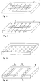
- the foam element shown in Fig. 1 comprises a foam body 1, in the a lattice structure consisting of longitudinal and transverse strands 3, 4 is used.
- the Lattice structure runs in a plane parallel to the surface of the foam body almost over the entire length or width of the foam body.
- the longitudinal and Cross strands 3, 4 are arranged at constant distances from one another.
- the lattice structure shown in Fig. 2 consists of an essentially non-elastic Material and is by anchoring plate 6 on the long sides of the body 1 in Transverse direction held under tension.
- the longitudinal strands 3 of the lattice structure are not biased against it.
- At least at one end of the cross strands 4 elastic tension cords 5 are attached with which the grid insert is biased.
- Such a foam element is produced by foaming one corresponding layer material, in the present case the lattice structure, whereby a one-piece foam body 1 is formed.
- the longitudinal and transverse strands 3, 4 are in evenly spaced.
- the longitudinal and transverse strands 3, 4 are in evenly spaced.
- Fig. 3 shows a foam body 1 with an inserted bubble wrap 7.
- the bubble wrap 7 is placed on a holder, preferably in the form of a needle bed, and also made of foam material foamed.
- the air bubbles in the film 7 are so strong that they are Withstand pressure when foaming.
- the foam element shown in FIG. 4 comprises a foam body 1 with in Bands 8 inserted in the transverse direction, e.g. made of felt, fleece, cloth or plastic.
- the individual bands are 8 in arranged at different distances.
- the distance between the individual bands 8 less than e.g. in the head-shoulder area B, where the body is deeper must sink in to adopt an ergonomic posture.
- the bands can optionally be prestressed.
- the foam element shown in Fig. 5 has a plurality of air passage channels 11, which the top and bottom are aligned.
- the channels 11 extend up to a reinforcement layer 10, which preferably consists of a air-permeable material or in the places of the air passage channels a Has 11 recesses. This creates through the foam element through ventilation channels that remove moisture from the inside allow the mattress to the outside.
- FIG. 6 shows a foam element 1 with a plurality of cavities 12 and one Reinforcement layer 2, which at least in certain zones of the mattress above the Hollow body 12 is arranged to reinforce the mattress in this area.
- the mattress shown in Fig. 7 has several layers of layer material 2.2 ', in this Example are arranged asymmetrically with respect to a central plane. This creates one Reversible mattress with lying surfaces of different hardness. Between Reinforcement layers can in turn be arranged in cavities 12.
- the invention contains Foam element a frame 13 shown in Fig. 8, in which a grid as Layer material 2 is clamped.
- the frame 13 is approximately the size of the mattress and is foamed together with the layer material 2 by the foam of the mattress.
- the frame can also be placed outside the mattress.
Landscapes
- Mattresses And Other Support Structures For Chairs And Beds (AREA)
- Laminated Bodies (AREA)
Abstract
Description
Claims (18)
- Schaumstoffelement, insbesondere für eine Matratze aus PU-Schaum oder Latex, dadurch gekennzeichnet, dass ein Schichtmaterial (2) in das Schaumstoffelement (1) eingelegt ist und von diesem umschäumt ist.
- Schaumstoffelement nach Anspruch 1, dadurch gekennzeichnet, dass das Schichtmaterial (2) folienartig ist oder aus Gewebe besteht.
- Schaumstoffelement nach Anspruch 1 oder 2, dadurch gekennzeichnet, dass das Schichtmaterial (2) eine Gitterstruktur mit Längst und Quersträngen hat.
- Schaumstoffelement nach Anspruch 3, dadurch gekennzeichnet, dass wenigstens ein Teil der Längs- oder Querstränge (3,4) elastisch ist.
- Schaumstoffelement nach Anspruch 1, dadurch gekennzeichnet, dass mehrere Bänder, insbesondere in Querrichtung einer Matratze, angeordnet sind.
- Schaumstoffelement nach einem der vorhergehenden Ansprüche, dadurch gekennzeichnet, dass das Schichtmaterial (2) unter Vorspannung in das Schaumstoffelement (1) eingebracht wird.
- Schaumstoffelement nach Anspruch 3 oder 4, dadurch gekennzeichnet, dass der Gitterabstand der einzelnen Stränge je nach Körperzone unterschiedlich ist.
- Schaumstoffelement nach einem der vorhergehenden Ansprüche, dadurch gekennzeichnet, dass der Abstand des Schichtmaterials (2) von der Oberseite des Schaumstoffelements (1) je nach Körperzone unterschiedlich ist.
- Schaumstoffelement nach einem der vorhergehenden Ansprüche, dadurch gekennzeichnet, dass das Schichtmaterial (2) im Schaumstoffelement (1) oder an den Seiten des Schaumstoffelements (1) verankert ist.
- Schaumstoffelement nach einem der vorhergehenden Ansprüche, dadurch gekennzeichnet, dass das Schichtmaterial (2) beim Schäumen durch Spannschnüre gehalten wird, die sich nach dem Kappen ins Innere des Schaumstoffelements (1) zurückziehen.
- Schaumstoffelement nach einem der vorhergehenden Ansprüche, dadurch gekennzeichnet, dass das Schichtmaterial auf Stiften gehalten wird, die nach dem Aushärten des Materials herausgenommen werden.
- Schaumstoffelement nach einem der vorhergehenden Ansprüche, dadurch gekennzeichnet, dass auf beiden Seiten des Schichtmaterials Lüftungskanäle gebildet sind.
- Schaumstoffelement nach einem der vorhergehenden Ansprüche, dadurch gekennzeichnet, dass das Schaumstoffelement (1) einstöckig ist.
- Schaumstoffelement nach einem der vorhergehenden Ansprüche, dadurch gekennzeichnet, dass das Schichtmaterial (2) in mehreren Lagen, insbesondere asymmetrisch bezüglich einer Mittelebene, übereinander angeordnet ist.
- Schaumstoffelement nach einem der vorhergehenden Ansprüche, dadurch gekennzeichnet, dass das Schaumstoffelement (1) Hohlräume (1.2) umfasst.
- Schaumstoffelement nach einem der vorhergehenden Ansprüche, dadurch gekennzeichnet, dass das Schichtmaterial (2) zumindest in bestimmten Bereichen oberhalb der Hohlkörper angeordnet ist.
- Schaumstoffelement nach einem der vorhergehenden Ansprüche, dadurch gekennzeichnet, dass das Schichtmaterial (2) in einem Rahmen (13) eingespannt ist.
- Schaumstoffelement nach Anspruch 17, dadurch gekennzeichnet, dass der Rahmen (13) im Schaumstoffelement (1) eingeschäumt ist.
Applications Claiming Priority (2)
| Application Number | Priority Date | Filing Date | Title |
|---|---|---|---|
| DE20019160U | 2000-11-10 | ||
| DE20019160U DE20019160U1 (de) | 2000-11-10 | 2000-11-10 | Schaumstoffelement mit Verstärkungsschicht |
Publications (3)
| Publication Number | Publication Date |
|---|---|
| EP1205132A2 true EP1205132A2 (de) | 2002-05-15 |
| EP1205132A3 EP1205132A3 (de) | 2004-01-14 |
| EP1205132B1 EP1205132B1 (de) | 2008-05-07 |
Family
ID=7948689
Family Applications (1)
| Application Number | Title | Priority Date | Filing Date |
|---|---|---|---|
| EP01126838A Expired - Lifetime EP1205132B1 (de) | 2000-11-10 | 2001-11-10 | Schaumstoffelement mit Verstärkungsschicht |
Country Status (3)
| Country | Link |
|---|---|
| EP (1) | EP1205132B1 (de) |
| AT (1) | ATE394049T1 (de) |
| DE (2) | DE20019160U1 (de) |
Cited By (4)
| Publication number | Priority date | Publication date | Assignee | Title |
|---|---|---|---|---|
| EP1854610A3 (de) * | 2006-05-11 | 2009-05-27 | Sapsa Bedding S.R.L. | Kontinuierliches Verfahren und Vorrichtung zum Herstellen von Gegenständen aus Latexschaum |
| ITPI20090041A1 (it) * | 2009-04-09 | 2010-10-10 | Gommec S R L | Metodo di fabbricazione di una lastra in microporosa e lastra cosi ottenuta |
| CN107397377A (zh) * | 2017-08-09 | 2017-11-28 | 格联特(厦门)休闲用品有限公司 | 一种海绵床垫及其加工工艺 |
| US20190357695A1 (en) * | 2016-09-23 | 2019-11-28 | Covestro Deutschland Ag | Composite object comprising a body and a foam, and method for production thereof |
Family Cites Families (4)
| Publication number | Priority date | Publication date | Assignee | Title |
|---|---|---|---|---|
| CH407451A (de) * | 1963-12-10 | 1966-02-15 | Schroeder Georges | Matratze oder Polster |
| US4080675A (en) * | 1976-03-08 | 1978-03-28 | Allied Upholstery Mfg., Inc. | Cushion construction |
| CH619852A5 (de) * | 1977-09-27 | 1980-10-31 | Marpal Ag | |
| AT370603B (de) * | 1981-06-26 | 1983-04-25 | Semperit Ag | Matratzenkern aus kunststoff- oder latexschaum |
-
2000
- 2000-11-10 DE DE20019160U patent/DE20019160U1/de not_active Expired - Lifetime
-
2001
- 2001-11-10 AT AT01126838T patent/ATE394049T1/de not_active IP Right Cessation
- 2001-11-10 DE DE50113934T patent/DE50113934D1/de not_active Expired - Lifetime
- 2001-11-10 EP EP01126838A patent/EP1205132B1/de not_active Expired - Lifetime
Cited By (7)
| Publication number | Priority date | Publication date | Assignee | Title |
|---|---|---|---|---|
| EP1854610A3 (de) * | 2006-05-11 | 2009-05-27 | Sapsa Bedding S.R.L. | Kontinuierliches Verfahren und Vorrichtung zum Herstellen von Gegenständen aus Latexschaum |
| US7604761B2 (en) | 2006-05-11 | 2009-10-20 | Sapsa Bedding Srl | Process and plant for continuous manufacture of latex foam articles |
| ITPI20090041A1 (it) * | 2009-04-09 | 2010-10-10 | Gommec S R L | Metodo di fabbricazione di una lastra in microporosa e lastra cosi ottenuta |
| WO2010116252A2 (en) | 2009-04-09 | 2010-10-14 | Gommec S.R.L. | Method for making a surface reinforced foam rubber board and foam rubber board obtained with this method |
| WO2010116252A3 (en) * | 2009-04-09 | 2013-05-23 | Gommec S.R.L. | Method for making a surface reinforced foam rubber board and foam rubber board obtained with this method |
| US20190357695A1 (en) * | 2016-09-23 | 2019-11-28 | Covestro Deutschland Ag | Composite object comprising a body and a foam, and method for production thereof |
| CN107397377A (zh) * | 2017-08-09 | 2017-11-28 | 格联特(厦门)休闲用品有限公司 | 一种海绵床垫及其加工工艺 |
Also Published As
| Publication number | Publication date |
|---|---|
| ATE394049T1 (de) | 2008-05-15 |
| EP1205132A3 (de) | 2004-01-14 |
| EP1205132B1 (de) | 2008-05-07 |
| DE50113934D1 (de) | 2008-06-19 |
| DE20019160U1 (de) | 2001-01-11 |
Similar Documents
| Publication | Publication Date | Title |
|---|---|---|
| DE2510182A1 (de) | Sitz- bzw. rueckenpolster, insbesondere fuer fahrzeugsitze u.dgl. | |
| DE1271333B (de) | In eine Sitzschale verformbare, nach allen Richtungen durchbiegbare Platte | |
| EP3393303B1 (de) | Schaumstoffkern für ein polster eines sitzteils oder eines liegeteils oder einer rückenlehne eines polstermöbels oder eines fahrzeugsitzes | |
| DE29805926U1 (de) | Sitzpolster für Fahrzeugsitze | |
| DE7227754U (de) | Sitz,insbesondere autositz | |
| DE2841870C2 (de) | ||
| AT504204B1 (de) | Aus schaumstoff bestehende polsterung | |
| EP1842458A2 (de) | Polsternder Schaumstoffkörper, insbesondere für Kraftfahrzeugsitze | |
| WO2008043413A1 (de) | Klimatisierter fahrzeugsitz | |
| EP1205132B1 (de) | Schaumstoffelement mit Verstärkungsschicht | |
| WO2017144662A1 (de) | Sitzkissen für einen fahrzeugsitz, insbesondere einen flugzeugsitz | |
| DE102016003417A1 (de) | Unterfederung für eine Polsterung und Möbel mit einer Unterfederung | |
| DE102015015872A1 (de) | Liegemodul und Verfahren zur Herstellung eines Liegemoduls | |
| DE7507389U (de) | Sitz- bzw. rueckenpolster, insbesondere fuer fahrzeugsitze u.dgl. | |
| DE69611490T2 (de) | Matratze mit Einstellung der Festigkeit | |
| DE10030623C1 (de) | Unterfederung für Polsterauflagen, wie Matratzen | |
| DE19610360C1 (de) | Matratze mit Versteifungslamellen im Schaumstoffkörper | |
| EP0670128B1 (de) | Untermatratze | |
| EP2528475B1 (de) | Sitzmöbel | |
| DE202007017626U1 (de) | Matratze | |
| CH452156A (de) | Mehrschichtenbauplatte und Verfahren zu deren Herstellung | |
| EP1629815A1 (de) | Matratze | |
| DE7930103U1 (de) | Latte fuer bett- oder lattenrost | |
| DE4137677C1 (en) | Bottom frame for bed - has longitudinal stringers covered by flexible cross-slats | |
| DE102025003200A1 (de) | Matratze mit integrierten Versteifungsstreben |
Legal Events
| Date | Code | Title | Description |
|---|---|---|---|
| PUAI | Public reference made under article 153(3) epc to a published international application that has entered the european phase |
Free format text: ORIGINAL CODE: 0009012 |
|
| AK | Designated contracting states |
Kind code of ref document: A2 Designated state(s): AT BE CH CY DE DK ES FI FR GB GR IE IT LI LU MC NL PT SE TR |
|
| AX | Request for extension of the european patent |
Free format text: AL;LT;LV;MK;RO;SI |
|
| PUAL | Search report despatched |
Free format text: ORIGINAL CODE: 0009013 |
|
| AK | Designated contracting states |
Kind code of ref document: A3 Designated state(s): AT BE CH CY DE DK ES FI FR GB GR IE IT LI LU MC NL PT SE TR |
|
| AX | Request for extension of the european patent |
Extension state: AL LT LV MK RO SI |
|
| RIC1 | Information provided on ipc code assigned before grant |
Ipc: 7A 47C 27/16 B Ipc: 7A 47C 27/14 A |
|
| 17P | Request for examination filed |
Effective date: 20040608 |
|
| AKX | Designation fees paid |
Designated state(s): AT BE CH CY DE DK ES FI FR GB GR IE IT LI LU MC NL PT SE TR |
|
| 17Q | First examination report despatched |
Effective date: 20061030 |
|
| GRAP | Despatch of communication of intention to grant a patent |
Free format text: ORIGINAL CODE: EPIDOSNIGR1 |
|
| GRAS | Grant fee paid |
Free format text: ORIGINAL CODE: EPIDOSNIGR3 |
|
| GRAA | (expected) grant |
Free format text: ORIGINAL CODE: 0009210 |
|
| AK | Designated contracting states |
Kind code of ref document: B1 Designated state(s): AT BE CH CY DE DK ES FI FR GB GR IE IT LI LU MC NL PT SE TR |
|
| REG | Reference to a national code |
Ref country code: GB Ref legal event code: FG4D Free format text: NOT ENGLISH |
|
| REG | Reference to a national code |
Ref country code: CH Ref legal event code: EP |
|
| REG | Reference to a national code |
Ref country code: IE Ref legal event code: FG4D Free format text: LANGUAGE OF EP DOCUMENT: GERMAN |
|
| REF | Corresponds to: |
Ref document number: 50113934 Country of ref document: DE Date of ref document: 20080619 Kind code of ref document: P |
|
| PG25 | Lapsed in a contracting state [announced via postgrant information from national office to epo] |
Ref country code: NL Free format text: LAPSE BECAUSE OF FAILURE TO SUBMIT A TRANSLATION OF THE DESCRIPTION OR TO PAY THE FEE WITHIN THE PRESCRIBED TIME-LIMIT Effective date: 20080507 Ref country code: ES Free format text: LAPSE BECAUSE OF FAILURE TO SUBMIT A TRANSLATION OF THE DESCRIPTION OR TO PAY THE FEE WITHIN THE PRESCRIBED TIME-LIMIT Effective date: 20080818 Ref country code: FI Free format text: LAPSE BECAUSE OF FAILURE TO SUBMIT A TRANSLATION OF THE DESCRIPTION OR TO PAY THE FEE WITHIN THE PRESCRIBED TIME-LIMIT Effective date: 20080507 |
|
| NLV1 | Nl: lapsed or annulled due to failure to fulfill the requirements of art. 29p and 29m of the patents act | ||
| REG | Reference to a national code |
Ref country code: IE Ref legal event code: FD4D |
|
| PG25 | Lapsed in a contracting state [announced via postgrant information from national office to epo] |
Ref country code: IE Free format text: LAPSE BECAUSE OF FAILURE TO SUBMIT A TRANSLATION OF THE DESCRIPTION OR TO PAY THE FEE WITHIN THE PRESCRIBED TIME-LIMIT Effective date: 20080507 Ref country code: DK Free format text: LAPSE BECAUSE OF FAILURE TO SUBMIT A TRANSLATION OF THE DESCRIPTION OR TO PAY THE FEE WITHIN THE PRESCRIBED TIME-LIMIT Effective date: 20080507 Ref country code: SE Free format text: LAPSE BECAUSE OF FAILURE TO SUBMIT A TRANSLATION OF THE DESCRIPTION OR TO PAY THE FEE WITHIN THE PRESCRIBED TIME-LIMIT Effective date: 20080807 Ref country code: PT Free format text: LAPSE BECAUSE OF FAILURE TO SUBMIT A TRANSLATION OF THE DESCRIPTION OR TO PAY THE FEE WITHIN THE PRESCRIBED TIME-LIMIT Effective date: 20081007 |
|
| PLBE | No opposition filed within time limit |
Free format text: ORIGINAL CODE: 0009261 |
|
| STAA | Information on the status of an ep patent application or granted ep patent |
Free format text: STATUS: NO OPPOSITION FILED WITHIN TIME LIMIT |
|
| 26N | No opposition filed |
Effective date: 20090210 |
|
| BERE | Be: lapsed |
Owner name: MANKAU, DIETER, PROF. Effective date: 20081130 |
|
| PG25 | Lapsed in a contracting state [announced via postgrant information from national office to epo] |
Ref country code: MC Free format text: LAPSE BECAUSE OF NON-PAYMENT OF DUE FEES Effective date: 20081130 |
|
| REG | Reference to a national code |
Ref country code: CH Ref legal event code: PL |
|
| GBPC | Gb: european patent ceased through non-payment of renewal fee |
Effective date: 20081110 |
|
| PG25 | Lapsed in a contracting state [announced via postgrant information from national office to epo] |
Ref country code: IT Free format text: LAPSE BECAUSE OF FAILURE TO SUBMIT A TRANSLATION OF THE DESCRIPTION OR TO PAY THE FEE WITHIN THE PRESCRIBED TIME-LIMIT Effective date: 20080507 |
|
| PG25 | Lapsed in a contracting state [announced via postgrant information from national office to epo] |
Ref country code: BE Free format text: LAPSE BECAUSE OF NON-PAYMENT OF DUE FEES Effective date: 20081130 |
|
| PG25 | Lapsed in a contracting state [announced via postgrant information from national office to epo] |
Ref country code: LI Free format text: LAPSE BECAUSE OF NON-PAYMENT OF DUE FEES Effective date: 20081130 Ref country code: CH Free format text: LAPSE BECAUSE OF NON-PAYMENT OF DUE FEES Effective date: 20081130 |
|
| PG25 | Lapsed in a contracting state [announced via postgrant information from national office to epo] |
Ref country code: GB Free format text: LAPSE BECAUSE OF NON-PAYMENT OF DUE FEES Effective date: 20081110 |
|
| PG25 | Lapsed in a contracting state [announced via postgrant information from national office to epo] |
Ref country code: AT Free format text: LAPSE BECAUSE OF NON-PAYMENT OF DUE FEES Effective date: 20081110 |
|
| PG25 | Lapsed in a contracting state [announced via postgrant information from national office to epo] |
Ref country code: LU Free format text: LAPSE BECAUSE OF NON-PAYMENT OF DUE FEES Effective date: 20081110 Ref country code: CY Free format text: LAPSE BECAUSE OF FAILURE TO SUBMIT A TRANSLATION OF THE DESCRIPTION OR TO PAY THE FEE WITHIN THE PRESCRIBED TIME-LIMIT Effective date: 20080507 |
|
| PG25 | Lapsed in a contracting state [announced via postgrant information from national office to epo] |
Ref country code: TR Free format text: LAPSE BECAUSE OF FAILURE TO SUBMIT A TRANSLATION OF THE DESCRIPTION OR TO PAY THE FEE WITHIN THE PRESCRIBED TIME-LIMIT Effective date: 20080507 |
|
| PG25 | Lapsed in a contracting state [announced via postgrant information from national office to epo] |
Ref country code: GR Free format text: LAPSE BECAUSE OF FAILURE TO SUBMIT A TRANSLATION OF THE DESCRIPTION OR TO PAY THE FEE WITHIN THE PRESCRIBED TIME-LIMIT Effective date: 20080808 |
|
| PGFP | Annual fee paid to national office [announced via postgrant information from national office to epo] |
Ref country code: FR Payment date: 20111213 Year of fee payment: 11 |
|
| PGFP | Annual fee paid to national office [announced via postgrant information from national office to epo] |
Ref country code: DE Payment date: 20120628 Year of fee payment: 12 |
|
| REG | Reference to a national code |
Ref country code: FR Ref legal event code: ST Effective date: 20130731 |
|
| PG25 | Lapsed in a contracting state [announced via postgrant information from national office to epo] |
Ref country code: FR Free format text: LAPSE BECAUSE OF NON-PAYMENT OF DUE FEES Effective date: 20121130 |
|
| PG25 | Lapsed in a contracting state [announced via postgrant information from national office to epo] |
Ref country code: DE Free format text: LAPSE BECAUSE OF NON-PAYMENT OF DUE FEES Effective date: 20140603 |
|
| REG | Reference to a national code |
Ref country code: DE Ref legal event code: R119 Ref document number: 50113934 Country of ref document: DE Effective date: 20140603 |