EP1205151B1 - Appareil-cible pour ostéotomie transfémorale - Google Patents
Appareil-cible pour ostéotomie transfémorale Download PDFInfo
- Publication number
- EP1205151B1 EP1205151B1 EP01309438A EP01309438A EP1205151B1 EP 1205151 B1 EP1205151 B1 EP 1205151B1 EP 01309438 A EP01309438 A EP 01309438A EP 01309438 A EP01309438 A EP 01309438A EP 1205151 B1 EP1205151 B1 EP 1205151B1
- Authority
- EP
- European Patent Office
- Prior art keywords
- femur
- targeting apparatus
- support element
- proximal
- securing
- Prior art date
- Legal status (The legal status is an assumption and is not a legal conclusion. Google has not performed a legal analysis and makes no representation as to the accuracy of the status listed.)
- Expired - Lifetime
Links
- 230000008685 targeting Effects 0.000 title claims description 22
- 210000000689 upper leg Anatomy 0.000 claims description 59
- 210000000988 bone and bone Anatomy 0.000 claims description 19
- 210000004872 soft tissue Anatomy 0.000 claims description 8
- 238000001356 surgical procedure Methods 0.000 claims description 8
- 210000002414 leg Anatomy 0.000 claims description 5
- 238000005553 drilling Methods 0.000 claims description 3
- 238000010276 construction Methods 0.000 description 11
- 230000000007 visual effect Effects 0.000 description 5
- 125000006850 spacer group Chemical group 0.000 description 3
- 238000000034 method Methods 0.000 description 2
- 230000000717 retained effect Effects 0.000 description 2
- 238000004873 anchoring Methods 0.000 description 1
- 238000009963 fulling Methods 0.000 description 1
- 239000007943 implant Substances 0.000 description 1
- 210000003127 knee Anatomy 0.000 description 1
- 239000000463 material Substances 0.000 description 1
- 238000005259 measurement Methods 0.000 description 1
- 210000003205 muscle Anatomy 0.000 description 1
- 238000012829 orthopaedic surgery Methods 0.000 description 1
- 230000002980 postoperative effect Effects 0.000 description 1
- 230000003019 stabilising effect Effects 0.000 description 1
Images



Classifications
-
- A—HUMAN NECESSITIES
- A61—MEDICAL OR VETERINARY SCIENCE; HYGIENE
- A61B—DIAGNOSIS; SURGERY; IDENTIFICATION
- A61B17/00—Surgical instruments, devices or methods
- A61B17/16—Instruments for performing osteoclasis; Drills or chisels for bones; Trepans
- A61B17/17—Guides or aligning means for drills, mills, pins or wires
- A61B17/1739—Guides or aligning means for drills, mills, pins or wires specially adapted for particular parts of the body
- A61B17/1742—Guides or aligning means for drills, mills, pins or wires specially adapted for particular parts of the body for the hip
- A61B17/175—Guides or aligning means for drills, mills, pins or wires specially adapted for particular parts of the body for the hip for preparing the femur for hip prosthesis insertion
-
- A—HUMAN NECESSITIES
- A61—MEDICAL OR VETERINARY SCIENCE; HYGIENE
- A61B—DIAGNOSIS; SURGERY; IDENTIFICATION
- A61B17/00—Surgical instruments, devices or methods
- A61B17/16—Instruments for performing osteoclasis; Drills or chisels for bones; Trepans
- A61B17/17—Guides or aligning means for drills, mills, pins or wires
- A61B17/1739—Guides or aligning means for drills, mills, pins or wires specially adapted for particular parts of the body
- A61B17/1742—Guides or aligning means for drills, mills, pins or wires specially adapted for particular parts of the body for the hip
- A61B17/1753—Guides or aligning means for drills, mills, pins or wires specially adapted for particular parts of the body for the hip for fixing pins through femoral hip prostheses
Definitions
- This invention relates to a targeting apparatus for use in performing transfemoral osteotomy.
- the femur is exposed along a proximal/distal line, the soft tissue (skin, muscle) being folded back on each side to expose the bone.
- the proximal end of the femur is now opened as a "window" and a femoral prosthesis is inserted into the bone canal.
- the technique requires careful pre-operative planning, usually from X-rays and it is possible to calculate in advance how far to cut the "window” so that the distal edge of the "window” end can become a datum base.
- US 4 667 664 shows a blind hole targeting device for orthopaedic surgery which is for use when drilling holes in the bone of a femur when installing an intramedullary nail in the medullary canal.
- the device provides a support element provided with a drill guide, means for securing the support element to the intramedullary nail and a stabilising arm for connection to the femur for providing extra stability to the support element.
- a drill guide is also provided at the proximal end of the support element for drilling holes through the bone.
- This type of targeting apparatus would be totally unsuitable for use when performing transfemoral osteotomy because there is no provision or, indeed, requirement to alter the relative angular position of the drill guides about the longitudinal proximal/distal axis of the intramedullary canal and there is also no provision for adjusting the relative angle of the support element in relation to the insert.
- the present invention is intended to overcome some of the difficulties preferred to above and provide apparatus which provides a more accurate surgical technique.
- the apparatus can be used to accurately locate the angular position of the drill guide and the prosthesis (anteversion setting) which can be used to drill the holes to take the retaining bolt or bolts in the bone.
- targeting apparatus for use in performing transfemoral osteotomy on a femur (6) which has been resected longitudinally along a proximal/distal line (L) and opened as a "window” and comprising a support element (1) provided with a drill guide (2), means (3) for securing the support element (1) to a prosthesis (4) to be implanted, and characterised by means (15)(31) for clamping said support element (1) to the unopened part of a resected femur (6) and means (25)(15)(16) for adjusting the angular position of the drill guide (2) in relation to the resectioned femur (6) by revolving it about a proximal/distal axis.
- the support element includes means for connection to the proximal end of the femoral prosthesis.
- Means can be provided to indicate the angular position of the drill guide relative to the resectioned femur.
- the apparatus can also include means for adjusting the support element to accommodate alternative leg lengths. In order to do this means can be included to vary the proximal-distal position of the support element in relation to the prosthesis securing means.
- the drill guide can be located at a predetermined proximal/distal position from the means for connection to the proximal end of the femoral prosthesis.
- Means can be included for locating the drill guide in alternative proximal/distal positions on the support element thus the apparatus can be adapted for prostheses with holes in different positions and two or more drill guides can be provided.
- the means for securing the support element to the resectioned femur is preferably in the form of an adjustable open jawed clamp adapted to partially surround the femur with which it is to be used.
- Guide means can be included for locating the support element on the resectioned proximal end of the femur and these guide means can be carried on the femur securing means.
- the support element can be in the form of an L-shaped frame, one arm of which carries the drill guide and the femur securing means and the other arm carrying the means for connection to the femoral prosthesis which is to be implanted.
- the femur securing means can be connected to the L-shaped frame by a bracket which can be adjusted in proximal-distal directions on the frame and in relation to which the femur securing means can be angularly adjusted about a proximal-distal axis.
- bracket is readily removable from the L-shaped frame.
- the femur securing means can include means for adjusting and clamping the securing means according to the femur diameter.
- the means for securing the support element to the resectioned femur includes a universal joint.
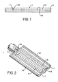
- Figures 1 and 2 show, in simplified form, transfemoral osteotomy surgery is performed.
- the soft tissue indicated by reference letter T in Figure 2 is exposed along a proximal/distal line indicated by chain line L in Figure 2.
- the soft tissue T is folded back on each side to expose the femur 6 and the bone is resected with three cuts along the same line L two side cuts M and with a transverse cut C.
- the proximal end of the femur is now opened, as shown in Figure 2, as a "window". From Figure 2 it will be seen that an upper quarter 48 is now laid on each side of the remaining part of the bone to expose the bone canal into which the prosthesis is to be inserted.
- Adjustment means 7 are included for adjusting the angular position of the drill guides 2 in relation to the resectioned femur 6 about a proximal-distal axis.
- the support element 1 is in the form of an L-shaped frame having a first arm 10 and a second arm 11.
- the first arm 10 carries the drill guides 2 and the femur securing means 5 and the second arm 11 carries the means 3 for connecting the support 1 to proximal end of the femoral prosthesis 4.
- the femur securing means 5 (to be described below) is connected to the first arm 10 by an adjustable bracket 12 which can be adjusted in proximal-distal directions only in a slot 13 in the arm 10 and locked in position by a retaining nut 14, and the femur securing means 5 can be angularly adjusted in relation to the bracket 12 in a slot 15 provided on the bracket and locked in position by a nut 16.
- the nut 16 is carried on a screw threaded boss indicated by reference numeral 17 which is carried on the femur securing means 5.
- the means 3 for connecting the support element 1 to the femoral prosthesis which is to be implanted is shown in more detail in Figure 4 and comprises a sleeve 20 secured to the second arm 11 and in which is located a securing stud 21.
- the proximal end 22 of the prosthesis 4 is provided with a screw threaded bore 23 in which a screw threaded portion 24 of the stud 21 can be located.
- the other end of the stud is held by a nut 25.
- the distal end of the sleeve 20 is provided with a pair of opposed projecting keys 26 which engage in keyways 27 in the form of slots provided in an enlarged end portion of the bore 23.
- the prosthesis 4 can be held in position on the arm 11 and is restrained against relative rotation by the keys 26 and keyways 27.
- the means 5 for securing the support element to a resectioned femur 6 is most clearly shown in Figures 5 and 6 and comprises an open-jawed clamp device.
- This device has a main body portion 30 on which is located a movable clamping jaw 31.
- the upper part of the clamping jaw 31 has a screw threaded bore 32 which houses a threaded member 33 one end of which carries an operating handle 34 and the other end of which is rotatably housed in the body 30.
- rotation of the handle 34 raises and lowers the clamp 31 which is also located by a retaining screw 35 which passes through a slot 136.
- the lower end of the open jawed clamp is formed as a pair of curved tines 36 which are adapted to extend around the resectioned femur to which the device is to be clamped.
- the boss 17 is located in a slot 40 in the body 30 and held by a nut 37 but is free to move so that the position of the clamp adjusts itself in relation to the adjustment bracket 12 to alter the radial distance from the femur 6.
- the drill guides 2 are carried on the arm 10 by a clamping plate 40 which is held in place by a screw threaded shaft 41 retained by a nut 42.
- the shaft 41 passes through one of a series of four openings 43 in the arm 1.
- the drill guides 2 are set for a position with respect to the given prosthesis so that they are fixed and aligned with the holes 44 in the prosthesis 4.
- a typical drill bit 45 is shown in place in one of the drill guides 2 and its lower operative end 46 indicates how it has been drilled through the femur 6 passing through the existing holes 44 in the stem 47 and through the other side of the femur 6.
- the second arm 11 can be arranged to be detachable from the support element 1 and is secured to the arm 10 by a plug and socket connection indicated by reference numeral 90.
- a triangular socket 91 is provided in the arm 10 into which a triangular shaped plug on the arm 11 is inserted.
- the plug 92 is retained in position by a locking screw 93 in the end of the arm.
- the surgeon To carry out the surgery relating to a transfemoral osteotomy the surgeon first ensures that appropriate X-rays have been taken so that he can consider the amount of bone which needs to be removed from the femur. Once having decided this the measurements are carefully taken for further use with the apparatus according to the invention.
- the "window” is now opened to reveal the femur and the bone is cut appropriately to provide a proximal end C , indicated by reference numeral 49 in Figure 3.
- the clamp 5 is now located in position on the end of the femur by tucking it around the femoral end and ensuring that the guide disc 38 is close up against the severed end 49. The positioning is achieved with a rotative movement. Once in place the handle 34 is operated to close the clamp and retain it in place.
- the stem 47 of the prosthesis 4 is now inserted in the femoral canal and the frame in the form of the arms 10 and 11 is connected to it by means of the securing means 3.
- the nut 14 is released to allow the bracket 12 to move in the slot 13 and so that it can be secured to the femur securing means 5 by the boss 17 and nut 16 through the slot 15.
- the release of the nut 16 allows the slot 15 to be placed on the boss 17 at the appropriate radial distance from the femur prior to subsequent tightening.
- the ante/retroversion adjustment is now carried out by revolving the frame about the axis of the prosthesis 4 and the particular angle adjustment is set by tightening the nut 16. During this angular movement the prosthesis 4 which is securely attached to the support frame revolves with it as do the drill guides 2.
- the proximal-distal positioning of the drill guides is set according to the pre-operative planning and they are now positioned by releasing the nut 42 so that they can be located in contact with the cortex of the femur and the nut suitably tightened.
- the drill guides can now be used to produce the necessary holes through the bone to accept the required bolts or pins.
- the apparatus can be simply removed by releasing the stud 21 in the prosthesis 4, releasing the nut 16 and removing the frame.
- the clamp 6 can be removed separately.
- FIG. 7 shows an alternative construction in which the same reference numerals are used to indicate similar parts.
- the adjustable bracket 12 can be readily disconnected from the first arm 10 of the L-shaped frame.
- the nut 14 is shown as a hand nut and is carried on a boss 50 which has a bore 51 adapted to receive a spigot 52 provided on the end of the bracket 12.
- the boss 50 also carries a screw threaded locking nut 53 which can be advanced through a screw threaded bore (not shown) so that it engages against the spigot 52 where it is located in the bore 51 to clamp it in position.
- This construction enables disconnection of the assembly without having to unscrew the locking nut 14 thus enabling the leg length to be set without readjustment.
- FIG 8, 9 and 10 show an alternative construction for the open jawed clamp device and the same reference numerals are used to indicate similar parts to those shown in Figures 5 and 6.
- the boss 17 is replaced by a bolt 60 which extends through the slot 40 and carries a spacer 61.
- One end 62 of the spacer is dished to accommodate a part-spherically shaped washer 63.
- a second part spherically-shaped washer 64 is also located on the screw 60 and one side of this is housed in a dished portion 65 of a nut 66.
- the nut 66 has a circumferential groove 67 to accommodate resilient ring (not shown) which can act to retain a socket wrench during assembly.
- Each of the washers 64 and 63 also has a flat side which are located against the sides of the slot 15 on the bracket 12 when the whole construction is assembled together with the screw 60 passing through the slot 15.
- the bracket 12 can align itself in three different directions by movement of the part spherical washers in the spacers 61 and 65. This enables three relative rotations, one of which is the anteversion setting and the other two rotations enable centring of the stem in the femur if the clamp is ill positioned on it.
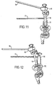
- Figure 11 shows how visual indicator guides can be provided.
- a visual indicator guide arm 70 is attached to the L-shaped frame 10 in the form of a rod which extends at 15° to the axis of the first arm 10.
- a second indicator guide 71 which is also in the form of a rod is attached at an angle normal to the longitudinal axis of the clamp main body portion 30.
- the apparatus is placed in position with the clamp positioned perpendicular to the 90° knee flexion plane. This is the first position of the anteversion at 0° and this is shown in Figure 11.
- Figure 12 the L-shaped frame 10 has been rotated until the visual indicator guides 70, 71 are parallel.
- the frame 10 has been rotated through 15° in relation to the clamp 30.
- the neck axis is parallel to the axis of the frame 10 and the rotation of the frame has thus created an angle between the clamp and the frame which is the anteversion angle.
- the exact angle of anteversion can be read from a scale indicated by reference numeral 72 provided on the bracket 12.
- the standard value of anteversion is 15° and this can be used as a datum when setting up the apparatus.
- FIG 13 shows how a proximal drill guide 75 can be provided to guide drills through the folded back "flap” and to enable the drills to line up with pre-arranged holes 76 provided on the prosthesis 4.
- This device is in the form of an open jawed clamping block 77 which is provided with a tightening screw 78 which passes through a threaded bore (not shown) in the block to extend into the gap 79 provided between a lower clamping jaw 80 and an upper clamping jaw 81.
- the clamping block 77 carries an arm 82 which supports a pair of drill guides 83.
- the prosthesis is provided with a series of openings 76.
- the clamping block With the prosthesis in position in the support element 1 and held by the second arm 11 the clamping block is placed in position and the drill guides are aligned by the use of guide rods or drills 84. With the drill guides now aligned with the openings 76 the clamping screw 78 is tightened to lock the clamping block in position.
- the rods or drills 84 can now be removed, the "window" is closed and the drill guides employed to guide the drill or drills to make openings in the flap of bone and soft tissue 48.
- the openings can then be located by passing wire hoops through the openings and suitably locating them thus ensuring that the flap of material is held in place.
Landscapes
- Health & Medical Sciences (AREA)
- Surgery (AREA)
- Life Sciences & Earth Sciences (AREA)
- Biomedical Technology (AREA)
- Medical Informatics (AREA)
- Orthopedic Medicine & Surgery (AREA)
- Oral & Maxillofacial Surgery (AREA)
- Engineering & Computer Science (AREA)
- Dentistry (AREA)
- Heart & Thoracic Surgery (AREA)
- Nuclear Medicine, Radiotherapy & Molecular Imaging (AREA)
- Molecular Biology (AREA)
- Animal Behavior & Ethology (AREA)
- General Health & Medical Sciences (AREA)
- Public Health (AREA)
- Veterinary Medicine (AREA)
- Surgical Instruments (AREA)
- Prostheses (AREA)
Claims (17)
- Dispositif de visée destiné à être utilisé pour effectuer une chirurgie d'ostéotomie transfémorale sur un fémur (6) qui a subi une résection longitudinale le long d'une ligne pxoximale/distale (L) et qui a été ouvert sous la forme d'une "fenêtre", et comprenant un élément de support (1) muni d'un guide de perçage (2), des moyens (3) pour fixer l'élément de support (1) à une prothèse (4) devant être implantée, et caractérisé par des moyens (15) (31) pour serrer ledit élément de support (1) sur la partie non ouverte d'un fémur ayant subi une résection (6) et des moyens (25) (15) (16) pour ajuster la position angulaire du guide de perçage (2) par rapport au fémur ayant subi une résection (6) par rotation de celui-ci autour d'un axe proximal/distal.
- Dispositif de visée selon la revendication 1, dans lequel l'élément de support (1) comprend des moyens (11) (20) (21) (25) pour le raccordement à l'extrémité proximale de la prothèse fémorale (6).
- Dispositif de visée selon la revendication 1 ou la revendication 2, comprenant des moyens (72) pour indiquer la position angulaire du guide de perçage (2) par rapport au fémur ayant subi une résection.
- Dispositif de visée selon la revendication 1, la revendication 2 ou la revendication 3, comprenant des moyens (13) (14) pour régler l'élément de support (3) pour s'adapter à des longueurs de jambe différentes.
- Dispositif de visée selon la revendication 4, comprenant des moyens (13) (14) pour faire varier la position proximale/distale de l'élément de support (1) par rapport aux moyens de fixation de prothèse (5) (31).
- Dispositif de visée selon la revendication 4 ou la revendication 5, dans lequel le guide de perçage (2) est disposé dans une position proximale/distale prédéterminée par rapport aux moyens (11) (20) (21) (25) pour le raccordement à l'extrémité proximale de la prothèse fémorale (6).
- Dispositif de visée selon les revendications 1 à 6, comprenant des moyens pour disposer le guide de perçage (2) dans des positions optimale/distale alternées sur l'élément de support (6).
- Dispositif de visée selon les revendications 1 à 7, dans lequel deux ou plusieurs guides de perçage (2) sont prévus.
- Dispositif de visée selon l'une quelconque des revendications précédentes, dans lequel les moyens (5) pour fixer l'élément de support au fémur ayant subi une résection (6) se présentent sous la forme d'une pince à mâchoires ouvertes réglable (30) (31) adaptée pour entourer partiellement le fémur (6) avec lequel elle doit être utilisée.
- Dispositif de visée selon l'une quelconque des revendications précédentes, comprenant des moyens de guidage (38) pour positionner l'extrémité proximale ayant subi une résection du fémur (6).
- Dispositif de visée selon la revendication 10, dans lequel lesdits moyens de guidage (38) sont portés sur les moyens de fixation de fémur (5).
- Dispositif de visée selon l'une quelconque des revendications précédentes, dans lequel l'élément de support (1) se présente sous la forme d'un bâti en forme de L, dont un bras (10) porte le guide de perçage (2) et les moyens de fixation (5), et dont l'autre bras (11) porte les moyens (3) pour le raccordement à la prothèse fémorale (6) qui doit être implantée.
- Dispositif de visée selon la revendication 12, dans lequel les moyens de fixation (5) sont raccordés au bâti en forme de L (10) (11) par un étrier réglable (12) qui peut être réglé dans les directions proximale/distale sur le bâti, et par rapport auquel les moyens de fixation de fémur (5) peuvent être réglés de façon angulaire autour d'un axe proximal/distal.
- Dispositif de visée selon la revendication 13, dans lequel ledit étrier réglable (12) peut être facilement retiré du bâti en forme de L (10) (11).
- Dispositif de visée selon l'une quelconque des revendications précédentes, dans lequel les moyens de fixation de fémur (5) comprennent des moyens (33) (34) pour régler et serrer les moyens de fixation (31) en fonction du diamètre du fémur.
- Dispositif de visée selon l'une quelconque des revendications précédentes, dans lequel les moyens (5) (31) pour fixer l'élément de support (1) au fémur ayant subi une résection (6) comprennent un joint articulé (60) (61) (62) (63).
- Dispositif de visée selon l'une quelconque des revendications précédentes, comprenant un guide de perçage (75) pour percer des ouvertures à travers l'os et le tissu mou lorsqu'il a été replié en position à l'extrémité proximale du fémur.
Applications Claiming Priority (4)
| Application Number | Priority Date | Filing Date | Title |
|---|---|---|---|
| GB0027698A GB0027698D0 (en) | 2000-11-13 | 2000-11-13 | Apparatus for use in performing transfemoral osteotomy |
| GB0027698 | 2000-11-13 | ||
| GB0105779 | 2001-03-08 | ||
| GB0105779A GB0105779D0 (en) | 2001-03-08 | 2001-03-08 | Apparatus for use in performing transfemoral osteotomy |
Publications (3)
| Publication Number | Publication Date |
|---|---|
| EP1205151A2 EP1205151A2 (fr) | 2002-05-15 |
| EP1205151A3 EP1205151A3 (fr) | 2003-04-09 |
| EP1205151B1 true EP1205151B1 (fr) | 2007-04-18 |
Family
ID=26245281
Family Applications (1)
| Application Number | Title | Priority Date | Filing Date |
|---|---|---|---|
| EP01309438A Expired - Lifetime EP1205151B1 (fr) | 2000-11-13 | 2001-11-07 | Appareil-cible pour ostéotomie transfémorale |
Country Status (5)
| Country | Link |
|---|---|
| US (1) | US6746453B2 (fr) |
| EP (1) | EP1205151B1 (fr) |
| JP (1) | JP2002248106A (fr) |
| AU (1) | AU780576B2 (fr) |
| DE (1) | DE60127920T2 (fr) |
Families Citing this family (31)
| Publication number | Priority date | Publication date | Assignee | Title |
|---|---|---|---|---|
| DE60127639T2 (de) * | 2000-11-13 | 2007-07-19 | Benoist Girard Sas | Zielgerät zur endofemoralen Osteotomie |
| US6638281B2 (en) * | 2002-03-21 | 2003-10-28 | Spinecore, Inc. | Gravity dependent pedicle screw tap hole guide |
| US7611522B2 (en) * | 2003-06-02 | 2009-11-03 | Nuvasive, Inc. | Gravity dependent pedicle screw tap hole guide and data processing device |
| US7938850B2 (en) * | 2002-05-30 | 2011-05-10 | Depuy Products, Inc. | Nail plate |
| US20050131368A2 (en) | 2003-03-04 | 2005-06-16 | Diaperoos, Llc | Vacuum-packed diaper |
| AU2003245785A1 (en) * | 2003-07-14 | 2005-01-28 | Synthes Gmbh | Aiming device |
| US6926720B2 (en) * | 2003-10-15 | 2005-08-09 | Hand Innovations, Llc | Jig assembly for implantation of a fracture fixation device |
| EP1819303B1 (fr) * | 2004-11-30 | 2012-06-27 | Advanced Bionics AG | Ensemble fixation implantable pour mise en place amovible d'un dispositif medical |
| US7648508B2 (en) * | 2004-11-30 | 2010-01-19 | Stryker Trauma S.A. | Bone plating implants, instruments and methods |
| CA2596266C (fr) * | 2005-01-28 | 2015-03-31 | Depuy Products, Inc. | Systeme clou-plaque |
| US8834473B2 (en) * | 2005-02-01 | 2014-09-16 | Smith & Nephew, Inc. | Lockable orientation instrument assembly |
| US7682362B2 (en) | 2005-02-01 | 2010-03-23 | Smith & Nephew, Inc. | Lockable orientation stylus |
| SG157353A1 (en) * | 2005-04-05 | 2009-12-29 | Orthopaedic Int Inc | Intramedullary nail distal targeting device |
| US7621920B2 (en) * | 2005-06-13 | 2009-11-24 | Zimmer, Inc. | Adjustable cut guide |
| US20050267484A1 (en) * | 2005-08-18 | 2005-12-01 | Jeff Menzner | Extended trochanteric osteotomy guide |
| ES2603179T3 (es) | 2005-10-03 | 2017-02-24 | Smith And Nephew, Inc. | Conjunto de instrumento de bloqueo |
| US7686808B2 (en) * | 2006-01-27 | 2010-03-30 | Depuy Products, Inc. | Fracture fixation device and implantation jig therefor |
| WO2007136784A2 (fr) * | 2006-05-17 | 2007-11-29 | Nuvasive, Inc. | Système chirurgical de contrôle de la trajectoire et procédés associés |
| US7727236B2 (en) * | 2006-05-23 | 2010-06-01 | Ebi, Llc | Instrumentation for fixation devices |
| US9119572B2 (en) * | 2007-10-24 | 2015-09-01 | Josef Gorek | Monitoring trajectory of surgical instrument during the placement of a pedicle screw |
| AU2009222580B2 (en) * | 2008-10-10 | 2014-11-27 | Depuy Mitek, Inc. | Method for replacing a ligament in a knee |
| FR2939640B1 (fr) * | 2008-12-17 | 2011-01-07 | Fournitures Hospitalieres Ind | Ancillaire, destine a la pose d'une prothese d'epaule |
| US8486116B2 (en) | 2010-01-08 | 2013-07-16 | Biomet Manufacturing Ring Corporation | Variable angle locking screw |
| US8728129B2 (en) | 2011-01-07 | 2014-05-20 | Biomet Manufacturing, Llc | Variable angled locking screw |
| US9089375B2 (en) | 2013-10-12 | 2015-07-28 | Interfix, Llc | Combined intramedullary and extramedullary surgical aiming system and method |
| US10357314B2 (en) | 2015-07-08 | 2019-07-23 | Stryker European Holdings I, Llc | Instrumentation and method for repair of a bone fracture |
| US10758356B1 (en) * | 2019-05-07 | 2020-09-01 | Muthana M. M. A. S. Sartawi | Proximally fitting femoral component with adjunctive screw fixation |
| WO2021072061A1 (fr) | 2019-10-08 | 2021-04-15 | Spindle Karlton E | Poignée d'instrument destinée à être utilisée avec un système et un procédé de rétroaction d'alignement d'instrument |
| CN114366234A (zh) * | 2022-01-28 | 2022-04-19 | 中国人民解放军陆军军医大学第二附属医院 | 一种用于股骨大转子延长截骨术的截骨钳 |
| CN116492004B (zh) * | 2023-03-29 | 2025-12-19 | 北京市春立正达医疗器械股份有限公司 | 多功能膝关节股骨四合一截骨装置 |
| CN116763394B (zh) * | 2023-08-25 | 2023-10-27 | 正宁县人民医院 | 一种骨科手术用钻孔瞄准器 |
Family Cites Families (31)
| Publication number | Priority date | Publication date | Assignee | Title |
|---|---|---|---|---|
| US2362957A (en) | 1941-09-27 | 1944-11-14 | Harry Herschel Leiter | Surgical bone clamp |
| US3945377A (en) | 1975-01-24 | 1976-03-23 | Kronner Richard F | Hip pinning tool |
| US4037592A (en) * | 1976-05-04 | 1977-07-26 | Kronner Richard F | Guide pin locating tool and method |
| US4187840A (en) | 1978-08-14 | 1980-02-12 | Watanabe Robert S | Bone plate clamp |
| DE8208970U1 (de) | 1982-03-30 | 1982-09-09 | Howmedica International, Inc. Zweigniederlassung Kiel, 2301 Schönkirchen | Distales Zielgerät für einen Verriegelungsnagel |
| EP0187283B1 (fr) | 1984-12-26 | 1989-04-26 | Nivarox-FAR S.A. | Appareil pour repérer in situ les trous transversaux d'une broche creuse implantée dans le canal médullaire, pour la contention des fragments d'un os fracturé |
| US4667664A (en) * | 1985-01-18 | 1987-05-26 | Richards Medical Company | Blind hole targeting device for orthopedic surgery |
| US4883048A (en) | 1986-10-03 | 1989-11-28 | Purnell Mark L | Apparatus and method for use in performing a surgical operation |
| US5176681A (en) | 1987-12-14 | 1993-01-05 | Howmedica International Inc. | Intramedullary intertrochanteric fracture fixation appliance and fitting device |
| US4911153A (en) | 1988-02-04 | 1990-03-27 | Biomet, Inc. | Orthopedic surgical instrument |
| US4881535A (en) | 1988-09-06 | 1989-11-21 | Sohngen Gary W | Intramedullary rod targeting device |
| US5078719A (en) * | 1990-01-08 | 1992-01-07 | Schreiber Saul N | Osteotomy device and method therefor |
| DE9101037U1 (de) | 1991-01-30 | 1991-04-18 | Howmedica GmbH, 2314 Schönkirchen | Zielgerät für ein Implantat zur Versorgung trochanterer und subtrochanterer Frakturen |
| CH685851A5 (de) * | 1991-05-24 | 1995-10-31 | Synthes Ag | Chirurgisches Instrument zum Positionieren von osteosynthetischen Befestigungselementen |
| US5207682A (en) | 1992-02-04 | 1993-05-04 | Cripe Philip H | Adjustable drill guide |
| FR2692472B1 (fr) | 1992-06-19 | 1994-09-09 | Tornier Sa | Appareil externe pour la reconstitution de la partie supérieure de l'humérus. |
| US5306278A (en) * | 1992-09-11 | 1994-04-26 | Ace Medical Company | Corticotomy drill guide |
| US5961555A (en) * | 1998-03-17 | 1999-10-05 | Huebner; Randall J. | Modular shoulder prosthesis |
| US5374271A (en) | 1993-02-24 | 1994-12-20 | Hwang; Chi-Yuan | Double nail guiding system for targeting of distal screw holes of interlocking nails |
| US5403322A (en) * | 1993-07-08 | 1995-04-04 | Smith & Nephew Richards Inc. | Drill guide and method for avoiding intramedullary nails in the placement of bone pins |
| JP3441513B2 (ja) * | 1994-05-20 | 2003-09-02 | ペンタックス株式会社 | 髄内釘用取り付け治具 |
| US5431657A (en) | 1994-05-23 | 1995-07-11 | Zimmer, Inc. | Instrument for installing an acetabular cup assembly |
| IT1268313B1 (it) | 1994-07-28 | 1997-02-27 | Orthofix Srl | Attrezzatura meccanica per il centraggio di fori ciechi per viti ossee di chiodi intramidollari |
| JPH0975366A (ja) * | 1995-09-12 | 1997-03-25 | M Ii Syst:Kk | 大腿骨頸部穿孔ガイド |
| US5649930A (en) | 1996-01-26 | 1997-07-22 | Kertzner; Richard I. | Orthopedic centering tool |
| US5766179A (en) * | 1997-03-05 | 1998-06-16 | Orthofix S.R.L. | Mechanical system for blind nail-hole alignment of bone screws |
| US6036696A (en) | 1997-12-19 | 2000-03-14 | Stryker Technologies Corporation | Guide-pin placement device and method of use |
| US6494913B1 (en) * | 1998-03-17 | 2002-12-17 | Acumed, Inc. | Shoulder prosthesis |
| DE19820721A1 (de) | 1998-04-30 | 1999-11-04 | Ceramtec Ag | Instrument zur Handhabung von Komponenten von Gelenkprothesen |
| FR2789570B1 (fr) | 1999-02-12 | 2002-03-01 | Alain Fauvy | Prothese cotyloidienne |
| DE29922792U1 (de) | 1999-12-24 | 2000-03-09 | CeramTec AG Innovative Ceramic Engineering, 73207 Plochingen | Instrument zur Handhabung und zum Einsetzen einer Prothesenkomponente |
-
2001
- 2001-11-07 DE DE60127920T patent/DE60127920T2/de not_active Expired - Lifetime
- 2001-11-07 EP EP01309438A patent/EP1205151B1/fr not_active Expired - Lifetime
- 2001-11-07 AU AU89260/01A patent/AU780576B2/en not_active Ceased
- 2001-11-08 US US10/011,047 patent/US6746453B2/en not_active Expired - Lifetime
- 2001-11-13 JP JP2001346871A patent/JP2002248106A/ja active Pending
Also Published As
| Publication number | Publication date |
|---|---|
| US6746453B2 (en) | 2004-06-08 |
| DE60127920D1 (de) | 2007-05-31 |
| EP1205151A3 (fr) | 2003-04-09 |
| DE60127920T2 (de) | 2007-08-02 |
| US20020095159A1 (en) | 2002-07-18 |
| AU8926001A (en) | 2002-05-16 |
| EP1205151A2 (fr) | 2002-05-15 |
| JP2002248106A (ja) | 2002-09-03 |
| AU780576B2 (en) | 2005-04-07 |
Similar Documents
| Publication | Publication Date | Title |
|---|---|---|
| US6746453B2 (en) | Targeting apparatus for use in performing transfemoral osteotomy | |
| EP1205150B1 (fr) | Appareil-cible pour ostéotomie endofémorale | |
| EP0556998B1 (fr) | Guidage adjustable rotatif et angulaire de coupe tibial | |
| AU2003203216B2 (en) | Bone fastener targeting and compression/distraction device for an intramedullary nail and method of use | |
| US5514140A (en) | Instrumentation for long stem surgery | |
| JP5933922B2 (ja) | 医療デバイス | |
| US5053037A (en) | Femoral instrumentation for long stem surgery | |
| US5282803A (en) | Instrumentation for long stem surgery | |
| JP4334856B2 (ja) | 手術中に2つの骨の相対的な位置を測定するための構成として用いられる装置および位置決めを測定するための構成として用いられる装置 | |
| EP0957782B1 (fr) | Instrument guide de forage | |
| US20080177261A1 (en) | Instrumentation for knee surgery | |
| CN102458270A (zh) | 定位引导件和切骨引导系统 | |
| EP1205149B1 (fr) | Appareil-cible pour la resection du fémur lors d'une ostéotomie transfémorale | |
| EP2866703B1 (fr) | Appareil de référençage et procédés associés |
Legal Events
| Date | Code | Title | Description |
|---|---|---|---|
| PUAI | Public reference made under article 153(3) epc to a published international application that has entered the european phase |
Free format text: ORIGINAL CODE: 0009012 |
|
| AK | Designated contracting states |
Kind code of ref document: A2 Designated state(s): AT BE CH CY DE DK ES FI FR GB GR IE IT LI LU MC NL PT SE TR |
|
| AX | Request for extension of the european patent |
Free format text: AL;LT;LV;MK;RO;SI |
|
| PUAL | Search report despatched |
Free format text: ORIGINAL CODE: 0009013 |
|
| AK | Designated contracting states |
Kind code of ref document: A3 Designated state(s): AT BE CH CY DE DK ES FI FR GB GR IE IT LI LU MC NL PT SE TR |
|
| AX | Request for extension of the european patent |
Extension state: AL LT LV MK RO SI |
|
| 17P | Request for examination filed |
Effective date: 20030926 |
|
| AKX | Designation fees paid |
Designated state(s): CH DE FR GB IT LI |
|
| GRAP | Despatch of communication of intention to grant a patent |
Free format text: ORIGINAL CODE: EPIDOSNIGR1 |
|
| GRAS | Grant fee paid |
Free format text: ORIGINAL CODE: EPIDOSNIGR3 |
|
| GRAA | (expected) grant |
Free format text: ORIGINAL CODE: 0009210 |
|
| AK | Designated contracting states |
Kind code of ref document: B1 Designated state(s): CH DE FR GB IT LI |
|
| RAP1 | Party data changed (applicant data changed or rights of an application transferred) |
Owner name: BENOIST GIRARD SAS |
|
| REG | Reference to a national code |
Ref country code: CH Ref legal event code: NV Representative=s name: BRAUNPAT BRAUN EDER AG Ref country code: CH Ref legal event code: EP |
|
| REF | Corresponds to: |
Ref document number: 60127920 Country of ref document: DE Date of ref document: 20070531 Kind code of ref document: P |
|
| ET | Fr: translation filed | ||
| PLBE | No opposition filed within time limit |
Free format text: ORIGINAL CODE: 0009261 |
|
| STAA | Information on the status of an ep patent application or granted ep patent |
Free format text: STATUS: NO OPPOSITION FILED WITHIN TIME LIMIT |
|
| 26N | No opposition filed |
Effective date: 20080121 |
|
| PGFP | Annual fee paid to national office [announced via postgrant information from national office to epo] |
Ref country code: CH Payment date: 20101026 Year of fee payment: 10 |
|
| REG | Reference to a national code |
Ref country code: CH Ref legal event code: PL |
|
| PG25 | Lapsed in a contracting state [announced via postgrant information from national office to epo] |
Ref country code: CH Free format text: LAPSE BECAUSE OF NON-PAYMENT OF DUE FEES Effective date: 20111130 Ref country code: LI Free format text: LAPSE BECAUSE OF NON-PAYMENT OF DUE FEES Effective date: 20111130 |
|
| REG | Reference to a national code |
Ref country code: FR Ref legal event code: TP Owner name: STRYKER IRELAND LIMITED, IE Effective date: 20130305 |
|
| REG | Reference to a national code |
Ref country code: DE Ref legal event code: R082 Ref document number: 60127920 Country of ref document: DE Representative=s name: MAIWALD GMBH PATENTANWAELTE, DE Effective date: 20130215 Ref country code: DE Ref legal event code: R081 Ref document number: 60127920 Country of ref document: DE Owner name: STRYKER IRELAND LTD., IE Free format text: FORMER OWNER: BENOIST GIRARD SAS, HEROUVILLE SAINT CLAIR, FR Effective date: 20130215 Ref country code: DE Ref legal event code: R081 Ref document number: 60127920 Country of ref document: DE Owner name: STRYKER IRELAND LTD., CARRIGTWOHILL, IE Free format text: FORMER OWNER: BENOIST GIRARD SAS, HEROUVILLE SAINT CLAIR, FR Effective date: 20130215 |
|
| REG | Reference to a national code |
Ref country code: GB Ref legal event code: 732E Free format text: REGISTERED BETWEEN 20130502 AND 20130508 |
|
| PGFP | Annual fee paid to national office [announced via postgrant information from national office to epo] |
Ref country code: FR Payment date: 20131025 Year of fee payment: 13 Ref country code: GB Payment date: 20131028 Year of fee payment: 13 Ref country code: DE Payment date: 20131129 Year of fee payment: 13 |
|
| PGFP | Annual fee paid to national office [announced via postgrant information from national office to epo] |
Ref country code: IT Payment date: 20131121 Year of fee payment: 13 |
|
| REG | Reference to a national code |
Ref country code: DE Ref legal event code: R119 Ref document number: 60127920 Country of ref document: DE |
|
| GBPC | Gb: european patent ceased through non-payment of renewal fee |
Effective date: 20141107 |
|
| REG | Reference to a national code |
Ref country code: FR Ref legal event code: ST Effective date: 20150731 |
|
| PG25 | Lapsed in a contracting state [announced via postgrant information from national office to epo] |
Ref country code: DE Free format text: LAPSE BECAUSE OF NON-PAYMENT OF DUE FEES Effective date: 20150602 Ref country code: GB Free format text: LAPSE BECAUSE OF NON-PAYMENT OF DUE FEES Effective date: 20141107 |
|
| PG25 | Lapsed in a contracting state [announced via postgrant information from national office to epo] |
Ref country code: FR Free format text: LAPSE BECAUSE OF NON-PAYMENT OF DUE FEES Effective date: 20141201 |
|
| PG25 | Lapsed in a contracting state [announced via postgrant information from national office to epo] |
Ref country code: IT Free format text: LAPSE BECAUSE OF NON-PAYMENT OF DUE FEES Effective date: 20141107 |
|
| REG | Reference to a national code |
Ref country code: GB Ref legal event code: 732E Free format text: REGISTERED BETWEEN 20161013 AND 20161019 |