EP1205217A2 - Struktur einer miniaturisierten Röntgenstrahlungsquelle - Google Patents
Struktur einer miniaturisierten Röntgenstrahlungsquelle Download PDFInfo
- Publication number
- EP1205217A2 EP1205217A2 EP01200594A EP01200594A EP1205217A2 EP 1205217 A2 EP1205217 A2 EP 1205217A2 EP 01200594 A EP01200594 A EP 01200594A EP 01200594 A EP01200594 A EP 01200594A EP 1205217 A2 EP1205217 A2 EP 1205217A2
- Authority
- EP
- European Patent Office
- Prior art keywords
- ray source
- miniature
- support structure
- wafer
- radiation
- Prior art date
- Legal status (The legal status is an assumption and is not a legal conclusion. Google has not performed a legal analysis and makes no representation as to the accuracy of the status listed.)
- Withdrawn
Links
- 230000005855 radiation Effects 0.000 claims abstract description 45
- 238000004519 manufacturing process Methods 0.000 claims abstract description 22
- 238000009826 distribution Methods 0.000 claims abstract description 11
- 238000000034 method Methods 0.000 claims description 29
- 238000005553 drilling Methods 0.000 claims description 4
- 238000005422 blasting Methods 0.000 claims description 2
- 238000005336 cracking Methods 0.000 claims 2
- 238000000465 moulding Methods 0.000 claims 1
- 235000012431 wafers Nutrition 0.000 description 23
- 239000000463 material Substances 0.000 description 11
- 231100000987 absorbed dose Toxicity 0.000 description 8
- PNEYBMLMFCGWSK-UHFFFAOYSA-N aluminium oxide Inorganic materials [O-2].[O-2].[O-2].[Al+3].[Al+3] PNEYBMLMFCGWSK-UHFFFAOYSA-N 0.000 description 6
- 238000005516 engineering process Methods 0.000 description 4
- 239000004065 semiconductor Substances 0.000 description 4
- PZNSFCLAULLKQX-UHFFFAOYSA-N Boron nitride Chemical compound N#B PZNSFCLAULLKQX-UHFFFAOYSA-N 0.000 description 3
- 210000004204 blood vessel Anatomy 0.000 description 3
- 238000004364 calculation method Methods 0.000 description 3
- 239000013078 crystal Substances 0.000 description 3
- 238000005530 etching Methods 0.000 description 3
- 206010028980 Neoplasm Diseases 0.000 description 2
- VYPSYNLAJGMNEJ-UHFFFAOYSA-N Silicium dioxide Chemical compound O=[Si]=O VYPSYNLAJGMNEJ-UHFFFAOYSA-N 0.000 description 2
- 230000000747 cardiac effect Effects 0.000 description 2
- 229910052593 corundum Inorganic materials 0.000 description 2
- 238000000151 deposition Methods 0.000 description 2
- 208000037803 restenosis Diseases 0.000 description 2
- 229910052594 sapphire Inorganic materials 0.000 description 2
- 239000010980 sapphire Substances 0.000 description 2
- 238000005245 sintering Methods 0.000 description 2
- 230000001225 therapeutic effect Effects 0.000 description 2
- 239000002699 waste material Substances 0.000 description 2
- 229910001845 yogo sapphire Inorganic materials 0.000 description 2
- 206010033296 Overdoses Diseases 0.000 description 1
- 208000031481 Pathologic Constriction Diseases 0.000 description 1
- 238000010521 absorption reaction Methods 0.000 description 1
- 230000004913 activation Effects 0.000 description 1
- 239000010405 anode material Substances 0.000 description 1
- 210000001367 artery Anatomy 0.000 description 1
- 238000010923 batch production Methods 0.000 description 1
- 201000011510 cancer Diseases 0.000 description 1
- 239000000919 ceramic Substances 0.000 description 1
- 239000011248 coating agent Substances 0.000 description 1
- 238000000576 coating method Methods 0.000 description 1
- 229910052681 coesite Inorganic materials 0.000 description 1
- 210000004351 coronary vessel Anatomy 0.000 description 1
- 229910052906 cristobalite Inorganic materials 0.000 description 1
- 238000005520 cutting process Methods 0.000 description 1
- 230000001419 dependent effect Effects 0.000 description 1
- 230000008021 deposition Effects 0.000 description 1
- 238000001746 injection moulding Methods 0.000 description 1
- 238000003780 insertion Methods 0.000 description 1
- 230000037431 insertion Effects 0.000 description 1
- 238000010329 laser etching Methods 0.000 description 1
- 238000001459 lithography Methods 0.000 description 1
- 238000003801 milling Methods 0.000 description 1
- 238000012986 modification Methods 0.000 description 1
- 230000004048 modification Effects 0.000 description 1
- 239000008188 pellet Substances 0.000 description 1
- 229920000642 polymer Polymers 0.000 description 1
- 238000012545 processing Methods 0.000 description 1
- 230000002285 radioactive effect Effects 0.000 description 1
- 238000001959 radiotherapy Methods 0.000 description 1
- 238000011160 research Methods 0.000 description 1
- 239000000523 sample Substances 0.000 description 1
- 239000000377 silicon dioxide Substances 0.000 description 1
- 238000005476 soldering Methods 0.000 description 1
- 238000001228 spectrum Methods 0.000 description 1
- 208000037804 stenosis Diseases 0.000 description 1
- 230000036262 stenosis Effects 0.000 description 1
- 229910052682 stishovite Inorganic materials 0.000 description 1
- 238000002560 therapeutic procedure Methods 0.000 description 1
- 229910052905 tridymite Inorganic materials 0.000 description 1
Images


Classifications
-
- A—HUMAN NECESSITIES
- A61—MEDICAL OR VETERINARY SCIENCE; HYGIENE
- A61N—ELECTROTHERAPY; MAGNETOTHERAPY; RADIATION THERAPY; ULTRASOUND THERAPY
- A61N5/00—Radiation therapy
- A61N5/10—X-ray therapy; Gamma-ray therapy; Particle-irradiation therapy
- A61N5/1001—X-ray therapy; Gamma-ray therapy; Particle-irradiation therapy using radiation sources introduced into or applied onto the body; brachytherapy
-
- H—ELECTRICITY
- H01—ELECTRIC ELEMENTS
- H01J—ELECTRIC DISCHARGE TUBES OR DISCHARGE LAMPS
- H01J35/00—X-ray tubes
- H01J35/32—Tubes wherein the X-rays are produced at or near the end of the tube or a part thereof which tube or part has a small cross-section to facilitate introduction into a small hole or cavity
-
- H—ELECTRICITY
- H01—ELECTRIC ELEMENTS
- H01J—ELECTRIC DISCHARGE TUBES OR DISCHARGE LAMPS
- H01J2201/00—Electrodes common to discharge tubes
- H01J2201/30—Cold cathodes
- H01J2201/304—Field emission cathodes
-
- H—ELECTRICITY
- H01—ELECTRIC ELEMENTS
- H01J—ELECTRIC DISCHARGE TUBES OR DISCHARGE LAMPS
- H01J2235/00—X-ray tubes
- H01J2235/16—Vessels
- H01J2235/163—Vessels shaped for a particular application
- H01J2235/164—Small cross-section, e.g. for entering in a body cavity
Definitions
- the present invention relates to a miniature X-ray source and to a method of manufacturing miniature X-ray sources according to the preambles of the independent claims.
- Another example of an application of the present invention is treatment of cancer tumors where it is desired to deliver radiation locally.
- a hollow catheter is inserted into the body, typically via an artery, in such a way that its distal end is placed near the site of treatment.
- a source of radiation attached to the distal end of an elongated member is inserted into the hollow catheter, and is forwarded until the radiation source is disposed at a proper position for radiating the site of treatment.
- the catheter is placed near the cardiac vessel tree (this catheter often called a "guide catheter").
- guide wire ⁇ is then used to probe further and reach the site where treatment shall be performed.
- the therapeutic device is moved along this wire, i.e. by threading the device onto the guide wire. It is obvious that the therapeutic device has to have a hole close to its distal end in order to do this.
- Radioactive pellets or balloons etc. as radiation source is known in the art. Since these methods have some drawbacks, such as the need for substantial efforts to control radiation in the environment outside the patient, the use of a miniature electrical X-ray source including a cold cathode has been proposed. Such a source may be switched on and off due to its electrical activation.
- An example of such an X-ray source is described in the US patent 5,854,822 as well as in US patent 5,984,853.
- US-5,984,853 discloses a method and apparatus of creating a miniturized source of radiation and delivering radiation to a location such as therapy location.
- the radiation source is built up from two plates with a recessed region forming a microcavity at one or several localities.
- An anode material and a cathode with extremely small dimensions, and having the form of a sharp tip are located within this microcavity.
- lithographic and etching techniques according to well-known techniques are used to define the structures of the microcavity, the anode and the cathode.
- the manufacturing cost per unit becomes very small when the elements are fabricated in large numbers. This is due to the fact that batch fabrication with thousands of units per batch is feasible.
- the apparatus disclosed in US-5,984,853 does not take into account the spatial distribution of the generated radiation.
- One object of the present invention is to achieve a structure of an X-ray source allowing manufacturing of a large number of X-ray sources that fulfills requirements regarding radiation distribution of the generated X-ray radiation.
- the production is conveniently made in batch processes, starting with a disc-shaped wafer having a diameter of e.g. 4" of a suitable material. Obviously the wafer may also be square or rectangular or polygonal in its shape.
- a large number of discrete components can be made from one wafer.
- each individual component is cut out from the wafer by e.g. a sawing operation or by laser etching. Other known methods include sawing, blasting and using scribe lines to crack the wafer to discrete parts.
- the delivered radiation is uniformly distributed over the irradiated area.
- the intensity is essentially equal in all directions.
- a further object may also be achieved, namely a possibility to customize the X-ray source with regard to radiation distribution.
- the manufacturing method according to the present invention is advantageous in at least two aspects: it is a cost-efficient manufacturing method of a large number of X-ray sources and it makes it possible to customize the X-ray source with regard to radiation distribution.
- Figures 1a-1c illustrate schematically the structure of a miniature X-ray source manufactured by using the method according to the present invention.
- Figures 2a-2b illustrate schematically a part of the manufacture of an X-ray source having a hexagonal outer shape.
- Figure 3 illustrates schematically a part of the manufacture of an X-ray source having an octagonal outer shape.
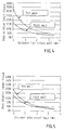
- Figure 4 shows in a graph the difference in absorbed dose in vessel wall vs. distance into the vessel wall for a square X-ray source structure where the dose is normalized to 100% at 0.7mm for thick wall.
- Figure 5 shows in a graph the difference in absorbed dose in vessel wall vs. distance into the vessel wall for a hexagonal X-ray source structure where the dose is normalized to 100% at 0.7mm for thick wall.
- Figure 1a schematically illustrates a miniature X-ray source in a cross-section, generally designated with reference numeral 2. It comprises a support structure 4 in which an X-ray cavity 6, provided with vacuum, is defined by an anode 10 and a cathode 8 at opposite sides of the cavity. The anode is connected to the positive pole of a high voltage source (not shown), and the cathode is connected to the negative pole.
- FIG 1b the device of figure 1a is shown schematically from above. As can be seen it has a square outer shape. This comes from the standard manufacturing techniques used in semiconductor technology. Namely, starting from a e.g.
- circular wafer 12 of a suitable material see figure 1c
- processing the wafer according to a number of process steps such as lithographic methods, etching, deposition etc, to comprise a large number of discrete elements, schematically indicated by reference numeral 14.
- sawing along the lines 16 indicated in figure 1c cuts out each element.
- the radiation strength depends upon the level of attenuation in the support structure.
- the attenuation depends, among other things e.g. the material of the structure, and the distance from the center of the X-ray source the radiation has to travels through the support structure.
- Figure 1b schematically illustrates different distances X1 and X2 in a square-shaped support structure resulting in a lower radiation dose beeing delivered in the direction of X1 than in the direction of X2 due to the higher radiation attenuation in direction X1.
- alumina polycrystalline Al 2 O 3
- sapphire crystalline Al 2 O 3
- pyrolytic or cubic boron nitride BN
- SiO 2 quarts
- the thickness of the material must be dimensioned taking account the thinnest part of the structure.
- Pyrolytic boron nitride is advantageous with regard to that it has an acceptable electrical break-through voltage. It is especially advantageous to choose a material having an intrinsic crystal structure that is the same as the cross-sectional shape of the support structure. Both pyrolytic boron nitride and sapphire have a hexagonal crystal structure and by dividing the wafer in hexagonal-shaped structures in the directions that correspond to the crystal structure the intrinsic material characteristics are optimally used.
- a uniformly distributed radiation around the X-ray source is desired, i.e. having essentially the same level of radiation in each direction in a plane perpendicular to the direction of a through-going hole in the support structure.
- the ideal cross-sectional shape of the cavity is circular and the cross-sectional shape of the support structure is also circular. These circles are concentric.
- Figures 2a and 3 show two different alternative shapes of the cross-section of support structure that may be obtained by straight-line divisions of a wafer.
- the holes made in the wafer to provide the X-ray source cavities may be achieved in two principally different ways.
- the cross-section of the cavity is to have a circular shape
- the most convenient method is to provide a wafer of a suitable material, e.g. alumina, and to make holes by laser drilling.
- Figure 2a shows a part of a wafer 18 having holes 20 made by laser drilling.
- cathodes 22 and anodes 24 can be mounted in the holes by a suitable bonding method or soldering, see figure 2b, which is a cross-section through the wafer in figure 2a.
- the wafer is divided as shown in figure 2a along lines 21 in order to provide X-ray sources having a hexagonal cross-section.
- the cross-section of the cavity is to have a polygonal shape, e.g. hexagonal or octagonal, the holes are made already when the wafer is manufactured.
- a positive mold is provided, having protrusions of the desired geometry (polygonal, e.g. octagonal or hexagonal).
- a ceramic paste is spread on the mold and exposed to sintering conditions.
- the wafer When the mold is removed the wafer will be provided with holes of the desired geometry.
- the wafer may be precision machined (e.g. by drilling, milling etc.) before sintering.
- anode and cathode structures are mounted in the holes so as to seal the cavity, and the wafer is divided to produce the hexagonal shaped support structures.
- the anode and cathode structures may also be made as structures on entire wafers, if properly designed with respect to for instance thermally induced stress.
- the dividing pattern will be as shown in figure 3. Obviously this dividing pattern will yield much more waste material, but it may be justified by the shape obtainable being somewhat better suited for the purpose of uniform radiation distribution than the hexagonal dividing pattern.
- the X-ray source is completed as follows.
- the cavity must be evacuated, which can be achieved with methods known in the art such as by employing evacuation channels and getter materials, and will not be further discussed herein.
- the individual elements are embedded in a polymer by an injection molding technique, so as to form a "bucket" of plastic around the element.
- the mold has a cylindrical shape so as to produce an X-ray source having a generally tubular shape, which is most suitable for insertion into blood vessels which have a generally tubular geometry.
- any shape can be made if desired.
- a minimum support structure wall thickness of 200 ⁇ m has been used, because it has to be thick enough to be mechanically stable (not to break) and has to be vacuum tight enough. Thinner walls are possible but will be more brittle and more sensitive to gas permeation.
- the structure is assumed to fit into a 1.5 mm. diameter circle.
- Mass attenuation data are taken from the National Institute of Standards and Technology. A typical vessel diameter of 3 mm. has been used, assuming a centered source. The radiation has been assumed to be a brehmsstrahlung spectra energized at 20 kV.
- EXAMPLE 1 (Calculation of absorbed dose from a square geometry element in a 3 mm vessel, in different directions):
- Figure 4 shows the difference in absorbed dose in a graph.
- EXAMPLE 2 (Calculation of absorbed dose from a hexagonal geometry element in a 3 mm vessel, in different directions):
- Figure 5 shows the difference in absorbed dose in a graph.
- the treatment time will be 42% longer when using a square geometry, as compared to a hexagonal geometry.
- the presumption is that a non-uniformly radiation distribution from the X-ray source is desired. This may e.g. be the case if an identified treatment site is located at one side of a blood vessel.
- a radiation window may be arranged that exhibits the highest radiation dose. This is achieved by varying the thickness of the support structure wall such that the smallest thickness is arranged where the highest radiation dose is desired, and thereby defining the position of the radiation window, and the largest thickness is arranged where the highest attenuation is wanted.
Landscapes
- Health & Medical Sciences (AREA)
- Engineering & Computer Science (AREA)
- Biomedical Technology (AREA)
- Life Sciences & Earth Sciences (AREA)
- Nuclear Medicine, Radiotherapy & Molecular Imaging (AREA)
- Radiology & Medical Imaging (AREA)
- Pathology (AREA)
- Animal Behavior & Ethology (AREA)
- General Health & Medical Sciences (AREA)
- Public Health (AREA)
- Veterinary Medicine (AREA)
- X-Ray Techniques (AREA)
- Apparatus For Radiation Diagnosis (AREA)
Applications Claiming Priority (2)
| Application Number | Priority Date | Filing Date | Title |
|---|---|---|---|
| US24672300P | 2000-11-09 | 2000-11-09 | |
| US246723P | 2000-11-09 |
Publications (2)
| Publication Number | Publication Date |
|---|---|
| EP1205217A2 true EP1205217A2 (de) | 2002-05-15 |
| EP1205217A3 EP1205217A3 (de) | 2004-01-02 |
Family
ID=22931927
Family Applications (1)
| Application Number | Title | Priority Date | Filing Date |
|---|---|---|---|
| EP01200594A Withdrawn EP1205217A3 (de) | 2000-11-09 | 2001-02-19 | Struktur einer miniaturisierten Röntgenstrahlungsquelle |
Country Status (2)
| Country | Link |
|---|---|
| US (1) | US6658088B2 (de) |
| EP (1) | EP1205217A3 (de) |
Families Citing this family (14)
| Publication number | Priority date | Publication date | Assignee | Title |
|---|---|---|---|---|
| EP1205216A3 (de) * | 2000-11-09 | 2004-01-02 | Radi Medical Technologies AB | Isolationsstruktur einer miniaturisierten Röntgenstrahlungsquelle |
| US6875165B2 (en) | 2001-02-22 | 2005-04-05 | Retinalabs, Inc. | Method of radiation delivery to the eye |
| NL1024109C2 (nl) * | 2003-08-14 | 2005-02-15 | Framatome Connectors Int | Ferrulesamenstel voor optische fibers. |
| US7280636B2 (en) * | 2003-10-03 | 2007-10-09 | Illinois Institute Of Technology | Device and method for producing a spatially uniformly intense source of x-rays |
| EP2298412A1 (de) | 2004-02-12 | 2011-03-23 | Neovista, Inc. | Vorrichtung für die intraokulare Brachytherapie |
| US7563222B2 (en) * | 2004-02-12 | 2009-07-21 | Neovista, Inc. | Methods and apparatus for intraocular brachytherapy |
| BRPI0618677A2 (pt) | 2005-11-15 | 2011-09-06 | Neovista Inc | métodos e aparelho para braquiterapia intra-ocular |
| JP4559490B2 (ja) * | 2005-12-22 | 2010-10-06 | パイオニア株式会社 | 光記録媒体 |
| US9324535B2 (en) * | 2006-02-16 | 2016-04-26 | Stellarray, Incorporaated | Self contained irradiation system using flat panel X-ray sources |
| US20100189223A1 (en) * | 2006-02-16 | 2010-07-29 | Steller Micro Devices | Digitally addressed flat panel x-ray sources |
| US20100189222A1 (en) * | 2006-02-16 | 2010-07-29 | Steller Micro Devices | Panoramic irradiation system using flat panel x-ray sources |
| US20070189459A1 (en) * | 2006-02-16 | 2007-08-16 | Stellar Micro Devices, Inc. | Compact radiation source |
| WO2009149175A1 (en) | 2008-06-04 | 2009-12-10 | Neovista, Inc. | Handheld radiation delivery system for advancing a radiation source wire |
| US12383246B2 (en) | 2020-10-12 | 2025-08-12 | Abbott Cardiovascular Systems, Inc. | Vessel closure device with improved safety and tract hemostasis |
Citations (2)
| Publication number | Priority date | Publication date | Assignee | Title |
|---|---|---|---|---|
| US5854822A (en) | 1997-07-25 | 1998-12-29 | Xrt Corp. | Miniature x-ray device having cold cathode |
| US5984853A (en) | 1997-02-25 | 1999-11-16 | Radi Medical Systems Ab | Miniaturized source of ionizing radiation and method of delivering same |
Family Cites Families (11)
| Publication number | Priority date | Publication date | Assignee | Title |
|---|---|---|---|---|
| US4426722A (en) * | 1981-03-12 | 1984-01-17 | Bell Telephone Laboratories, Incorporated | X-Ray microbeam generator |
| US4958365A (en) * | 1981-10-21 | 1990-09-18 | Elscint Ltd. | Medical imaging device using triggered plasma cathode flash X-ray source |
| US5428658A (en) * | 1994-01-21 | 1995-06-27 | Photoelectron Corporation | X-ray source with flexible probe |
| DE19639243C2 (de) * | 1996-09-24 | 1998-07-02 | Siemens Ag | Multi-, insbesondere dichromatische Röntgenquelle |
| IL129609A0 (en) * | 1996-11-01 | 2000-02-29 | Miley George H | Spherical inertial electrostatic confinement device as a tunable x-ray source |
| EP0860181B1 (de) * | 1997-02-21 | 2004-04-28 | Medtronic Ave, Inc. | Röntgenvorrichtung versehen mit einer Dehnungsstruktur zur lokalen Bestrahlung des Inneren eines Körpers |
| US6148061A (en) * | 1997-04-28 | 2000-11-14 | Newton Scientific, Inc. | Miniature x-ray unit |
| US6159140A (en) * | 1998-02-17 | 2000-12-12 | Advanced Cardiovascular Systems | Radiation shielded catheter for delivering a radioactive source and method of use |
| DE19828616A1 (de) * | 1998-06-26 | 2000-01-05 | Siemens Ag | Röntgenröhre und Katheter mit einer derartigen Röntgenröhre |
| US6064718A (en) * | 1998-09-29 | 2000-05-16 | The United States Of America As Represented By The Secretary Of The Navy | Field emission tube for a mobile X-ray unit |
| US6353658B1 (en) * | 1999-09-08 | 2002-03-05 | The Regents Of The University Of California | Miniature x-ray source |
-
2001
- 2001-02-19 EP EP01200594A patent/EP1205217A3/de not_active Withdrawn
- 2001-02-26 US US09/792,072 patent/US6658088B2/en not_active Expired - Fee Related
Patent Citations (2)
| Publication number | Priority date | Publication date | Assignee | Title |
|---|---|---|---|---|
| US5984853A (en) | 1997-02-25 | 1999-11-16 | Radi Medical Systems Ab | Miniaturized source of ionizing radiation and method of delivering same |
| US5854822A (en) | 1997-07-25 | 1998-12-29 | Xrt Corp. | Miniature x-ray device having cold cathode |
Also Published As
| Publication number | Publication date |
|---|---|
| US6658088B2 (en) | 2003-12-02 |
| EP1205217A3 (de) | 2004-01-02 |
| US20020054664A1 (en) | 2002-05-09 |
Similar Documents
| Publication | Publication Date | Title |
|---|---|---|
| EP1205217A2 (de) | Struktur einer miniaturisierten Röntgenstrahlungsquelle | |
| KR970000695B1 (ko) | 기판 및 박막의 표면을 고정밀 형상 가공하기 위해 플라즈마 에치 영역을 제한하기 위한 방법 및 장치 | |
| US6477233B1 (en) | Miniature x-ray source | |
| EP3791825B1 (de) | Vorrichtung zur oberflächenveränderung eines implantats | |
| JP4666448B2 (ja) | 中空カソードを含むプラズマドーピングシステム。 | |
| US9881819B2 (en) | Thermal processing apparatus for heating substrate, and susceptor | |
| KR102123889B1 (ko) | 기판유지장치 및 그 제조방법 | |
| KR101066173B1 (ko) | 샤워 플레이트의 제조 방법, 샤워 플레이트 및 플라즈마 처리 장치 | |
| JP2025072428A (ja) | ホローカソード放電抑制用に構成されたフローアパーチャを有するシャワーヘッドフェースプレート | |
| CN110225995A (zh) | 用于沉积、注入和处理的具有多种反应气体、高偏置功率和高功率脉冲源的pvd腔室的增设部分 | |
| CN1653207A (zh) | 用于衬底处理腔室的激光钻孔表面 | |
| CN1445811A (zh) | 溅射装置及其电极和该电极的制造方法 | |
| CN101203939B (zh) | 加工金刚石的方法以及利用金刚石半导体的器械 | |
| EP1215706A2 (de) | Elektronenstrahl-Behandlungsvorrichtung | |
| EP1520603B1 (de) | Festkörper-Applikator zur Brachytherapie | |
| CN114945534B (zh) | 气密封闭的透明的凹腔及其封壳 | |
| JP2017092095A (ja) | 熱処理装置 | |
| US7149282B2 (en) | X-ray tube electrodes | |
| TW201233516A (en) | Method of implanting and template apparatus | |
| EP1205216A2 (de) | Isolationsstruktur einer miniaturisierten Röntgenstrahlungsquelle | |
| JP2004247443A (ja) | 半導体ウエーハの加工方法 | |
| JP2006140230A (ja) | レーザ照射装置及びレーザ照射方法 | |
| US5894133A (en) | Sputter cathode for application of radioactive material | |
| CN217361495U (zh) | 一种调节离子刻蚀均匀性的孔丁 | |
| KR102374482B1 (ko) | 반도체 제조 장치 |
Legal Events
| Date | Code | Title | Description |
|---|---|---|---|
| PUAI | Public reference made under article 153(3) epc to a published international application that has entered the european phase |
Free format text: ORIGINAL CODE: 0009012 |
|
| AK | Designated contracting states |
Kind code of ref document: A2 Designated state(s): AT BE CH CY DE DK ES FI FR GB GR IE IT LI LU MC NL PT SE TR |
|
| AX | Request for extension of the european patent |
Free format text: AL;LT;LV;MK;RO;SI |
|
| PUAL | Search report despatched |
Free format text: ORIGINAL CODE: 0009013 |
|
| AK | Designated contracting states |
Kind code of ref document: A3 Designated state(s): AT BE CH CY DE DK ES FI FR GB GR IE IT LI LU MC NL PT SE TR |
|
| AX | Request for extension of the european patent |
Extension state: AL LT LV MK RO SI |
|
| AKX | Designation fees paid | ||
| REG | Reference to a national code |
Ref country code: DE Ref legal event code: 8566 |
|
| STAA | Information on the status of an ep patent application or granted ep patent |
Free format text: STATUS: THE APPLICATION IS DEEMED TO BE WITHDRAWN |
|
| 18D | Application deemed to be withdrawn |
Effective date: 20040703 |