EP1205256B1 - Ensemble de valves de changement de couleur et son procédé de commande - Google Patents
Ensemble de valves de changement de couleur et son procédé de commande Download PDFInfo
- Publication number
- EP1205256B1 EP1205256B1 EP01126211A EP01126211A EP1205256B1 EP 1205256 B1 EP1205256 B1 EP 1205256B1 EP 01126211 A EP01126211 A EP 01126211A EP 01126211 A EP01126211 A EP 01126211A EP 1205256 B1 EP1205256 B1 EP 1205256B1
- Authority
- EP
- European Patent Office
- Prior art keywords
- paint
- valves
- colour change
- valve arrangement
- change valve
- Prior art date
- Legal status (The legal status is an assumption and is not a legal conclusion. Google has not performed a legal analysis and makes no representation as to the accuracy of the status listed.)
- Expired - Lifetime
Links
- 238000000034 method Methods 0.000 title claims abstract description 6
- 239000003973 paint Substances 0.000 claims abstract description 40
- 239000011248 coating agent Substances 0.000 claims abstract description 8
- 238000000576 coating method Methods 0.000 claims abstract description 8
- 239000000463 material Substances 0.000 claims abstract description 6
- 239000003086 colorant Substances 0.000 claims description 6
- 238000011010 flushing procedure Methods 0.000 claims description 6
- 238000007789 sealing Methods 0.000 claims description 3
- 239000003795 chemical substances by application Substances 0.000 claims 2
- 238000004140 cleaning Methods 0.000 abstract 4
- 238000009434 installation Methods 0.000 description 4
- 238000010276 construction Methods 0.000 description 3
- 230000001934 delay Effects 0.000 description 2
- 238000009423 ventilation Methods 0.000 description 2
- 239000004020 conductor Substances 0.000 description 1
- 239000003599 detergent Substances 0.000 description 1
- 238000009503 electrostatic coating Methods 0.000 description 1
- 238000005516 engineering process Methods 0.000 description 1
- 238000004880 explosion Methods 0.000 description 1
- 210000000056 organ Anatomy 0.000 description 1
- 238000010422 painting Methods 0.000 description 1
- 238000005406 washing Methods 0.000 description 1
Images
Classifications
-
- B—PERFORMING OPERATIONS; TRANSPORTING
- B05—SPRAYING OR ATOMISING IN GENERAL; APPLYING FLUENT MATERIALS TO SURFACES, IN GENERAL
- B05B—SPRAYING APPARATUS; ATOMISING APPARATUS; NOZZLES
- B05B12/00—Arrangements for controlling delivery; Arrangements for controlling the spray area
- B05B12/14—Arrangements for controlling delivery; Arrangements for controlling the spray area for supplying a selected one of a plurality of liquids or other fluent materials or several in selected proportions to a spray apparatus, e.g. to a single spray outlet
- B05B12/149—Arrangements for controlling delivery; Arrangements for controlling the spray area for supplying a selected one of a plurality of liquids or other fluent materials or several in selected proportions to a spray apparatus, e.g. to a single spray outlet characterised by colour change manifolds or valves therefor
Definitions
- the invention relates to a color change valve arrangement for connecting a number of color lines for coating material selectable different colors with an application organ according to the preamble of claim 1 and a method for controlling such an arrangement.
- Farb rectifentilanssenen or short color changer allow in paint shops for coating workpieces such as motor vehicles during the Lackier horrends a rapid change from one color to another and consist mainly of a number of controllable color valves, which are distributed along a common color channels all colors. To adapt to the particular system and the number of selectable colors, they are in block construction of individual modules (terminal blocks, terminal strips, control heads) formed, which can be strung together, so that a variable, subsequently enlargeable or reducible number of connections for color cables can be realized. In addition to the paint valves, other similarly constructed valves for flushing media such as thinner and pulse air are usually provided.
- Known color changers of this type ( DÜRR, Technical Manual, Introduction to Passenger Car Painting Technology, April 1999 ) contain pneumatically controlled valves, which are actuated by compressed air signals from the valves individually assigned hoses. These control air hoses come from a remote pneumatic cabinet in which they are each a solenoid valve under Control of the electronic control system of the system for generating the compressed air control signals are opened and closed.
- the well-known pneumatic control system is very complicated, since for each switching function, a compressed air hose must be routed from the pneumatic cabinet in the color changer and in addition to each valve of the color changer a structurally and spatially separate external solenoid valve is needed. Furthermore, resulting from the control air hoses and the requirement of their ventilation and switching delays, which are also different lengths, since there are different hose lengths and correspondingly different switching times depending on the installation case (eg side and roof machines) within a plant. Short and precisely defined switching times are important, inter alia, in newer rinse programs for color changers, in which the opening times of the rinsing valves can typically be in the order of a fraction of a second ( DE 199 51 956 ).
- the object of the invention is to provide a color changer and a method for its control, which avoid the line overhead and the switching time delays pneumatically controlled color changer without the need of undesirably strong electromagnets.
- the installation effort is also reduced by the fact that only electrical lines are connected to the color changer except the common compressed air hose for all pneumatic valves, in the preferred data bus control only this bus and a power supply line for the electromagnets and for the electronic control circuits of the valves.
- the invention has the advantage that the pure pneumatic valves of the currently customary color changer can be easily replaced without any other structural changes by the new electrically controlled valves.
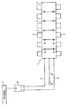
- the drawing shows schematically an electronically controlled by a fieldbus system color changer with pneumatic valves.
- the color changer 1 consists in the manner known per se of a modularly expandable or reducible group of juxtaposed block units, each consisting of housing bodies 2 and therein for the connection of the paint and flushing lines (not shown) with the central color channel mounted, eg screwed valves 3 exist.
- the valves 3 are controlled by a solenoid valve pneumatic valves. Suitable constructions for this purpose are available to the skilled person depending on the application.
- the compressed air is the control signal for opening and closing the paint valve
- the compressed air connection is replaced by an electromagnetic valve unit, which is attached to the pneumatic base unit and electrically the connection between a permanently under continuous pressure compressed air line 4 and the pneumatic base unit opens and closes.
- the attached electromagnetic valve unit may be constructed similar to the known per se pneumatic basic unit and, for example, contain a like the needle movable magnetic core on which a sealing seat is located. When the magnetic core is attracted by an electrical coil surrounding it, the sealing seat opens and releases the path of compressed air from the conduit 4 into the pneumatic base unit.
- a central pilot air source compressed air line 4 passes through the housing body 2 of the color changer 1 and is connected to all valves 3 within the color changer.
- an electrically controlled valve for opening and closing the pneumatic lines of the color and detergent valves can be used.
- the switching position of the valve can be displayed by an additional sensor per valve and / or be reported back to the electronic control system.
- an internal data bus 5 passed through all modular housing bodies 2 is preferably used, which may be a CAN bus or one of the other known standardized bus systems and which is connected via an interface 6 to the superordinate electronic control system 7 is. It is expedient to use one of the modern fieldbus systems whose binary control data in the color changer 1 are assigned to the valves 3 for which they are respectively intended.
- the modular block units formed in each case from one of the housing body 2 and one or more valves 3 can simply be plugged together to adapt to the respectively required number of selectable colors, the required cohesion being ensured by suitable locking means.
- the extending through the modular housing units sections of the internal data bus 5 are each connected by plug contacts 9 with each other. The same applies to the corresponding sections of the power supply line 8 and the compressed air line. 4
- the housing parts of the color changer 1 may consist of electrically conductive material, for example of conductive plastic.
Landscapes
- Spray Control Apparatus (AREA)
- Vehicle Body Suspensions (AREA)
- Magnetically Actuated Valves (AREA)
- Crystals, And After-Treatments Of Crystals (AREA)
- Coating Apparatus (AREA)
- Nozzles (AREA)
Claims (8)
- Ensemble de vannes de changement de couleur destiné à relier une pluralité de conduites d'amenée de peinture pour un matériau de revêtement de différentes couleurs sélectionnables
avec un dispositif d'application, avec un conduit d'amenée de peinture central pour le matériau de revêtement à acheminer vers le dispositif d'application,
avec des vannes (3) pilotables, qui sont raccordées au conduit d'amenée de peinture, pour les peintures sélectionnables et, le cas échéant, pour les nettoyants, et
avec un dispositif de commande pour activer les vannes (3), lequel peut être relié à un système de commande (7) électronique externe,
l'ensemble de vannes de changement de couleur (1) étant formé par des blocs modulaires, qui sont constitués chacun d'un corps de boîtier (2) et d'au moins une des vannes (3), et
les vannes (3) de l'ensemble de vannes de changement de couleur (1) étant munies de vannes électromagnétiques qui peuvent être reliées au système de commande (7) électronique externe via un système de raccordement électrique contenu dans l'ensemble de vannes de changement de couleur (1),
caractérisé en ce que dans les trajets de peinture ou les trajets de nettoyant guidées dans le conduit d'amenée de peinture sont montées respectivement des vannes pneumatiques qui s'ouvrent et se ferment au moyen d'air comprimé ou d'un autre gaz sous pression acheminé à partir d'une conduite de gaz sous pression (4) commune guidée à travers les corps de boîtier de l'ensemble de vannes de changement de couleur (1) vers toutes les vannes (3), et en ce que, à l'intérieur de l'ensemble de vannes de changement de couleur (1), respectivement une vanne électromagnétique est montée dans le trajet du gaz sous pression de la vanne pneumatique. - Ensemble de vannes de changement de couleur selon la revendication 1,
caractérisé en ce qu'à travers l'ensemble de vannes de changement de couleur (1) passe un bus de données (5) pour les données de commande numériques, lequel est couplé aux vannes (3) électromagnétiques par l'intermédiaire d'un circuit électronique. - Ensemble de vannes de changement de couleur selon la revendication 2, caractérisé en ce que chaque vanne (3) électromagnétique contient un circuit de commande électronique.
- Ensemble de vannes de changement de couleur selon la revendication 2 ou 3, caractérisé en ce que les vannes (3) électromagnétiques sont montées dans ou sur des corps de boîtier (2) enfichables, qui peuvent être alignés et à travers lesquels passe respectivement une partie du bus de données (5), et en ce que les parties du bus de données des différents modules sont reliées entre elles par des contacts à fiches (9).
- Ensemble de vannes de changement de couleur selon la revendication 4, caractérisé en ce que respectivement un tronçon d'une ligne d'alimentation en courant (8) pour les vannes (3) électromagnétiques et/ou de la conduite de gaz sous pression (4) passe à travers les modules et ces tronçons sont reliés entre eux par des contacts à fiches.
- Vanne pour un ensemble de vannes de changement de couleur selon la revendication 1, avec une partie de vanne pneumatique, qui contient un pointeau, dont une extrémité formant une surface d'étanchéité est poussée par un ressort dans une position de fermeture, dans laquelle ledit pointeau ferme le trajet de la peinture ou le trajet du nettoyant passant à travers le conduit d'amenée de peinture, et, pour ouvrir ce trajet, peut être soulevé à l'encontre de la force du ressort par l'air comprimé, qui sollicite un piston du pointeau lors de l'ouverture d'un trajet d'air comprimé, caractérisé en ce que sur la partie de vanne pneumatique est rapportée une vanne électromagnétique avec un siège de vanne à travers lequel passe le trajet d'air comprimé vers le piston de la partie de vanne pneumatique.
- Procédé de commande d'un ensemble de vannes de changement de couleur destiné à relier une pluralité de conduites d'amenée de peinture pour un matériau de revêtement de différentes couleurs sélectionnables avec un dispositif d'application,
sachant que des vannes (3), raccordées à un conduit d'amenée de peinture central, pour le matériau de revêtement et, le cas échéant, pour le nettoyant s'ouvrent et se ferment par voie pneumatique sous l'effet de l'air comprimé ou d'un autre gaz sous pression acheminé à partir d'une conduite de gaz sous pression (4), et l'ensemble de vannes de changement de couleur (1) étant formé par des blocs modulaires, qui sont constitués chacun d'un corps de boîtier (2) et d'au moins une des vannes (3), caractérisé en ce que la conduite de gaz sous pression (4), guidée à travers les corps de boîtier (2) de l'ensemble de vannes de changement de couleur (1) et commune à toutes les vannes (3), est en permanence sous pression pour le pilotage pneumatique des vannes (3), et en ce que la liaison entre la conduite de gaz sous pression (4) et les vannes (3) s'ouvre ou se ferme au moyen des électroaimants commandés électriquement à l'intérieur de l'ensemble de vannes de changement de couleur (1). - Procédé selon la revendication 7, caractérisé en ce que l'ensemble de vannes de changement de couleur est commandé par un système de bus de terrain.
Applications Claiming Priority (2)
| Application Number | Priority Date | Filing Date | Title |
|---|---|---|---|
| DE10056259A DE10056259A1 (de) | 2000-11-14 | 2000-11-14 | Farbwechselventilanordnung und Verfahren zu ihrer Steuerung |
| DE10056259 | 2000-11-14 |
Publications (3)
| Publication Number | Publication Date |
|---|---|
| EP1205256A2 EP1205256A2 (fr) | 2002-05-15 |
| EP1205256A3 EP1205256A3 (fr) | 2004-12-08 |
| EP1205256B1 true EP1205256B1 (fr) | 2008-03-05 |
Family
ID=7663166
Family Applications (1)
| Application Number | Title | Priority Date | Filing Date |
|---|---|---|---|
| EP01126211A Expired - Lifetime EP1205256B1 (fr) | 2000-11-14 | 2001-11-05 | Ensemble de valves de changement de couleur et son procédé de commande |
Country Status (4)
| Country | Link |
|---|---|
| EP (1) | EP1205256B1 (fr) |
| AT (1) | ATE387967T1 (fr) |
| DE (2) | DE10056259A1 (fr) |
| ES (1) | ES2300299T3 (fr) |
Families Citing this family (1)
| Publication number | Priority date | Publication date | Assignee | Title |
|---|---|---|---|---|
| DE10142355A1 (de) | 2001-08-30 | 2003-03-20 | Duerr Systems Gmbh | Beschichtungsanlage mit einem Regelkreis |
Family Cites Families (5)
| Publication number | Priority date | Publication date | Assignee | Title |
|---|---|---|---|---|
| FI882260L (fi) * | 1988-05-13 | 1989-11-14 | Saab Valmet Ab Oy | Faergbytes- och tvaettfoerfarande foer att anvaendas i en anordning foer utbredning av belaeggningsaemne, foerdelaktigt maolfaerg och anlaeggning foer anvaendning vid foerfarandet. |
| EP0480080A1 (fr) * | 1990-10-08 | 1992-04-15 | Trinity Industrial Corporation | Appareil de revêtement |
| DE4423643A1 (de) * | 1994-07-06 | 1996-01-11 | Ind Lackieranlagen Schmidt Gmb | Einrichtung zum Lackieren von Gegenständen mit verschiedenen Farben |
| DE19836604A1 (de) | 1998-08-12 | 2000-03-09 | Duerr Systems Gmbh | Ventilanordnung zur Steuerung des Materialflusses in einer Beschichtungsanlage |
| DE19951956A1 (de) | 1999-10-29 | 2001-06-13 | Duerr Systems Gmbh | Ventilanordnung und Verfahren zum Spülen eines Farbwechslers |
-
2000
- 2000-11-14 DE DE10056259A patent/DE10056259A1/de not_active Withdrawn
-
2001
- 2001-11-05 EP EP01126211A patent/EP1205256B1/fr not_active Expired - Lifetime
- 2001-11-05 AT AT01126211T patent/ATE387967T1/de not_active IP Right Cessation
- 2001-11-05 ES ES01126211T patent/ES2300299T3/es not_active Expired - Lifetime
- 2001-11-05 DE DE50113685T patent/DE50113685D1/de not_active Expired - Lifetime
Also Published As
| Publication number | Publication date |
|---|---|
| DE50113685D1 (de) | 2008-04-17 |
| EP1205256A2 (fr) | 2002-05-15 |
| DE10056259A1 (de) | 2002-05-23 |
| ES2300299T3 (es) | 2008-06-16 |
| ATE387967T1 (de) | 2008-03-15 |
| EP1205256A3 (fr) | 2004-12-08 |
Similar Documents
| Publication | Publication Date | Title |
|---|---|---|
| EP1013940B1 (fr) | Arrangement de soupape | |
| DE60301746T2 (de) | Pneumatikventilgruppe mit einfacher Installierung und einfacher Wartung | |
| DE4230414C2 (de) | Elektro-pneumatische Steuereinrichtung | |
| EP0608245A1 (fr) | Dispositif de commande electropneumatique. | |
| EP0487173A1 (fr) | Dispositif de commande pour fluides, en particulier pour air sous pression | |
| DE3337800A1 (de) | Mehrkreis-druckmittel-bremsanlage | |
| WO2008064755A1 (fr) | Ensemble de soupape | |
| EP0803653A1 (fr) | Système pneumatique de commande | |
| EP4185496B1 (fr) | Dispositif de nettoyage à canaux multiples, module de nettoyage de capteur à canaux multiples, véhicule | |
| EP3296602B1 (fr) | Dispositif de distribution de fluide | |
| EP0968372A1 (fr) | Base de montage en forme de plaque | |
| WO1996019027A1 (fr) | Dispositif de commande, notamment de commande de soupapes | |
| DE9310438U1 (de) | Ventilstation | |
| EP0629783B1 (fr) | ContrÔle combiné de valves pneumatiques et hydrauliques | |
| DE9211109U1 (de) | Elektro-pneumatische Steuereinrichtung | |
| EP0621407B1 (fr) | Ensemble valve | |
| EP1287900B1 (fr) | Installation de revêtement comprenant une boucle de régulation | |
| EP1251283B1 (fr) | Kit pour fabriquer un dispositif de contrôle fluidique | |
| EP0930130B1 (fr) | Dispositif de serrage | |
| DE10213397B4 (de) | Ventilanordnung | |
| EP1205256A2 (fr) | Ensemble de valves de changement de couleur et son procédé de commande | |
| DE3730778A1 (de) | Relaisventileinrichtung | |
| DE102004044497B3 (de) | Anschlussvorrichtung sowie damit ausgestattetes Ventil und Ventilbatterie | |
| DE3915827C1 (fr) | ||
| DE69700098T2 (de) | Elektro-pneumatischer Steuerkopf für Aktuatoren |
Legal Events
| Date | Code | Title | Description |
|---|---|---|---|
| PUAI | Public reference made under article 153(3) epc to a published international application that has entered the european phase |
Free format text: ORIGINAL CODE: 0009012 |
|
| AK | Designated contracting states |
Kind code of ref document: A2 Designated state(s): AT BE CH CY DE DK ES FI FR GB GR IE IT LI LU MC NL PT SE TR |
|
| AX | Request for extension of the european patent |
Free format text: AL;LT;LV;MK;RO;SI |
|
| PUAL | Search report despatched |
Free format text: ORIGINAL CODE: 0009013 |
|
| AK | Designated contracting states |
Kind code of ref document: A3 Designated state(s): AT BE CH CY DE DK ES FI FR GB GR IE IT LI LU MC NL PT SE TR |
|
| AX | Request for extension of the european patent |
Extension state: AL LT LV MK RO SI |
|
| 17P | Request for examination filed |
Effective date: 20050411 |
|
| AKX | Designation fees paid |
Designated state(s): AT BE CH CY DE DK ES FI FR GB GR IE IT LI LU MC NL PT SE TR |
|
| 17Q | First examination report despatched |
Effective date: 20070322 |
|
| GRAP | Despatch of communication of intention to grant a patent |
Free format text: ORIGINAL CODE: EPIDOSNIGR1 |
|
| GRAS | Grant fee paid |
Free format text: ORIGINAL CODE: EPIDOSNIGR3 |
|
| GRAA | (expected) grant |
Free format text: ORIGINAL CODE: 0009210 |
|
| AK | Designated contracting states |
Kind code of ref document: B1 Designated state(s): AT BE CH CY DE DK ES FI FR GB GR IE IT LI LU MC NL PT SE TR |
|
| REG | Reference to a national code |
Ref country code: GB Ref legal event code: FG4D Free format text: NOT ENGLISH |
|
| REG | Reference to a national code |
Ref country code: CH Ref legal event code: EP |
|
| REG | Reference to a national code |
Ref country code: IE Ref legal event code: FG4D Free format text: LANGUAGE OF EP DOCUMENT: GERMAN |
|
| REF | Corresponds to: |
Ref document number: 50113685 Country of ref document: DE Date of ref document: 20080417 Kind code of ref document: P |
|
| REG | Reference to a national code |
Ref country code: SE Ref legal event code: TRGR |
|
| REG | Reference to a national code |
Ref country code: ES Ref legal event code: FG2A Ref document number: 2300299 Country of ref document: ES Kind code of ref document: T3 |
|
| PG25 | Lapsed in a contracting state [announced via postgrant information from national office to epo] |
Ref country code: FI Free format text: LAPSE BECAUSE OF FAILURE TO SUBMIT A TRANSLATION OF THE DESCRIPTION OR TO PAY THE FEE WITHIN THE PRESCRIBED TIME-LIMIT Effective date: 20080305 |
|
| ET | Fr: translation filed | ||
| REG | Reference to a national code |
Ref country code: IE Ref legal event code: FD4D |
|
| PG25 | Lapsed in a contracting state [announced via postgrant information from national office to epo] |
Ref country code: PT Free format text: LAPSE BECAUSE OF FAILURE TO SUBMIT A TRANSLATION OF THE DESCRIPTION OR TO PAY THE FEE WITHIN THE PRESCRIBED TIME-LIMIT Effective date: 20080805 |
|
| PLBE | No opposition filed within time limit |
Free format text: ORIGINAL CODE: 0009261 |
|
| STAA | Information on the status of an ep patent application or granted ep patent |
Free format text: STATUS: NO OPPOSITION FILED WITHIN TIME LIMIT |
|
| PG25 | Lapsed in a contracting state [announced via postgrant information from national office to epo] |
Ref country code: IE Free format text: LAPSE BECAUSE OF FAILURE TO SUBMIT A TRANSLATION OF THE DESCRIPTION OR TO PAY THE FEE WITHIN THE PRESCRIBED TIME-LIMIT Effective date: 20080305 Ref country code: DK Free format text: LAPSE BECAUSE OF FAILURE TO SUBMIT A TRANSLATION OF THE DESCRIPTION OR TO PAY THE FEE WITHIN THE PRESCRIBED TIME-LIMIT Effective date: 20080305 |
|
| 26N | No opposition filed |
Effective date: 20081208 |
|
| PG25 | Lapsed in a contracting state [announced via postgrant information from national office to epo] |
Ref country code: MC Free format text: LAPSE BECAUSE OF NON-PAYMENT OF DUE FEES Effective date: 20081130 |
|
| REG | Reference to a national code |
Ref country code: CH Ref legal event code: PL |
|
| PG25 | Lapsed in a contracting state [announced via postgrant information from national office to epo] |
Ref country code: CY Free format text: LAPSE BECAUSE OF FAILURE TO SUBMIT A TRANSLATION OF THE DESCRIPTION OR TO PAY THE FEE WITHIN THE PRESCRIBED TIME-LIMIT Effective date: 20080305 |
|
| PG25 | Lapsed in a contracting state [announced via postgrant information from national office to epo] |
Ref country code: CH Free format text: LAPSE BECAUSE OF NON-PAYMENT OF DUE FEES Effective date: 20081130 Ref country code: LI Free format text: LAPSE BECAUSE OF NON-PAYMENT OF DUE FEES Effective date: 20081130 |
|
| PG25 | Lapsed in a contracting state [announced via postgrant information from national office to epo] |
Ref country code: AT Free format text: LAPSE BECAUSE OF NON-PAYMENT OF DUE FEES Effective date: 20081105 |
|
| PG25 | Lapsed in a contracting state [announced via postgrant information from national office to epo] |
Ref country code: LU Free format text: LAPSE BECAUSE OF NON-PAYMENT OF DUE FEES Effective date: 20081105 |
|
| PG25 | Lapsed in a contracting state [announced via postgrant information from national office to epo] |
Ref country code: TR Free format text: LAPSE BECAUSE OF FAILURE TO SUBMIT A TRANSLATION OF THE DESCRIPTION OR TO PAY THE FEE WITHIN THE PRESCRIBED TIME-LIMIT Effective date: 20080305 |
|
| PG25 | Lapsed in a contracting state [announced via postgrant information from national office to epo] |
Ref country code: GR Free format text: LAPSE BECAUSE OF FAILURE TO SUBMIT A TRANSLATION OF THE DESCRIPTION OR TO PAY THE FEE WITHIN THE PRESCRIBED TIME-LIMIT Effective date: 20080606 |
|
| PGFP | Annual fee paid to national office [announced via postgrant information from national office to epo] |
Ref country code: DE Payment date: 20131121 Year of fee payment: 13 Ref country code: FR Payment date: 20131120 Year of fee payment: 13 Ref country code: SE Payment date: 20131121 Year of fee payment: 13 Ref country code: GB Payment date: 20131120 Year of fee payment: 13 |
|
| PGFP | Annual fee paid to national office [announced via postgrant information from national office to epo] |
Ref country code: IT Payment date: 20131125 Year of fee payment: 13 Ref country code: ES Payment date: 20131128 Year of fee payment: 13 Ref country code: BE Payment date: 20131121 Year of fee payment: 13 Ref country code: NL Payment date: 20131121 Year of fee payment: 13 |
|
| REG | Reference to a national code |
Ref country code: DE Ref legal event code: R119 Ref document number: 50113685 Country of ref document: DE |
|
| REG | Reference to a national code |
Ref country code: NL Ref legal event code: V1 Effective date: 20150601 |
|
| PG25 | Lapsed in a contracting state [announced via postgrant information from national office to epo] |
Ref country code: BE Free format text: LAPSE BECAUSE OF NON-PAYMENT OF DUE FEES Effective date: 20141130 |
|
| REG | Reference to a national code |
Ref country code: SE Ref legal event code: EUG |
|
| GBPC | Gb: european patent ceased through non-payment of renewal fee |
Effective date: 20141105 |
|
| PG25 | Lapsed in a contracting state [announced via postgrant information from national office to epo] |
Ref country code: SE Free format text: LAPSE BECAUSE OF NON-PAYMENT OF DUE FEES Effective date: 20141106 |
|
| REG | Reference to a national code |
Ref country code: FR Ref legal event code: ST Effective date: 20150731 |
|
| PG25 | Lapsed in a contracting state [announced via postgrant information from national office to epo] |
Ref country code: NL Free format text: LAPSE BECAUSE OF NON-PAYMENT OF DUE FEES Effective date: 20150601 |
|
| PG25 | Lapsed in a contracting state [announced via postgrant information from national office to epo] |
Ref country code: DE Free format text: LAPSE BECAUSE OF NON-PAYMENT OF DUE FEES Effective date: 20150602 Ref country code: GB Free format text: LAPSE BECAUSE OF NON-PAYMENT OF DUE FEES Effective date: 20141105 |
|
| PG25 | Lapsed in a contracting state [announced via postgrant information from national office to epo] |
Ref country code: FR Free format text: LAPSE BECAUSE OF NON-PAYMENT OF DUE FEES Effective date: 20141201 |
|
| PG25 | Lapsed in a contracting state [announced via postgrant information from national office to epo] |
Ref country code: IT Free format text: LAPSE BECAUSE OF NON-PAYMENT OF DUE FEES Effective date: 20141105 |
|
| REG | Reference to a national code |
Ref country code: ES Ref legal event code: FD2A Effective date: 20160104 |
|
| PG25 | Lapsed in a contracting state [announced via postgrant information from national office to epo] |
Ref country code: ES Free format text: LAPSE BECAUSE OF NON-PAYMENT OF DUE FEES Effective date: 20141106 |