EP1205305B1 - Imprimante assistée à éjection à la demande de gouttes d'encre avec micro-actionneur déformable - Google Patents
Imprimante assistée à éjection à la demande de gouttes d'encre avec micro-actionneur déformable Download PDFInfo
- Publication number
- EP1205305B1 EP1205305B1 EP01204150A EP01204150A EP1205305B1 EP 1205305 B1 EP1205305 B1 EP 1205305B1 EP 01204150 A EP01204150 A EP 01204150A EP 01204150 A EP01204150 A EP 01204150A EP 1205305 B1 EP1205305 B1 EP 1205305B1
- Authority
- EP
- European Patent Office
- Prior art keywords
- ink
- elastomer material
- deformable elastomer
- print head
- micro
- Prior art date
- Legal status (The legal status is an assumption and is not a legal conclusion. Google has not performed a legal analysis and makes no representation as to the accuracy of the status listed.)
- Expired - Lifetime
Links
Images


Classifications
-
- B—PERFORMING OPERATIONS; TRANSPORTING
- B41—PRINTING; LINING MACHINES; TYPEWRITERS; STAMPS
- B41J—TYPEWRITERS; SELECTIVE PRINTING MECHANISMS, i.e. MECHANISMS PRINTING OTHERWISE THAN FROM A FORME; CORRECTION OF TYPOGRAPHICAL ERRORS
- B41J2/00—Typewriters or selective printing mechanisms characterised by the printing or marking process for which they are designed
- B41J2/005—Typewriters or selective printing mechanisms characterised by the printing or marking process for which they are designed characterised by bringing liquid or particles selectively into contact with a printing material
- B41J2/01—Ink jet
- B41J2/135—Nozzles
- B41J2/14—Structure thereof only for on-demand ink jet heads
- B41J2/14427—Structure of ink jet print heads with thermal bend detached actuators
-
- B—PERFORMING OPERATIONS; TRANSPORTING
- B41—PRINTING; LINING MACHINES; TYPEWRITERS; STAMPS
- B41J—TYPEWRITERS; SELECTIVE PRINTING MECHANISMS, i.e. MECHANISMS PRINTING OTHERWISE THAN FROM A FORME; CORRECTION OF TYPOGRAPHICAL ERRORS
- B41J2/00—Typewriters or selective printing mechanisms characterised by the printing or marking process for which they are designed
- B41J2/005—Typewriters or selective printing mechanisms characterised by the printing or marking process for which they are designed characterised by bringing liquid or particles selectively into contact with a printing material
- B41J2/01—Ink jet
- B41J2/015—Ink jet characterised by the jet generation process
- B41J2/04—Ink jet characterised by the jet generation process generating single droplets or particles on demand
- B41J2002/043—Electrostatic transducer
Definitions
- This invention generally relates to a drop-on-demand inkjet printer having a droplet separator that includes a mechanism for assisting the selective generation of micro droplets of ink.
- Inkjet printing is a prominent contender in the digitally controlled electronic printing arena because, e.g., of its non-impact, low-noise characteristics, its use of plain paper, and its avoidance of toner transfers and fixing.
- Inkjet printing mechanisms can be categorized as either continuous inkjet or drop-on-demand inkjet.
- Drop-on-demand inkjet printers selectively eject droplets of ink toward a printing media to create an image.
- Such printers typically include a print head having an array of nozzles, each of which is supplied with ink. Each of the nozzles communicates with a chamber which can be pressurized in response to an electrical impulse to induce the generation of an ink droplet from the outlet of the nozzle.
- Many such printers use piezoelectric transducers to create the momentary pressure necessary to generate an ink droplet. Examples of such printers are present in U.S. Patent Nos. 4,646,106 and 5,739,832.
- piezoelectric transducers While such piezoelectric transducers are capable of generating the momentary pressures necessary for useful drop-on-demand printing, they are relatively difficult and expensive to manufacture since the piezoelectric crystals (which are formed from a brittle, ceramic material) must be micro-machined and precision installed behind the very small ink chambers connected to each of the inkjet nozzles of the printer. Additionally, piezoelectric transducers require relatively high voltage, high power electrical pulses to effectively drive them in such printers.
- each paddle would include two dissimilar metals and a heating element connected thereto.
- the difference in the coefficient of expansion between the two dissimilar metals causes them to momentarily curl in much the same action as a bimetallic thermometer, only much quicker.
- a paddle is attached to the dissimilar metals to convert momentary curling action of these metals into a compressive wave which effectively ejects a droplet of ink out of the nozzle outlet.
- WO-0055 089 A shows an ink jet head according to the preamble of claim 1 and a method according to the preamble of claim 10.
- thermal paddle transducers overcome the major disadvantages associated with piezoelectric transducers in that they are easier to manufacture and require less electrical power, they do not have the longevity of piezoelectric transducers. Additionally, thermal paddle transducers are prone to attracting dye deposit due to heat used in actuation. The dynamic response characteristics of the paddle will alter as dye deposit builds making the paddle unreliable for reproducible ink drop generation. Thermal paddle transducers therefore are preferably used with specially formulated inks that have additives to minimize heat-induced deposition and/or have lower dye content.
- a drop-on-demand inkjet print head includes a nozzle with an ink outlet, an ink supply channel through which a body of ink is supplied to the nozzle, and a member movable in the ink supply channel toward the nozzle outlet for causing a droplet to separate from the body of ink.
- a micro-actuator applies a mechanical force to the member.
- the micro-actuator includes a body of elastomer material having opposed first and second surfaces spaced apart in a first direction by a predetermined at-rest dimension.
- a charge mechanism is coupled to the first opposed surface of the elastomer material so as to apply an electrical charge in the first direction.
- the charge is spatially varied in a second direction substantially normal to the first direction so as to create spatially varied mechanical forces across the elastomer material such that the elastomer material exhibits spatially varied growth in the first direction.
- the member is associated with the second opposed surface of the elastomer material so as to move in the first direction in response to growth of the elastomer material.
- a print head 10 generally comprises a front substrate 11 having an outer surface 12 and a back substrate 13.
- a plurality of nozzles 14 are disposed through substrate 11.
- Each nozzle has lower, tapered side walls 15, and upper cylindrical side walls 16.
- An ink conducting channel 17 is provided between substrates 11 and 13 for providing a supply of liquid ink to the nozzles.
- Liquid ink forms a concave meniscus 18 around upper side walls 16 that define the nozzle outlet.
- Each nozzle 14 is provided with a member such as a mechanically-actuated paddle 19 in FIG. 1 directly below nozzle 14.
- the paddle is carried at one end of a cantilever beam 20 resting on a fulcrum 21.
- a pivotating mechanism may be used to support fulcrum 21.
- fulcrum 21 abuts a micro-actuator 22 which, as explained in detail below, can be caused to suddenly expand to push the end of cantilever beam 20 downwardly as illustrated in phantom lines in FIG. 1.
- Cantilever beam pivots about fulcrum 21, causing paddle 19 to move sharply upwardly toward nozzle 14.
- the shockwave that the motion of the paddle 19 transmits to the liquid ink inside nozzle 14 results in the formation and ejection of a micro droplet 23 of ink (shown in phantom) from print head 10.
- paddle 19 generally does not eject micro droplets 23 with sufficient speed and accuracy toward a printing medium (not shown).
- an optional droplet assistor illustrated as an annular heating element 24 that closely circumscribes nozzle 14, has been provided. Such a heating element may easily be integrated onto outer surface 12 of the print head by way of CMOS technology. When an electrical pulse is conducted through annular heating element 24, a momentary heat pulse reduces the surface tension of the ink in the vicinity of meniscus 18. Such heaters and the circuitry necessary to drive them are disclosed in commonly assigned U.S. patent application Serial No. 08/954,317 filed October 17, 1997. While optional droplet assistor is illustrated as annular heating element 24, it could for example be a surfactant supplier that operates to lower the surface tension of ink in the meniscus; or a combination of a heater and a surfactant supplier.
- micro droplets of ink are generated by simultaneously expanding micro-actuator 22 and activating heating element 24.
- paddle 19 immediately moves sharply into the position indicated in phantom while the heat pulse generated by annular heating element 24 lowers the surface tension of the ink in meniscus 18. The end result is that an ink droplet is expelled at a high velocity from the nozzle.
- the following configuration would produce a 3 picoliter droplet. Assuming that the diameter of paddle 19 is 30 ⁇ m and cantilever beam 20 is 200 ⁇ m long, when fulcrum 21 is 20 ⁇ m from the paddle end, a 0.05 ⁇ m movement causes paddle 19 to move 4.5 ⁇ m in the ink chamber. This produces a droplet slightly larger than 3 picoliters.
- a micro-actuator usable in the present invention includes a support substrate 32 having a first surface 34 and a second surface 35. Surfaces 34 and 35 of substrate 32 are essentially parallel planes separated by the thickness of substrate 32.
- the second surface of substrate 32 carries a body 38 of deformable elastomer material.
- Substrate 32 is stationary and establishes a rigid mechanical boundary with deformable elastomer body 38 at their interface.
- An electrically conductive flexible electrode plate 40 is attached to elastomer body 38.
- a rigid, essentially non-deformable member 41 overlies electrode plate 40, but is not attached to the electrode plate.
- a grille electrode structure 48 Affixed to first surface 34 of substrate 32 is a grille electrode structure 48.
- Structure 48 further includes a plurality of first conductive fingers 50. Adjacent fingers 50 are displaced by a first period 52. First period 52 is perpendicular to the thickness between the first and second surfaces of substrate 32.
- the drawings show grille electrode structure 48 on the outer surface of support substrate 32. Persons skilled in the art will understand that electrode structure may be attached to the inner surface of support substrate 32 so as to extend into elastomer body 38.
- Fingers 50 are electrically connected by a first buss 54.
- Structure 48 further includes a plurality of second conductive fingers 56. Adjacent fingers 56 are displaced by period 52. Fingers 56 are electrically connected by a second buss 58. Fingers 50 and fingers 56 are interwoven to create grille electrode structure 48.
- First buss 54 is electrically connected to a first voltage source 60.
- Second buss 58 is electrically connected to a second voltage source 62.
- Conductive metallic electrode plate 40 is electrically connected to a third voltage source 64.
- electrically connecting first buss 54 and second buss 58 to respective voltage sources and applying a voltage to conductive metallic electrode plate 40 allows a periodic electric field to be established in deformable elastomer body 38.
- Polarity and magnitude of the voltage sources are selected to be compatible with the resolution and speed of response requirements for the application under consideration.
- an electric field is established across deformable elastomer body 38 in a direction normal the planes of electrode structure 48 and electrode plate 40 by applying potential from sources 60 and 62 to busses 54 and 58, respectively. If the polarity of the grille electrode fingers and electrode plate 40 is different, the mechanical force of attraction between a finger and electrode plate 40 due to the electric field causes deformable elastomer layer to locally compress. Of course, a finger and electrode plate 40 will repulse and cause the elastomer layer to locally deform in expansion if like electrical poles are applied to a finger and electrode plate 40.
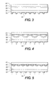
- FIG. 4 shows the situation where the polarities of sources 60 and 62 are different. Every other finger 50, 56 carries an opposite charge.
- Electrode plate 40 is alternately repelled and attracted to busses 54 and 58.
- FIG. 5 shows the situation where the polarities of sources 60 and 62 are the same, and are the same as that of electrode plate 40.
- Each finger 50, 56 repels an associated portion of electrode plate 40.
- Deformable elastomer body 38 may comprise any suitable elastomer material, such as for example natural rubber or synthetic polymers with rubber-like characteristics (silicone rubber, styrenebutadiene, polybutadiene, neoprene, butyl, polyisoprene, nitrile, urethane, polydimethylsioxane, and ethylene rubbers). Elastomers having relatively high dielectric strength will allow the devices to be operated at higher voltage levels, which in many instances may be preferred.
- Suitable selection of a particular elastomer material which exhibits an elastic modulus appropriate for a predetermined intended use is within ordinary skill given the description herein. For example, a relatively more stiff elastomer will typically recover more rapidly when an electric field is removed. On the other hand, an elastomer material having a relatively low elastic modulus is typically capable of greater deformations for a given value of electric field. The strain is negative indicating a compressive deformation.
- Electrode plate 40 should have good lateral conductivity, excellent stability, and little internal stress; as well as being highly adherent to deformable elastomer body 38. Suitable materials for electrode plate 40 include gold, silver, chromium, nickel, aluminum, conducting polymer, etc. Electrode plate 40 may be formed such as by chemical reaction, precipitation from a solution, electrophoresis, electrolysis, electroless plating, vapor deposition and others. The thickness of electrode plate 40 may, for example, be in the range of from about 200 angstroms to about 5,000 angstroms depending upon any desired flexibility, and the requisite strength and conductivity.
- Inhomogeneous electric fields will lead to electrostatic forces on deformable elastomer body 38.
- Inhomogeneous electric fields in deformable elastomer body 38 are related to the electrostatic forces applied to conductor 40.
- conductor 40 is carried by the second surface of deformable elastomer body 38. Varying electrostatic forces applied to conductor 40 varies deformation of the second surface of deformable elastomer body 38.
- the first surface of deformable elastomer body 38 is stationary and deformations of the second surface of deformable elastomer body 38 lead to thickness variations in deformable elastomer body 38. Thickness of deformable elastomer body 38 is utilized to characterize variations in separation between the first surface of deformable elastomer body 38 and its second surface.
- micro-actuator 22 has been illustrated, but it will be understood that the micro-actuator may take any of several known forms.
Landscapes
- Particle Formation And Scattering Control In Inkjet Printers (AREA)
Claims (10)
- Tête d'impression à jet d'encre particulièrement conçue pour générer des micro-gouttelettes à la demande, ladite tête d'impression comprenant :une buse avec un orifice de sortie d'encre,un canal d'alimentation en encre par l'intermédiaire duquel un corps d'encre liquide est fourni à ladite buse,un élément dans le canal d'alimentation en encre et mobile dans une direction allant vers l'orifice de sortie de buse pour amener une gouttelette d'encre à se séparer dudit corps d'encre, etun micro actionneur destiné à appliquer une force mécanique audit élément,
caractérisé en ce que ledit micro actionneur comprend :un corps de matériau élastomère déformable présentant des première et seconde surfaces opposées espacées l'une de l'autre dans une première direction par une première dimension au repos prédéterminée, etun mécanisme de charge relié à ladite première surface opposée dudit corps de matériau élastomère déformable, ledit mécanisme de charge étant conçu pour appliquer une charge électrique au travers dudit corps de matériau élastomère déformable dans ladite première direction, ladite charge variant dans l'espace dans une seconde direction sensiblement normale à ladite première direction de façon à créer des forces mécaniques variables dans l'espace au travers du corps de matériau élastomère déformable de sorte que ledit corps de matériau élastomère déformable présente une croissance variant dans l'espace dans ladite première direction, ledit élément étant associé à la seconde surface opposée du corps de matériau élastomère déformable de façon à se déplacer dans ladite première direction en réponse à la croissance du corps de matériau élastomère déformable. - Tête d'impression à jet d'encre telle que définie dans la revendication 1, dans laquelle ledit élément comprend une palette actionnée mécaniquement.
- Tête d'impression à jet d'encre telle que définie dans la revendication 2, dans laquelle ledit élément comprend un bras supportant ladite palette actionnée mécaniquement, dans laquelle une force appliquée au bras est transmise à la palette.
- Tête d'impression à jet d'encre telle que définie dans la revendication 3, dans laquelle ledit bras présente deux extrémités opposées et est supporté en vue d'une rotation autour d'une position intermédiaire à ses extrémités, ladite palette étant d'un côté de la position de support, et ledit micro actionneur étant de l'autre côté de ladite position de support.
- Tête d'impression à jet d'encre telle que définie dans la revendication 1, dans laquelle le mécanisme de charge comprend une électrode de grille pouvant être reliée à une source de potentiel électrique de façon à établir ladite charge électrique variant dans l'espace.
- Tête d'impression à jet d'encre telle que définie dans la revendication 5, dans laquelle le mécanisme de charge comprend en outre une couche flexible électriquement conductrice sur ladite seconde surface entre ladite seconde surface et ledit élément rigide, ladite couche flexible pouvant être reliée à une source de potentiel électrique de façon à induire une force entre la couche flexible et ladite électrode de grille lors de l'application d'un champ électrique.
- Tête d'impression à jet d'encre telle que définie dans la revendication 5, comprenant en outre un substrat rigide immobile entre la première surface et ladite électrode de grille afin d'établir une limite mécanique rigide au niveau de la première surface.
- Tête d'impression à jet d'encre telle que définie dans la revendication 1, comprenant en outre un élément d'assistance de gouttelettes relié au corps d'encre dans ladite buse afin de diminuer une quantité d'énergie nécessaire pour qu'une gouttelette d'encre se forme et se sépare du corps d'encre.
- Tête d'impression à jet d'encre telle que définie dans la revendication 8, dans laquelle ledit élément d'assistance de gouttelettes comprend un élément chauffant disposé à proximité dudit orifice de sortie de la buse, destiné à appliquer une impulsion de chaleur à l'encre dans ladite buse afin de diminuer la tension superficielle dudit ménisque d'encre.
- Procédé destiné à appliquer une force mécanique pour émettre des micro-gouttelettes depuis un orifice de sortie de buse de tête d'impression, ledit procédé comprenant :la fourniture d'un corps d'encre liquide par l'intermédiaire d'un canal, à l'orifice de sortie de buse, etl'utilisation d'un micro actionneur appliquant une force mécanique à un élément dans le canal afin de déplacer l'élément dans une direction allant vers l'orifice de sortie de la buse pour amener une gouttelette d'encre à se séparer dudit corps d'encré, caractérisé en ce que ledit micro actionneur comprend :un corps de matériau élastomère déformable présentant des première et seconde surfaces opposées espacées l'une de l'autre dans une première direction par une dimension au repos prédéterminée, etun mécanisme de charge relié à ladite première surface opposée dudit corps de matériau élastomère déformable, ledit mécanisme de charge étant conçu pour appliquer une charge électrique au travers dudit corps de matériau élastomère déformable dans ladite première direction, ladite charge variant dans l'espace dans une seconde direction sensiblement normale à ladite première direction de façon à créer des forces mécaniques variant dans l'espace au travers du corps de matériau élastomère déformable de sorte que ledit corps de matériau élastomère déformable présente une croissance variable dans l'espace dans ladite première direction, ledit élément étant associée à la seconde surface opposée du corps de matériau élastomère déformable de façon à se déplacer dans ladite première direction en réponse à la croissance du corps de matériau élastomère déformable.
Applications Claiming Priority (2)
| Application Number | Priority Date | Filing Date | Title |
|---|---|---|---|
| US09/708,354 US6352337B1 (en) | 2000-11-08 | 2000-11-08 | Assisted drop-on-demand inkjet printer using deformable micro-acuator |
| US708354 | 2000-11-08 |
Publications (2)
| Publication Number | Publication Date |
|---|---|
| EP1205305A1 EP1205305A1 (fr) | 2002-05-15 |
| EP1205305B1 true EP1205305B1 (fr) | 2003-06-18 |
Family
ID=24845464
Family Applications (1)
| Application Number | Title | Priority Date | Filing Date |
|---|---|---|---|
| EP01204150A Expired - Lifetime EP1205305B1 (fr) | 2000-11-08 | 2001-10-29 | Imprimante assistée à éjection à la demande de gouttes d'encre avec micro-actionneur déformable |
Country Status (3)
| Country | Link |
|---|---|
| US (1) | US6352337B1 (fr) |
| EP (1) | EP1205305B1 (fr) |
| DE (1) | DE60100386T2 (fr) |
Families Citing this family (32)
| Publication number | Priority date | Publication date | Assignee | Title |
|---|---|---|---|---|
| US6648453B2 (en) * | 1997-07-15 | 2003-11-18 | Silverbrook Research Pty Ltd | Ink jet printhead chip with predetermined micro-electromechanical systems height |
| US7337532B2 (en) * | 1997-07-15 | 2008-03-04 | Silverbrook Research Pty Ltd | Method of manufacturing micro-electromechanical device having motion-transmitting structure |
| US20040130599A1 (en) * | 1997-07-15 | 2004-07-08 | Silverbrook Research Pty Ltd | Ink jet printhead with amorphous ceramic chamber |
| US20110228008A1 (en) * | 1997-07-15 | 2011-09-22 | Silverbrook Research Pty Ltd | Printhead having relatively sized fluid ducts and nozzles |
| US6682174B2 (en) | 1998-03-25 | 2004-01-27 | Silverbrook Research Pty Ltd | Ink jet nozzle arrangement configuration |
| US6935724B2 (en) | 1997-07-15 | 2005-08-30 | Silverbrook Research Pty Ltd | Ink jet nozzle having actuator with anchor positioned between nozzle chamber and actuator connection point |
| US6188415B1 (en) * | 1997-07-15 | 2001-02-13 | Silverbrook Research Pty Ltd | Ink jet printer having a thermal actuator comprising an external coil spring |
| US7468139B2 (en) * | 1997-07-15 | 2008-12-23 | Silverbrook Research Pty Ltd | Method of depositing heater material over a photoresist scaffold |
| US7465030B2 (en) * | 1997-07-15 | 2008-12-16 | Silverbrook Research Pty Ltd | Nozzle arrangement with a magnetic field generator |
| US7195339B2 (en) | 1997-07-15 | 2007-03-27 | Silverbrook Research Pty Ltd | Ink jet nozzle assembly with a thermal bend actuator |
| US7556356B1 (en) * | 1997-07-15 | 2009-07-07 | Silverbrook Research Pty Ltd | Inkjet printhead integrated circuit with ink spread prevention |
| US6712453B2 (en) * | 1997-07-15 | 2004-03-30 | Silverbrook Research Pty Ltd. | Ink jet nozzle rim |
| US6513908B2 (en) * | 1997-07-15 | 2003-02-04 | Silverbrook Research Pty Ltd | Pusher actuation in a printhead chip for an inkjet printhead |
| US6652074B2 (en) * | 1998-03-25 | 2003-11-25 | Silverbrook Research Pty Ltd | Ink jet nozzle assembly including displaceable ink pusher |
| AU1139100A (en) * | 1998-10-16 | 2000-05-08 | Silverbrook Research Pty Limited | Improvements relating to inkjet printers |
| US6863378B2 (en) * | 1998-10-16 | 2005-03-08 | Silverbrook Research Pty Ltd | Inkjet printer having enclosed actuators |
| US7052117B2 (en) * | 2002-07-03 | 2006-05-30 | Dimatix, Inc. | Printhead having a thin pre-fired piezoelectric layer |
| HUE020836T2 (hu) * | 2004-02-13 | 2021-12-28 | Chempilots As | Eljárás viszkózus anyagok adagolására |
| US8491076B2 (en) | 2004-03-15 | 2013-07-23 | Fujifilm Dimatix, Inc. | Fluid droplet ejection devices and methods |
| US7281778B2 (en) | 2004-03-15 | 2007-10-16 | Fujifilm Dimatix, Inc. | High frequency droplet ejection device and method |
| EP1836056B1 (fr) | 2004-12-30 | 2018-11-07 | Fujifilm Dimatix, Inc. | Impression a jet d'encre |
| CN101336328B (zh) * | 2005-12-12 | 2011-08-31 | 远程接合技术公司 | 改进的梁式紧固件 |
| US7988247B2 (en) | 2007-01-11 | 2011-08-02 | Fujifilm Dimatix, Inc. | Ejection of drops having variable drop size from an ink jet printer |
| JP5688140B2 (ja) * | 2010-06-29 | 2015-03-25 | ヒューレット−パッカード デベロップメント カンパニー エル.ピー.Hewlett‐Packard Development Company, L.P. | 同一平面上の電極を有した圧電アクチュエータ |
| US20140333703A1 (en) * | 2013-05-10 | 2014-11-13 | Matthews Resources, Inc. | Cantilevered Micro-Valve and Inkjet Printer Using Said Valve |
| US10350888B2 (en) * | 2014-12-08 | 2019-07-16 | Xerox Corporation | Printhead configured for use with high viscosity materials |
| US10994535B2 (en) | 2018-05-11 | 2021-05-04 | Matthews International Corporation | Systems and methods for controlling operation of micro-valves for use in jetting assemblies |
| WO2019215668A1 (fr) | 2018-05-11 | 2019-11-14 | Matthews International Corporation | Micro-soupapes destinées à être utilisées dans des ensembles à jet |
| US11639057B2 (en) | 2018-05-11 | 2023-05-02 | Matthews International Corporation | Methods of fabricating micro-valves and jetting assemblies including such micro-valves |
| CN112352123B (zh) | 2018-05-11 | 2023-05-12 | 马修斯国际公司 | 用于在喷射组件中使用的微型阀的电极结构 |
| US11479041B2 (en) | 2018-05-11 | 2022-10-25 | Matthews International Corporation | Systems and methods for sealing micro-valves for use in jetting assemblies |
| BR112022008418A2 (pt) | 2019-11-01 | 2022-07-19 | Matthews Int Corp | Sistema de deposição sem contato e dispositivo de interface tátil |
Family Cites Families (21)
| Publication number | Priority date | Publication date | Assignee | Title |
|---|---|---|---|---|
| US2896507A (en) | 1952-04-16 | 1959-07-28 | Foerderung Forschung Gmbh | Arrangement for amplifying the light intensity of an optically projected image |
| US3716359A (en) | 1970-12-28 | 1973-02-13 | Xerox Corp | Cyclic recording system by the use of an elastomer in an electric field |
| US4163667A (en) | 1973-10-11 | 1979-08-07 | Xerox Corporation | Deformable imaging member used in electro-optic imaging system |
| US4023969A (en) * | 1975-01-03 | 1977-05-17 | Xerox Corporation | Deformable elastomer imaging member employing an internal opaque deformable metallic layer |
| US4065308A (en) | 1975-04-24 | 1977-12-27 | Xerox Corporation | Deformation imaging element |
| US4646106A (en) | 1982-01-04 | 1987-02-24 | Exxon Printing Systems, Inc. | Method of operating an ink jet |
| JPH0770469B2 (ja) | 1991-10-30 | 1995-07-31 | フラウンホファー・ゲゼルシャフト・ツール・フォルデルング・デル・アンゲバンテン・フォルシュング・アインゲトラーゲネル・フェライン | 照明装置 |
| JP3515134B2 (ja) * | 1992-03-04 | 2004-04-05 | 正喜 江刺 | 静電マイクロアクチュエーター |
| JPH06106725A (ja) * | 1992-08-14 | 1994-04-19 | Ricoh Co Ltd | 静電変形型インクジェットによる記録方法及び静電変形型インクジェットヘッド |
| JPH06134985A (ja) * | 1992-10-28 | 1994-05-17 | Ricoh Co Ltd | 1ドット多値が可能な記録装置及び1ドット多値が可能な記録方法 |
| DE4429592A1 (de) | 1994-08-20 | 1996-02-22 | Eastman Kodak Co | Tintendruckkopf mit integrierter Pumpe |
| CH688960A5 (de) * | 1994-11-24 | 1998-06-30 | Pelikan Produktions Ag | Tropfenerzeuger fuer Mikrotropfen, insbesondere fuer einen Ink-Jet-Printer. |
| US5619177A (en) * | 1995-01-27 | 1997-04-08 | Mjb Company | Shape memory alloy microactuator having an electrostatic force and heating means |
| US5825275A (en) * | 1995-10-27 | 1998-10-20 | University Of Maryland | Composite shape memory micro actuator |
| JP3354380B2 (ja) * | 1996-03-15 | 2002-12-09 | 株式会社東芝 | 静電アクチュエータ |
| US5867301A (en) | 1996-04-22 | 1999-02-02 | Engle; Craig D. | Phase modulating device |
| US5726693A (en) * | 1996-07-22 | 1998-03-10 | Eastman Kodak Company | Ink printing apparatus using ink surfactants |
| US5812159A (en) * | 1996-07-22 | 1998-09-22 | Eastman Kodak Company | Ink printing apparatus with improved heater |
| US6231177B1 (en) | 1997-09-29 | 2001-05-15 | Sarnoff Corporation | Final print medium having target regions corresponding to the nozzle of print array |
| US6126270A (en) * | 1998-02-03 | 2000-10-03 | Eastman Kodak Company | Image forming system and method |
| AUPP922399A0 (en) * | 1999-03-16 | 1999-04-15 | Silverbrook Research Pty Ltd | A method and apparatus (ij46p2) |
-
2000
- 2000-11-08 US US09/708,354 patent/US6352337B1/en not_active Expired - Fee Related
-
2001
- 2001-10-29 EP EP01204150A patent/EP1205305B1/fr not_active Expired - Lifetime
- 2001-10-29 DE DE60100386T patent/DE60100386T2/de not_active Withdrawn - After Issue
Also Published As
| Publication number | Publication date |
|---|---|
| EP1205305A1 (fr) | 2002-05-15 |
| DE60100386T2 (de) | 2004-04-22 |
| DE60100386D1 (de) | 2003-07-24 |
| US6352337B1 (en) | 2002-03-05 |
Similar Documents
| Publication | Publication Date | Title |
|---|---|---|
| EP1205305B1 (fr) | Imprimante assistée à éjection à la demande de gouttes d'encre avec micro-actionneur déformable | |
| EP1116586B1 (fr) | Imprimante assistée à éjection à la demande de gouttes d'encre | |
| US6273552B1 (en) | Image forming system including a print head having a plurality of ink channel pistons, and method of assembling the system and print head | |
| KR960015881B1 (ko) | 고밀도 잉크 분사 프린트 헤드 어레이 제조방법 | |
| JP2002096466A (ja) | インクジェット記録装置、ヘッド駆動制御装置及びヘッド駆動制御方法並びにインクジェットヘッド | |
| US7178893B2 (en) | Head controller, inkjet recording apparatus, and image recording apparatus that prevent degradation in image quality due to environmental temperature changes | |
| US6126270A (en) | Image forming system and method | |
| US7001013B2 (en) | Nanostructure based microfluidic pumping apparatus, method and printing device including same | |
| JP4355528B2 (ja) | 画像形成装置 | |
| US6409311B1 (en) | Bi-directional fluid ejection systems and methods | |
| EP1193064B1 (fr) | Dispositif d'enregistrement à jet d'encre commuté électrostatiquement et procédé d'utilisation | |
| US8573744B2 (en) | Continuous type liquid ejection head and liquid ejection device | |
| US6406130B1 (en) | Fluid ejection systems and methods with secondary dielectric fluid | |
| KR970703857A (ko) | 액체 잉크 프린팅 장치 및 시스템(a liquid ink printing apparatus and system) | |
| US6250740B1 (en) | Pagewidth image forming system and method | |
| US6572220B1 (en) | Beam micro-actuator with a tunable or stable amplitude particularly suited for ink jet printing | |
| KR100243041B1 (ko) | 잉크분사장치 | |
| KR19980073143A (ko) | 프린트헤드의 기록액 분사장치 | |
| HIRATA et al. | Fabrication and testing of an ink-jet head based on buckling behavior | |
| JP2002036537A (ja) | インクジェット記録装置 |
Legal Events
| Date | Code | Title | Description |
|---|---|---|---|
| PUAI | Public reference made under article 153(3) epc to a published international application that has entered the european phase |
Free format text: ORIGINAL CODE: 0009012 |
|
| AK | Designated contracting states |
Kind code of ref document: A1 Designated state(s): AT BE CH CY DE DK ES FI FR GB GR IE IT LI LU MC NL PT SE TR |
|
| AX | Request for extension of the european patent |
Free format text: AL;LT;LV;MK;RO;SI |
|
| 17P | Request for examination filed |
Effective date: 20021014 |
|
| GRAH | Despatch of communication of intention to grant a patent |
Free format text: ORIGINAL CODE: EPIDOS IGRA |
|
| AKX | Designation fees paid |
Designated state(s): DE FR GB |
|
| GRAH | Despatch of communication of intention to grant a patent |
Free format text: ORIGINAL CODE: EPIDOS IGRA |
|
| GRAA | (expected) grant |
Free format text: ORIGINAL CODE: 0009210 |
|
| AK | Designated contracting states |
Designated state(s): DE FR GB |
|
| REG | Reference to a national code |
Ref country code: GB Ref legal event code: FG4D |
|
| REG | Reference to a national code |
Ref country code: IE Ref legal event code: FG4D |
|
| REF | Corresponds to: |
Ref document number: 60100386 Country of ref document: DE Date of ref document: 20030724 Kind code of ref document: P |
|
| ET | Fr: translation filed | ||
| PLBE | No opposition filed within time limit |
Free format text: ORIGINAL CODE: 0009261 |
|
| STAA | Information on the status of an ep patent application or granted ep patent |
Free format text: STATUS: NO OPPOSITION FILED WITHIN TIME LIMIT |
|
| 26N | No opposition filed |
Effective date: 20040319 |
|
| REG | Reference to a national code |
Ref country code: IE Ref legal event code: MM4A |
|
| PGFP | Annual fee paid to national office [announced via postgrant information from national office to epo] |
Ref country code: GB Payment date: 20050914 Year of fee payment: 5 |
|
| PGFP | Annual fee paid to national office [announced via postgrant information from national office to epo] |
Ref country code: FR Payment date: 20051006 Year of fee payment: 5 |
|
| PGFP | Annual fee paid to national office [announced via postgrant information from national office to epo] |
Ref country code: DE Payment date: 20051031 Year of fee payment: 5 |
|
| PG25 | Lapsed in a contracting state [announced via postgrant information from national office to epo] |
Ref country code: DE Free format text: LAPSE BECAUSE OF THE APPLICANT RENOUNCES Effective date: 20060221 |
|
| GBPC | Gb: european patent ceased through non-payment of renewal fee |
Effective date: 20061029 |
|
| REG | Reference to a national code |
Ref country code: FR Ref legal event code: ST Effective date: 20070629 |
|
| PG25 | Lapsed in a contracting state [announced via postgrant information from national office to epo] |
Ref country code: GB Free format text: LAPSE BECAUSE OF NON-PAYMENT OF DUE FEES Effective date: 20061029 |
|
| PG25 | Lapsed in a contracting state [announced via postgrant information from national office to epo] |
Ref country code: FR Free format text: LAPSE BECAUSE OF NON-PAYMENT OF DUE FEES Effective date: 20061031 |