EP1205352A2 - Lighting device - Google Patents
Lighting device Download PDFInfo
- Publication number
- EP1205352A2 EP1205352A2 EP20010125957 EP01125957A EP1205352A2 EP 1205352 A2 EP1205352 A2 EP 1205352A2 EP 20010125957 EP20010125957 EP 20010125957 EP 01125957 A EP01125957 A EP 01125957A EP 1205352 A2 EP1205352 A2 EP 1205352A2
- Authority
- EP
- European Patent Office
- Prior art keywords
- light guide
- light
- lighting device
- defects
- optical
- Prior art date
- Legal status (The legal status is an assumption and is not a legal conclusion. Google has not performed a legal analysis and makes no representation as to the accuracy of the status listed.)
- Withdrawn
Links
- 230000003287 optical effect Effects 0.000 claims abstract description 20
- 230000007547 defect Effects 0.000 claims description 39
- 239000012535 impurity Substances 0.000 claims description 31
- 230000008878 coupling Effects 0.000 claims description 8
- 238000010168 coupling process Methods 0.000 claims description 8
- 238000005859 coupling reaction Methods 0.000 claims description 8
- 238000005286 illumination Methods 0.000 claims description 6
- 238000000149 argon plasma sintering Methods 0.000 claims description 4
- 238000009792 diffusion process Methods 0.000 claims 1
- 230000002452 interceptive effect Effects 0.000 claims 1
- 239000000835 fiber Substances 0.000 abstract description 6
- 230000005855 radiation Effects 0.000 abstract description 5
- 230000002093 peripheral effect Effects 0.000 abstract 1
- 238000009826 distribution Methods 0.000 description 4
- 238000004519 manufacturing process Methods 0.000 description 3
- 239000013307 optical fiber Substances 0.000 description 3
- 238000007373 indentation Methods 0.000 description 2
- 239000003973 paint Substances 0.000 description 2
- 230000004907 flux Effects 0.000 description 1
- 238000009434 installation Methods 0.000 description 1
- 230000009191 jumping Effects 0.000 description 1
- 239000004922 lacquer Substances 0.000 description 1
Images


Classifications
-
- G—PHYSICS
- G02—OPTICS
- G02B—OPTICAL ELEMENTS, SYSTEMS OR APPARATUS
- G02B6/00—Light guides; Structural details of arrangements comprising light guides and other optical elements, e.g. couplings
- G02B6/0001—Light guides; Structural details of arrangements comprising light guides and other optical elements, e.g. couplings specially adapted for lighting devices or systems
- G02B6/0005—Light guides; Structural details of arrangements comprising light guides and other optical elements, e.g. couplings specially adapted for lighting devices or systems the light guides being of the fibre type
- G02B6/001—Light guides; Structural details of arrangements comprising light guides and other optical elements, e.g. couplings specially adapted for lighting devices or systems the light guides being of the fibre type the light being emitted along at least a portion of the lateral surface of the fibre
-
- B—PERFORMING OPERATIONS; TRANSPORTING
- B60—VEHICLES IN GENERAL
- B60Q—ARRANGEMENT OF SIGNALLING OR LIGHTING DEVICES, THE MOUNTING OR SUPPORTING THEREOF OR CIRCUITS THEREFOR, FOR VEHICLES IN GENERAL
- B60Q3/00—Arrangement of lighting devices for vehicle interiors; Lighting devices specially adapted for vehicle interiors
- B60Q3/20—Arrangement of lighting devices for vehicle interiors; Lighting devices specially adapted for vehicle interiors for lighting specific fittings of passenger or driving compartments; mounted on specific fittings of passenger or driving compartments
- B60Q3/217—Doors, e.g. door sills; Steps
-
- B—PERFORMING OPERATIONS; TRANSPORTING
- B60—VEHICLES IN GENERAL
- B60Q—ARRANGEMENT OF SIGNALLING OR LIGHTING DEVICES, THE MOUNTING OR SUPPORTING THEREOF OR CIRCUITS THEREFOR, FOR VEHICLES IN GENERAL
- B60Q3/00—Arrangement of lighting devices for vehicle interiors; Lighting devices specially adapted for vehicle interiors
- B60Q3/60—Arrangement of lighting devices for vehicle interiors; Lighting devices specially adapted for vehicle interiors characterised by optical aspects
- B60Q3/62—Arrangement of lighting devices for vehicle interiors; Lighting devices specially adapted for vehicle interiors characterised by optical aspects using light guides
- B60Q3/64—Arrangement of lighting devices for vehicle interiors; Lighting devices specially adapted for vehicle interiors characterised by optical aspects using light guides for a single lighting device
-
- B—PERFORMING OPERATIONS; TRANSPORTING
- B60—VEHICLES IN GENERAL
- B60Q—ARRANGEMENT OF SIGNALLING OR LIGHTING DEVICES, THE MOUNTING OR SUPPORTING THEREOF OR CIRCUITS THEREFOR, FOR VEHICLES IN GENERAL
- B60Q3/00—Arrangement of lighting devices for vehicle interiors; Lighting devices specially adapted for vehicle interiors
- B60Q3/70—Arrangement of lighting devices for vehicle interiors; Lighting devices specially adapted for vehicle interiors characterised by the purpose
- B60Q3/78—Arrangement of lighting devices for vehicle interiors; Lighting devices specially adapted for vehicle interiors characterised by the purpose for generating luminous strips, e.g. for marking trim component edges
-
- F—MECHANICAL ENGINEERING; LIGHTING; HEATING; WEAPONS; BLASTING
- F21—LIGHTING
- F21S—NON-PORTABLE LIGHTING DEVICES; SYSTEMS THEREOF; VEHICLE LIGHTING DEVICES SPECIALLY ADAPTED FOR VEHICLE EXTERIORS
- F21S43/00—Signalling devices specially adapted for vehicle exteriors, e.g. brake lamps, direction indicator lights or reversing lights
- F21S43/10—Signalling devices specially adapted for vehicle exteriors, e.g. brake lamps, direction indicator lights or reversing lights characterised by the light source
- F21S43/13—Signalling devices specially adapted for vehicle exteriors, e.g. brake lamps, direction indicator lights or reversing lights characterised by the light source characterised by the type of light source
- F21S43/14—Light emitting diodes [LED]
-
- F—MECHANICAL ENGINEERING; LIGHTING; HEATING; WEAPONS; BLASTING
- F21—LIGHTING
- F21S—NON-PORTABLE LIGHTING DEVICES; SYSTEMS THEREOF; VEHICLE LIGHTING DEVICES SPECIALLY ADAPTED FOR VEHICLE EXTERIORS
- F21S43/00—Signalling devices specially adapted for vehicle exteriors, e.g. brake lamps, direction indicator lights or reversing lights
- F21S43/20—Signalling devices specially adapted for vehicle exteriors, e.g. brake lamps, direction indicator lights or reversing lights characterised by refractors, transparent cover plates, light guides or filters
- F21S43/235—Light guides
-
- F—MECHANICAL ENGINEERING; LIGHTING; HEATING; WEAPONS; BLASTING
- F21—LIGHTING
- F21W—INDEXING SCHEME ASSOCIATED WITH SUBCLASSES F21K, F21L, F21S and F21V, RELATING TO USES OR APPLICATIONS OF LIGHTING DEVICES OR SYSTEMS
- F21W2106/00—Interior vehicle lighting devices
Definitions
- the invention relates to a lighting device, in particular for lighting the interior or an interior part a motor vehicle, with at least one lamp and at least one with its light coupling surface in the light emission area the rod-shaped light guide arranged, on its outer circumference in the direction of extension of the light guide has mutually offset optical defects at which scattered light striking it within the light guide and / or is reflected that it is at one of the concerned Impurity point opposite circumferential area of the light guide emerges from this, adjacent to each other side by side arranged impurities each by an essentially interference-free area are spaced apart.
- a lighting device is already known initially mentioned type, in which the imperfections by prismatic or wedge-shaped indentations are formed, which in the surface of the Are inserted.
- the prismatic ones Deformations with their direction of longitudinal extension approximately in each case Circumferential direction of the substantially cylindrical light guide arranged.
- the normals on the reflective surfaces the indentations are so relative to those within the Light guide striking the surfaces of the illuminant emitted light rays arranged that the reflecting light on the optical fiber circumferential area opposite the reflector element hits at an angle less than the critical angle of the total reflection, so that the light there from the Light guide emerges.
- Impurities arranged next to each other next to each other each have an essentially interference-free light guide surface area provided in which the shadow of the in Light emission direction immediately in front of impurities falls.
- the defects are in the direction of extension of the light guide arranged at equal distances from each other.
- the lighting device has the disadvantage that for lighting tasks, where at least one target surface to be illuminated should be illuminated more brightly in one place than in another neighboring point, at least one additional lighting device is needed, which illuminates the bright spot (s).
- Such uneven brightness distributions can, for example with an ambient lighting device for lighting an interior part of a motor vehicle may be advantageous, around functional elements located on the interior part, such as a switch to operate a window regulator or an actuating element for pivoting a vehicle exterior mirror, to illuminate with greater brightness than neighboring ones Positions that have no functional elements.
- the amount depends on the individual light guide sections decoupled light from the Distance from that in the direction of extension of the light guide Impurities located adjacent to one another in the have respective light guide section.
- light guide sections in which neighboring impurities a large distance have a smaller amount of light or a smaller luminous flux is coupled out of the light guide than in Optical fiber sections in which mutually adjacent impurities have a small distance from each other.
- the pro Unit of length of light emitted by the light guide to one on the interior part of a motor vehicle to be illuminated adjust the desired uneven brightness curve.
- the defects have different dimensions exhibit. This measure allows the brightness curve along a parallel to the longitudinal direction of the light guide on the target surface to be illuminated at the line Design or manufacture of the lighting device even better can be adapted to a given brightness profile.
- the Impurities a different light reflection and / or Light scattering wheel on. This can make an even more uneven Illumination of different areas of the area to be illuminated Interior or interior part of the motor vehicle reached become.
- the impurities are different types of optical Have defects and that in particular at least one defect by at least one reflector element and at least one further Interference point are formed by at least one optical scattering element.
- This measure can also be used to adjust the brightness curve along a in the target area to be illuminated parallel to the longitudinal direction of the light guide line at the Manufacture of the lighting device to a predetermined Brightness profile can be adjusted.
- At least one optical defect as a scattering element has a layer of paint and that optionally at least one another defect is colorless or a layer of paint whose color differs from the color of the first Color layer differs.
- the Light guide a shape that deviates from a straight line an interior part of a motor vehicle adapted curved course.
- the light guide can then turn on immediately arranged the interior part and optionally at least with a portion of its cross-section in its surface be let in.
- the light guide on its outer circumference one preferably in the longitudinal direction of the light guide extending circumferential region, which is opposite to one in the circumferential direction projecting or jumping back to the adjacent area.
- This circumferential area can then be used as an optical shoulder for correct positioning Position the light guide during assembly.
- the optics shoulder can, for example, fit into a suitable groove a bracket or an interior part on which the Light guide should be attached, are used.
- the light guide on its outer circumference at least two in Circumferential direction of the light guide offset from one another has optical impurity areas, each within a on the outer circumference of the light guide in its longitudinal direction extending strip-shaped area are arranged, and that at least two of these strip-shaped areas in the circumferential direction free of overlaps due to the free of interferences strip-shaped areas are spaced apart.
- the lighting device enables the emission of directional and / or diffuse light in different room sectors with respect to the longitudinal center axis of the light guide or in different Beam directions, so that in these spatial sectors or Radiation directions located interior parts with each desired light distribution can be illuminated. There may be located between these sectors of space Areas remain unlit, so that the illuminant emitted light while avoiding radiation losses in Areas that should not be illuminated on the areas to be illuminated Jobs can be distributed. It may even be possible. form the impurity areas so that the in the different areas of the room to be illuminated are illuminated with a different brightness.
- the Distances oriented in the longitudinal direction of the light guide of adjacent to each other Impurities can be in at least one impurity area different and in at least one further defect area be the same size for all defects located there. There are but other embodiments are also conceivable in which the distances of adjacent to each other Impurities are different in all impurity areas.
- the Light guide and / or the illuminant arranged behind a panel this aperture preferably through a portion of the Interior part is formed.
- the light guide and that Illuminants are then invisible to the user of the motor vehicle arranged behind the bezel, making it possible to Lighting device inconspicuous in the interior of the Integrate motor vehicle. Also, through the bezel any scattered light emerging from the light guide that from User of the lighting device is perceived as disturbing, covered.
- the light guide for illuminating the Door mirror of a vehicle door on the door lining of the Vehicle door arranged, the light guide preferably about runs parallel to the level of the door mirror.
- the light guide can then for example at the top of the door mirror behind one aperture located there may be arranged.
- the optical defects from the light coupling surface of the light guide through one essentially Interference-free light guide section are spaced.
- the Light coupling surface and the illuminant can then on one of the light decoupling surfaces of the light guide spaced point be arranged, for example in the interior of an interior part of the motor vehicle or behind a panel.
- a lighting device designated as a whole with 1 for Illumination of an interior part 2 of a motor vehicle has as the illuminant 3 a light emitting diode, with its Emission side of the light coupling surface 4 of a light guide 5 is facing.
- the light guide 5 in is essentially rod-shaped and approximately cylindrical Has cross section.
- the illuminant 3 is on one of the End faces of the light guide 5 arranged.
- the light coupling surface 4 is provided on a partial area of the outer circumference of the light guide 5 can be and / or in which the removed from the lamp 3 Front end of the light guide 5 is mirrored. It can also be used Both ends of the light guide 5 lamps 3 may be arranged.
- Fig. 1 it can be seen that the light guide 5 on its outer circumference several to each other in the direction of extension of the light guide 5 offset optical defects 6a, 6b, of which the Impurities 6a by a light-scattering lacquer layer and Impurities 6b as embedded in the surface of the light guide 5 Prisms are formed.
- the defects 6a can also light-scattering surface defects have, for example, a rough surface structure.
- the impingement 6a which strikes the light guide 5 Light emitted by the illuminant 3 is at the defects 6a, 6b so scattered that it is at one of the relevant defects 6a opposite circumferential area of the light guide 5 strikes the surface of the light guide 5 at an angle, where the condition for total reflection is no longer met. That which strikes the defects 6b within the light guide 5 Light is generated on these using total reflection reflects and strikes at the relevant defects 6b opposite circumferential area of the light guide 5 under a Angle on the surface of the light guide 5 at which the Condition for total reflection is no longer met. Thus occurs the light striking the defects 6a, 6b at the Impurities 6a, 6b opposite side of the light guide this one out.
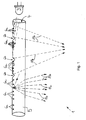
- Fig. 1 it can be seen that adjacent to each other Impurities 6a, 6b each by substantially free of defects Areas are spaced apart and that is the distances formed differently between the defects 6a, 6b and are chosen so that on the interior part to be illuminated 2 along the light guide 5 a predetermined brightness profile results that deviates from uniform lighting.
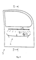
- the interior part 2 is on the inside of a vehicle door 7 arranged and has a door mirror 8, one below the Door mirror 8 arranged armrest 9 and in the armrest integrated functional elements 10 for actuating an electrical Window opener. This is by means of the lighting device 1 Interior part 2 illuminated so that it is for the user of the motor vehicle is visible in the dark, the brightness however, is chosen so that the user and especially the driver of the motor vehicle while driving through the light of the lighting device 1 is not disturbed.
- the functional elements 10 can be easily found in the dark they are illuminated more brightly than the other areas of the Interior fittings part 2.
- the functional elements 10 adjacent section of the light guide 5 have the Impurities 6a, 6b a smaller distance and thus a higher Density on than in the remaining sections of the light guide 5.
- Fig. 1 it can be seen that the normals on the reflective Surfaces of the defects formed as reflector elements 6b relative to the inside of the light guide 5 thereon incident light rays emitted by the illuminant 3 are arranged that the reflected from the impurities 6b, at Extent of the light guide emerging light rays a convergent Form light bundles, the light rays 11b in the direction point to the functional elements 10.
- the light impinging on the defects 6a in each case diffuse light beam with light rays pointing away from each other 11a is scattered.
- This section of the light guide 5 runs about above the area to be illuminated of the door mirror 8 in essentially in the horizontal direction. 4 it can be seen that that the light guide 5 is partially inserted into the door mirror 8 and with its longitudinal central axis approximately parallel to the plane of the Door mirror 8 runs.
- the longitudinal central axis of the Light guide 5 somewhat from the surface plane of the door mirror 8 spaced towards the vehicle interior. In which 4, this distance is chosen to be smaller than the radius of the light guide 5.
- the light guide 5 is arranged behind an aperture 12, the can be integrally formed with the door mirror 8.
- the aperture 12 delimits a channel in which the light guide 5 is arranged.
- the channel has a slit-shaped light exit opening on its underside through which the radiated from the light guide 5 Light passes through.
- Fig. 4 it can be seen that the Light guide 5 emitted light forms a light curtain, the Beams of light reflect the door mirror 8, the armrest 9 and the functional elements 10 illuminate.
- the light guide 5 at least 2 strip-shaped on its outer circumference optical impurity regions 13a, 13b, which are each in Extend the longitudinal direction of the light guide 1.
- At least one of the Impurity areas 13a, 13b have a plurality of impurity areas 6a, 6b, of which in each case adjacent defects 6a, 6b in Extension direction of the light guide 5 at different distances are arranged to each other, so that the Impurity region (s) 13a, 13b illuminated light Set the interior of the motor vehicle in the direction of extension of the light guide 5 an uneven illuminance curve results.
- the impurity regions are in the circumferential direction of the light guide 5 13a, 13b offset from one another without overlap and by in between areas that are essentially free of defects 14a, 14b spaced apart. These trouble-free areas 14a, 14b are also strip-shaped and run on the circumference of the light guide 1 in its longitudinal direction.
- the one in Fig. 5 shown light guide 5 enables the radiation of directed and / or diffuse light in different room sectors the longitudinal central axis of the light guide 5 or in different Beam directions, so that in these spatial sectors or beam directions located interior parts with each desired light distribution can be illuminated. You can if necessary, areas located between these spatial sectors remain unlit, so that that emitted by the lamp 3 Light while avoiding radiation loss in areas that are not to be illuminated, distributed to the areas to be illuminated can be.
- the light guide 5 on his The outer circumference is preferably in the longitudinal direction of the light guide 5 extending circumferential area designed as an optical shoulder 15, the opposite in the circumferential direction on both sides Projecting areas and in the use position in one to the Circumferential area 15 matching receiving recess of a holder is inserted.
- the optics shoulder 15 enables one Rotation about the longitudinal axis of the light guide 1 a correct position Installation of the light guide 1.
- the optical defects 6a, 6b having section of the light guide 5 is over a essentially free of defects, not shown in FIG. 1
- At the back of the door lining are also the electrical power connections for the Illuminant 5 and optionally a control device for the illuminant 5 arranged.
- Lighting device 1 which in particular for lighting the interior or one Interior part 2 of a motor vehicle provided Lighting device 1 thus has at least one lamp 3 and at least one with its light coupling surface 4 in Light emission area of the lamp 3 arranged rod-shaped Light guide 5 on.
- Optical impurities 6a, 6b arranged in the direction of extension of the light guide 5 are offset from one another.
- the impurities 6a, 6b are designed so that the inside of the light guide 5 the light rays striking the defects 6a, 6b are scattered in this way and / or reflected that they emerge from the light guide 5.
- Adjacent defects 6a, 6b are arranged next to each other through essentially interference-free areas spaced. The distances between adjacent to each other Impurities 6a, 6b are different around the interior part 2 to illuminate unevenly.
Landscapes
- Engineering & Computer Science (AREA)
- Mechanical Engineering (AREA)
- Physics & Mathematics (AREA)
- General Physics & Mathematics (AREA)
- Optics & Photonics (AREA)
- Planar Illumination Modules (AREA)
- Arrangements Of Lighting Devices For Vehicle Interiors, Mounting And Supporting Thereof, Circuits Therefore (AREA)
- Vehicle Interior And Exterior Ornaments, Soundproofing, And Insulation (AREA)
Abstract
Description
Die Erfindung betrifft eine Beleuchtungseinrichtung, insbesondere zur Beleuchtung des Innenraumes oder eines Inneneinrichtungsteiles eines Kraftfahrzeugs, mit mindestens einem Leuchtmittel und zumindest einem mit seiner Lichteinkoppelfläche im Lichtabstrahlbereich des Leuchtmittels angeordneten stabförmigen Lichtleiter, der an seinem Außenumfang in Erstreckungsrichtung des Lichtleiters zueinander versetzte optische Störstellen aufweist, an denen innerhalb des Lichtleiters darauf auftreffendes Licht derart gestreut und/oder reflektiert wird, daß es an einem der betreffenden Störstelle gegenüberliegenden Umfangsbereich des Lichtleiters aus diesem austritt, wobei zueinander benachbart nebeneinander angeordneten Störstellen jeweils durch einen im wesentlichen störstellenfreien Bereich voneinander beabstandet sind.The invention relates to a lighting device, in particular for lighting the interior or an interior part a motor vehicle, with at least one lamp and at least one with its light coupling surface in the light emission area the rod-shaped light guide arranged, on its outer circumference in the direction of extension of the light guide has mutually offset optical defects at which scattered light striking it within the light guide and / or is reflected that it is at one of the concerned Impurity point opposite circumferential area of the light guide emerges from this, adjacent to each other side by side arranged impurities each by an essentially interference-free area are spaced apart.
Aus WO 98/33008 kennt man bereits eine Beleuchtungseinrichtung der eingangs genannten Art, bei der die Störstellen durch prismen- oder keilförmige Einformungen gebildet sind, die in die Oberfläche des Lichtleiters eingelassen sind. Dabei sind die prismenförmigen Einformungen mit ihrer Längserstreckungsrichtung jeweils etwa in Umfangsrichtung des im wesentlichen zylindrischen Lichtleiters angeordnet. Die Normalen auf die reflektierenden Oberflächen der Einformungen sind derart relativ zu den innerhalb des Lichtleiters auf die Oberflächen auftreffenden, von dem Leuchtmittel ausgesandten Lichtstrahlen angeordnet, daß das reflektierende Licht auf den dem Reflektorelement gegenüberliegenden Lichtleiter-Umfangsbereich unter einem Winkel auftrifft, der kleiner ist als der Grenzwinkel der Totalreflektion, so daß das Licht dort aus dem Lichtleiter austritt.From WO 98/33008 a lighting device is already known initially mentioned type, in which the imperfections by prismatic or wedge-shaped indentations are formed, which in the surface of the Are inserted. The prismatic ones Deformations with their direction of longitudinal extension approximately in each case Circumferential direction of the substantially cylindrical light guide arranged. The normals on the reflective surfaces the indentations are so relative to those within the Light guide striking the surfaces of the illuminant emitted light rays arranged that the reflecting light on the optical fiber circumferential area opposite the reflector element hits at an angle less than the critical angle of the total reflection, so that the light there from the Light guide emerges.
Um Abschattungen zwischen den Störstellen zu vermeiden, ist zwischen zueinander benachbart nebeneinander angeordneten Störstellen jeweils ein im wesentlichen störstellenfreier Lichtleiter-Oberflächenbereich vorgesehen, in den der Schatten der in Lichtabstrahlrichtung unmittelbar davor befindlichen Störstellen fällt. In Erstreckungsrichtung des Lichtleiters sind die Störstellen in gleichmäßigen Abständen zueinander angeordnet.In order to avoid shadowing between the imperfections, between Impurities arranged next to each other next to each other each have an essentially interference-free light guide surface area provided in which the shadow of the in Light emission direction immediately in front of impurities falls. The defects are in the direction of extension of the light guide arranged at equal distances from each other.
Die Beleuchtungseinrichtung hat den Nachteil, daß für Beleuchtungsaufgaben, bei denen eine zu beleuchtende Zielfläche an wenigstens einer Stelle heller beleuchtet werden soll als an einer dazu benachbarten Stelle, wenigstens eine zusätzliche Beleuchtungseinrichtung benötigt wird, welche die helle(n) Stelle (n) beleuchtet. Derartige ungleichmäßige Helligkeitsverteilungen können beispielsweise bei einer Ambiente-Beleuchtungseinrichtung zum Beleuchten eines Inneneinrichtungsteiles eines Kraftfahrzeugs von Vorteil sein, um an dem Inneneinrichtungsteil befindliche Funktionselemente, wie zum Beispiel einen Schalter zum Betätigen eines Fensterhebers oder ein Betätigungselement zum Verschwenken eines Fahrzeugaußenspiegels, mit größerer Helligkeit zu beleuchten als dazu benachbarte Stellen, die keine Funktionselemente aufweisen.The lighting device has the disadvantage that for lighting tasks, where at least one target surface to be illuminated should be illuminated more brightly in one place than in another neighboring point, at least one additional lighting device is needed, which illuminates the bright spot (s). Such uneven brightness distributions can, for example with an ambient lighting device for lighting an interior part of a motor vehicle may be advantageous, around functional elements located on the interior part, such as a switch to operate a window regulator or an actuating element for pivoting a vehicle exterior mirror, to illuminate with greater brightness than neighboring ones Positions that have no functional elements.
Es besteht deshalb die Aufgabe, eine Beleuchtungseinrichtung der eingangs genannten Art zu schaffen, die auf einfache Weise eine Beleuchtung eines Inneneinrichtungsteiles eines Kraftfahrzeugs mit einer vorgegebenen, ungleichmäßigen Helligkeitsverteilung ermöglicht. There is therefore the task of a lighting device to create the kind mentioned in the simple way a Illumination of an interior part of a motor vehicle with a predetermined, uneven brightness distribution.
Die Lösung dieser Aufgabe besteht darin, daß jeweils zueinander benachbarten Störstellen in Erstreckungsrichtung des Lichtleiters unterschiedliche Abstände zueinander aufweisen.The solution to this problem is that each other neighboring defects in the direction of extension of the light guide have different distances from each other.
In vorteilhafter Weise ist es dadurch möglich, an unterschiedlichen, in Längserstreckungsrichtung des Lichtleiters zueinander versetzten Lichtleiterabschnitten eine unterschiedliche Lichtmenge aus dem Lichtleiter auszukoppeln. Dabei hängt die Menge des in den einzelnen Lichtleiterabschnitten ausgekoppelten Lichts von dem Abstand ab, den in Erstreckungsrichtung des Lichtleiters zueinander benachbart nebeneinander befindliche Störstellen in dem jeweiligen Lichtleiterabschnitt aufweisen. In Lichtleiterabschnitten, in denen zueinander benachbarte Störstellen einen großen Abstand zueinander aufweisen, wird eine geringere Lichtmenge oder ein kleinerer Lichtstrom aus dem Lichtleiter ausgekoppelt als in Lichtleiterabschnitten, in denen zueinander benachbarte Störstellen einen kleinen Abstand zueinander aufweisen. Durch Wahl eines entsprechenden Abstandes zwischen den Störstellen der einzelnen Lichtleiterabschnitte ist es bei der Konstruktion oder Herstellung der Beleuchtungseinrichung auf einfache Weise möglich, die pro Längeneinheit von dem Lichtleiter abgestrahlte Lichtmenge an einen auf dem zu beleuchtenden Inneneinrichtungsteils eines Kraftfahrzeugs gewünschten ungleichmäßigen Helligkeitsverlauf anzupassen.This advantageously makes it possible to use different to each other in the longitudinal direction of extension of the light guide offset light guide sections a different amount of light to couple out of the light guide. The amount depends on the individual light guide sections decoupled light from the Distance from that in the direction of extension of the light guide Impurities located adjacent to one another in the have respective light guide section. In light guide sections, in which neighboring impurities a large distance have a smaller amount of light or a smaller luminous flux is coupled out of the light guide than in Optical fiber sections in which mutually adjacent impurities have a small distance from each other. By choosing one corresponding distance between the defects of the individual It is fiber optic sections in the design or manufacture the lighting device possible in a simple way, the pro Unit of length of light emitted by the light guide to one on the interior part of a motor vehicle to be illuminated adjust the desired uneven brightness curve.
Vorteilhaft ist, wenn die Störstellen unterschiedliche Abmessungen aufweisen. Durch diese Maßnahme kann der Helligkeitsverlauf entlang einer parallel zur Längserstreckungsrichtung des Lichtleiters auf der zu beleuchtenden Zielfläche verlaufenden Linie bei der Konstruktion oder Herstellung der Beleuchtungseinrichtung noch besser an ein vorgegebenes Helligkeitsprofil angepaßt werden.It is advantageous if the defects have different dimensions exhibit. This measure allows the brightness curve along a parallel to the longitudinal direction of the light guide on the target surface to be illuminated at the line Design or manufacture of the lighting device even better can be adapted to a given brightness profile.
Bei einer zweckmäßigen Ausgestaltung der Erfindung weisen die Störstellen einen unterschiedlichen Lichtreflexions- und/oder Lichtstreugrad auf. Dadurch kann eine noch ungleichmäßigere Beleuchtung unterschiedlicher Bereiche des zu beleuchtenden Innenraumes oder Inneneinrichtungsteiles des Kraftfahrzeugs erreicht werden.In an expedient embodiment of the invention, the Impurities a different light reflection and / or Light scattering wheel on. This can make an even more uneven Illumination of different areas of the area to be illuminated Interior or interior part of the motor vehicle reached become.
Bei einer vorteilhaften Ausgestaltung der Erfindung ist vorgesehen, daß das die Störstellen unterschiedliche Arten von optischen Defekten aufweisen und daß insbesondere wenigstens eine Störstelle durch mindestens ein Reflektorelement und wenigstens eine weitere Störstelle durch zumindest ein optisches Streuelement gebildet sind. Auch durch diese Maßnahme kann der Helligkeitsverlauf entlang einer in der zu beleuchtenden Zielfläche parallel zur Längserstreckungsrichtung des Lichtleiters verlaufenden Linie bei der Herstellung der Beleuchtungseinrichtung an ein vorgegebenes Helligkeitsprofil angepasst werden.In an advantageous embodiment of the invention, that the impurities are different types of optical Have defects and that in particular at least one defect by at least one reflector element and at least one further Interference point are formed by at least one optical scattering element. This measure can also be used to adjust the brightness curve along a in the target area to be illuminated parallel to the longitudinal direction of the light guide line at the Manufacture of the lighting device to a predetermined Brightness profile can be adjusted.
Vorteilhaft ist, wenn mehrere, in Erstreckungsrichtung des Lichtleiters zueinander versetzte Störstellen als Reflektorelemente ausgebildetet sind, und wenn die Normalen auf die reflektierenden Oberflächen dieser Reflektorelemente derart relativ zu den darauf auftreffenden, von dem Leuchtmittel ausgesandten Lichtstrahlen angeordnet sind, daß die von den Reflektorelementen reflektierten, am Umfang des Lichtleiters auftretenden Lichtstrahlen ein konvergentes Lichtbündel bilden. Dadurch ist es insbesondere möglich, im Innenraum eines Kraftfahrzeugs angeordnete Funktionselemente, wie zum Beispiel einen Türöffner zum Öffnen einer Fahrzeugtüre, einen am Dachhimmel angebrachten Haltegriff, einen Schalter zum Bestätigen eines elektrischen Fensterhebers oder Schiebedachs mit im Vergleich zur Helligkeit dazu benachbarter beleuchteter Bereiche mit noch größerer Helligkeit zu beleuchten.It is advantageous if several, in the direction of extension of the Interfaces offset from each other as light guide as reflector elements are trained, and if the normals on the reflective Surfaces of these reflector elements are relative to those on them incident light rays emitted by the illuminant are arranged so that the reflected by the reflector elements light rays appearing on the circumference of the light guide form convergent light beam. This makes it possible in particular functional elements arranged in the interior of a motor vehicle, such as a door opener for opening a vehicle door, a handle attached to the headliner, a switch for Confirm an electric window lifter or sunroof with compared to the brightness of adjacent illuminated areas to illuminate with even greater brightness.
Bei einer vorteilhaften Ausführungsform der Erfindung ist vorgesehen, daß wenigstens eine optische Störstelle als Streuelement eine Farbschicht aufweist und daß gegebenenfalls mindestens eine weitere Störstelle farblos ausgebildet ist oder eine Farbschicht aufweist, deren Farbe sich von der Farbe der zuerst genannten Farbschicht unterscheidet. Dadurch ist es möglich, unterschiedliche Stellen der Inneneinrichtung eines Kraftfahrzeugs mit unterschiedlich farbigem Licht zu beleuchten. So kann beispielsweise ein im Innenraum des Kraftfahrzeugs befindliches Funktions- oder Bedienelement mit weißem Licht und von dem Funktions- oder Bedienelement beabstandete Bereiche mit farbigem, beispielsweise mit gelben oder rotem Licht beleuchtet werden.In an advantageous embodiment of the invention provided that at least one optical defect as a scattering element has a layer of paint and that optionally at least one another defect is colorless or a layer of paint whose color differs from the color of the first Color layer differs. This makes it possible to have different Set the interior of a motor vehicle with to illuminate different colored light. For example a functional or located in the interior of the motor vehicle Control element with white light and from the functional or Control element spaced areas with colored, for example be illuminated with yellow or red light.
Bei einer zweckmäßigen Ausgestaltung der Erfindung weist der Lichtleiter einen von einer geraden Linie abweichenden, an die Form eines Inneneinrichtungsteiles eines Kraftfahrzeugs angepaßten gekrümmten Verlauf auf. Der Lichtleiter kann dann unmittelbar an dem Inneneinrichtungsteil angeordnet und gegebenenfalls zumindest mit einem Teilbereich seines Querschnitts in dessen Oberfläche eingelassen sein.In an expedient embodiment of the invention, the Light guide a shape that deviates from a straight line an interior part of a motor vehicle adapted curved course. The light guide can then turn on immediately arranged the interior part and optionally at least with a portion of its cross-section in its surface be let in.
Besonders vorteilhaft ist, wenn der Lichtleiter an seinem Außenumfang einen sich vorzugsweise in Längsrichtung des Lichtleiters erstreckenden Umfangsbereich hat, der gegenüber einem in Umfangsrichtung dazu benachbarten Bereich vorsteht oder zurückspringt. Dieser Umfangsbereich kann dann als Optikschulter zum lagerichtigen Positionieren des Lichtleiters bei der Montage dienen. Die Optikschulter kann beispielsweise in eine dazu passende Nut einer Halterung oder eines Inneneinrichtungsteils, an dem der Lichtleiter befestigt werden soll, eingesetzt werden.It is particularly advantageous if the light guide on its outer circumference one preferably in the longitudinal direction of the light guide extending circumferential region, which is opposite to one in the circumferential direction projecting or jumping back to the adjacent area. This circumferential area can then be used as an optical shoulder for correct positioning Position the light guide during assembly. The optics shoulder can, for example, fit into a suitable groove a bracket or an interior part on which the Light guide should be attached, are used.
Bei einer vorteilhaften Ausführungsform der Erfindung ist vorgesehen, daß der Lichtleiter an seinem Außenumfang wenigstens zwei in Umfangsrichtung des Lichtleiters versetzt zueinander angeordnete optische Störstellenbereiche aufweist, die jeweils innerhalb eines sich am Außenumfang des Lichtleiters in dessen Längsrichtung erstreckenden streifenförmigen Bereiches angeordnet sind, und daß wenigstens zwei dieser streifenförmigen Bereiche in Umfangsrichtung überlappungsfrei durch dazwischen befindliche störstellenfreie streifenförmige Bereiche voneinander beabstandet sind. Dadurch ergibt sich ein einfach aufgebauter Lichtleiter, der es ermöglicht, mehrere zu beleuchtenden Stellen, bei denen die geraden Verbindungslinien zwischen dem Lichtleiter und den zu beleuchtenden Stellen in unterschiedlichen Richtungen angeordnet sind, mittels nur eines einzigen Lichtleiters mit getrennten Lichtbündeln zu beleuchten. Die Beleuchtungseinrichtung ermöglicht die Abstrahlung von gerichtetem und/oder diffusem Licht in unterschiedlicher Raumsektoren bezüglich der Längsmittelachse des Lichtleiters oder in unterschiedlicher Abstrahlrichtungen, so daß in diesen Raumsektoren oder Abstrahlrichtungen befindliche Inneneinrichtungsteile mit der jeweils gewünschten Lichtverteilung beleuchtet werden können. Dabei können gegebenenfalls zwischen diesen Raumsektoren befindliche Bereiche unbeleuchtet bleiben, so daß das von dem Leuchtmittel abgestrahlte Licht unter Vermeidung von Abstrahlverlusten in Bereiche, die nicht beleuchtet werden sollen, auf die zu beleuchtenden Stellen verteilt werden kann. Gegebenenfalls ist es sogar möglich. die Störstellenbereiche so auszubilden, daß die in den unterschiedlichen Raumsektoren befindlichen, zu beleuchtenden Stellen mit einer unterschiedlichen Helligkeit beleuchtet werden. Die in Längserstreckungsrichtung des Lichtleiters orientierten Abstände von jeweils zueinander benachbart nebeneinander befindlichen Störstellen können in wenigstens einem Störstellenbereich unterschiedlich und in wenigstens einem weiteren Störstellenbereich bei allen dort befindlichen Störstellen gleich groß sein. Es sind aber auch andere Ausführungsformen denkbar, bei denen die Abstände von jeweils zueinander benachbart nebeneinander befindlichen Störstellen in allen Störstellenbereichen unterschiedlich sind.In an advantageous embodiment of the invention, that the light guide on its outer circumference at least two in Circumferential direction of the light guide offset from one another has optical impurity areas, each within a on the outer circumference of the light guide in its longitudinal direction extending strip-shaped area are arranged, and that at least two of these strip-shaped areas in the circumferential direction free of overlaps due to the free of interferences strip-shaped areas are spaced apart. This gives a simply constructed light guide that enables several places to be illuminated, where the straight connecting lines between the light guide and the areas to be illuminated are arranged in different directions by means of only one to illuminate single light guide with separate light beams. The lighting device enables the emission of directional and / or diffuse light in different room sectors with respect to the longitudinal center axis of the light guide or in different Beam directions, so that in these spatial sectors or Radiation directions located interior parts with each desired light distribution can be illuminated. there may be located between these sectors of space Areas remain unlit, so that the illuminant emitted light while avoiding radiation losses in Areas that should not be illuminated on the areas to be illuminated Jobs can be distributed. It may even be possible. form the impurity areas so that the in the different areas of the room to be illuminated are illuminated with a different brightness. In the Distances oriented in the longitudinal direction of the light guide of adjacent to each other Impurities can be in at least one impurity area different and in at least one further defect area be the same size for all defects located there. There are but other embodiments are also conceivable in which the distances of adjacent to each other Impurities are different in all impurity areas.
Bei einer bevorzugten Ausführungsform der Erfindung ist der Lichtleiter und/oder das Leuchtmittel hinter einer Blende angeordnet, wobei diese Blende vorzugsweise durch einen Teilbereich des Inneneinrichtungsteiles gebildet ist. Der Lichtleiter und das Leuchtmittel sind dann für den Benutzer des Kraftfahrzeugs unsichtbar hinter der Blende angeordnet, wodurch es möglich ist, die Beleuchtungseinrichtung unauffällig in die Inneneinrichtung des Kraftfahrzeugs zu integrieren. Außerdem wird durch die Blende eventuell aus dem Lichtleiter austretendes Streulicht, daß vom Benutzer der Beleuchtungseinrichtung als störend empfunden wird, abgedeckt.In a preferred embodiment of the invention, the Light guide and / or the illuminant arranged behind a panel, this aperture preferably through a portion of the Interior part is formed. The light guide and that Illuminants are then invisible to the user of the motor vehicle arranged behind the bezel, making it possible to Lighting device inconspicuous in the interior of the Integrate motor vehicle. Also, through the bezel any scattered light emerging from the light guide that from User of the lighting device is perceived as disturbing, covered.
Bei einer besonders vorteilhaften Ausführungsform der Erfindung ist zumindest ein Abschnitt des Lichtleiters zur Beleuchtung des Türspiegels einer Fahrzeugtüre an der Türinnenverkleidung der Fahrzeugtüre angeordnet, wobei der Lichtleiter vorzugsweise etwa parallel zur Ebene des Türspiegels verläuft. Der Lichtleiter kann dann beispielsweise am oberen Rand des Türspiegels hinter einer dort befindlichen Blende angeordnet sein.In a particularly advantageous embodiment of the invention is at least a section of the light guide for illuminating the Door mirror of a vehicle door on the door lining of the Vehicle door arranged, the light guide preferably about runs parallel to the level of the door mirror. The light guide can then for example at the top of the door mirror behind one aperture located there may be arranged.
Vorteilhaft ist, wenn die optischen Störstellen von der Lichteinkoppelfläche des Lichtleiters durch einen im wesentlichen störstellenfreien Lichtleiterabschnitt beabstandet sind. Die Lichteinkoppelfläche und das Leuchtmittel können dann an einer von den Lichtauskoppelflächen des Lichtleiters beabstandeten Stelle angeordnet sein, beispielsweise im Inneren eines Inneneinrichtungsteiles des Kraftfahrzeugs oder hinter einer Verkleidung.It is advantageous if the optical defects from the light coupling surface of the light guide through one essentially Interference-free light guide section are spaced. The Light coupling surface and the illuminant can then on one of the light decoupling surfaces of the light guide spaced point be arranged, for example in the interior of an interior part of the motor vehicle or behind a panel.
Nachfolgend ist ein Ausführungsbeispiel der Erfindung anhand der Zeichnung näher erläutert. Es zeigen zum Teil stärker schematisiert:
- Fig. 1
- eine ein Leuchtmittel und einen Lichtleiter ausweisende Beleuchtungseinrichtung zur Beleuchtung eines Inneneinrichtungsteiles eines Kraftfahrzeug, wobei auch einige Lichtstrahlen strichliniert dargestellt sind,
- Fig. 2
- eine Ansicht auf die Innenseite einer Fahrzeugtüre, die eine Beleuchtungseinrichtung zum Beleuchten ihres Türspiegels aufweist, wobei beispielhaft auch einige Lichtstrahlen strichliniert dargestellt sind,
- Fig. 3
- einen Querschnitt durch die Fahrzeugtüre in der in Fig. 2 mit III bezeichneten Ebene,
- Fig. 4
- einen vergrößerten Ausschnitt aus Fig. 3, der den in den Türspiegel eingelassenen Lichtleiter besonders gut erkennen läßt, und
- Fig. 5
- einen Querschnitt durch einen Lichtleiter, der zwei in Umfangsrichtung versetzt zueinander angeordnete optische Störstellenbereiche aufweist.
- Fig. 1
- an illuminating device having an illuminant and a light guide for illuminating an interior part of a motor vehicle, some light beams also being shown in dashed lines,
- Fig. 2
- 3 shows a view of the inside of a vehicle door which has an illumination device for illuminating its door mirror, some light beams also being shown in dashed lines by way of example,
- Fig. 3
- 3 shows a cross section through the vehicle door in the plane designated III in FIG. 2,
- Fig. 4
- 3, which shows the light guide embedded in the door mirror particularly well, and
- Fig. 5
- a cross section through an optical fiber which has two optical impurity regions arranged offset to one another in the circumferential direction.
Eine im ganzen mit 1 bezeichnete Beleuchtungseinrichtung zur
Beleuchtung eines Inneneinrichtungsteiles 2 eines Kraftfahrzeugs
weist als Leuchtmittel 3 eine Leuchtdiode auf, die mit ihrer
Abstrahlseite der Lichteinkoppelfläche 4 eines Lichtleiters 5
zugewandt ist. In Fig. 1 ist erkennbar, daß der Lichtleiter 5 im
wesentlichen stabförmig ausgebildet ist und einen etwa zylindrischen
Querschnitt aufweist. Das Leuchtmittel 3 ist an einer der
Stirnseiten des Lichtleiters 5 angeordnet. Es sind aber auch andere
Ausführungsbeispiele denkbar, bei denen die Lichteinkoppelfläche
4 an einem Teilbereich des Außenumfangs des Lichtleiters 5 vorgesehen
sein kann und/oder bei denen das von dem Leuchtmittel 3 entfernte
Stirnende des Lichtleiters 5 verspiegelt ist. Es können auch an
beiden Enden des Lichtleiters 5 Leuchtmittel 3 angeordnet sein.A lighting device designated as a whole with 1 for
Illumination of an
In Fig. 1 ist erkennbar, daß der Lichtleiter 5 an seinem Außenumfang
mehrere in Erstreckungsrichtung des Lichtleiters 5 zueinander
versetzte optische Störstellen 6a, 6b, aufweist, von denen die
Störstellen 6a durch eine lichtstreuende Lackschicht und die
Störstellen 6b als in die Oberfläche des Lichtleiters 5 eingelassene
Prismen ausgebildet sind. Anstelle der Farbschicht oder zusätzlich
zu dieser können die Störstellen 6a auch lichtstreuende Oberflächendefekte
aufweisen, beispielsweise eine rauhe Oberflächenstruktur.In Fig. 1 it can be seen that the
Das innerhalb des Lichtleiters 5 auf die Störstellen 6a auftreffende,
von dem Leuchtmittel 3 abgestrahlte Licht wird an den Störstellen
6a, 6b so gestreut, daß es an einem den betreffenden Störstellen
6a gegenüberliegenden Umfangsbereich des Lichtleiters 5
unter einem Winkel auf die Oberfläche des Lichtleiters 5 auftrifft,
bei dem die Bedingung für Totalreflektion nicht mehr erfüllt ist.
Das innerhalb des Lichtleiters 5 auf die Störstellen 6b auftreffende
Licht wird an diesen unter Ausnutzung der Totalreflektion
reflektiert und trifft an der den betreffenden Störstellen 6b
gegenüberliegenden Umfangsbereich des Lichtleiters 5 unter einem
Winkel auf die Oberfläche des Lichtleiters 5 auf, bei dem die
Bedingung für Totalreflektion nicht mehr erfüllt ist. Somit tritt
das auf die Störstellen 6a, 6b auftreffende Licht an der den
Störstellen 6a, 6b gegenüberliegenden Seite des Lichtleiters aus
diesem aus.The
In Fig. 1 ist erkennbar, daß benachbart zueinander angeordnete
Störstellen 6a, 6b jeweils durch im wesentlichen störstellenfreie
Bereiche voneinander beabstandet sind und das die Abstände
zwischen den Störstellen 6a, 6b unterschiedlich ausgebildet und
so gewählt sind, daß sich auf dem zu beleuchtenden Inneneinrichtunsteil
2 entlang des Lichtleiters 5 ein vorgegebenes Helligkeitsprofil
ergibt, das von einer gleichmäßigen Beleuchtung abweicht.In Fig. 1 it can be seen that adjacent to each
Das Inneneinrichtungsteil 2 ist an der Innenseite einer Fahrzeugtüre
7 angeordnet und weist einen Türspiegel 8, eine unterhalb des
Türspiegels 8 angeordnete Armauflage 9 und in der Armauflage
integrierte Funktionselemente 10 zum Betätigen eines elektrischen
Fensterhebers auf. Mittels der Beleuchtungseinrichtung 1 ist das
Inneneinrichtungsteil 2 so beleuchtbar, daß es für den Benutzer
des Kraftfahrzeugs im Dunkeln zwar sichtbar ist, wobei die Helligkeit
jedoch so gewählt ist, daß der Benutzer und insbesondere der Fahrer
des Kraftfahrzeugs während der Fahrt durch das Licht der Beleuchtungseinrichtung
1 nicht gestört wird.The
Damit die Funktionselemente 10 bei Dunkelheit leicht auffindbar
sind, sind sie heller beleuchtet als die übrigen Bereiche des
Inneneinrichtungsteiles 2. In einem zu den Funktionselementen 10
benachbarten Abschnitt des Lichtleiters 5 weisen dazu die
Störstellen 6a, 6b einen geringeren Abstand und somit eine höhere
Dichte auf als in den übrigen Abschnitten des Lichtleiters 5.So that the
In Fig. 1 ist erkennbar, daß die Normalen auf die reflektierenden
Oberflächen der als Reflektorelemente ausgebildeten Störstellen
6b derart relativ zu den innerhalb des Lichtleiters 5 darauf
auftreffenden, von dem Leuchtmittel 3 ausgesandten Lichtstrahlen
angeordnet sind, daß die von den Störstellen 6b reflektierten, am
Umfang des Lichtleiters austretenden Lichtstrahlen ein konvergentes
Lichtbündel bilden, dessen Lichstrahlen 11b in Richtung
auf die Funktionselemente 10 weisen. In Fig. 1 ist weiter erkennbar,
daß auf die Störstellen 6a auftreffendes Licht jeweils in ein
diffuses Lichtbündel mit voneinander wegweisenden Lichtstrahlen
11a gestreut wird.In Fig. 1 it can be seen that the normals on the reflective
Surfaces of the defects formed as
Wie in Fig. 1 besonders gut erkennbar ist, ist der die Störstellen
6a, 6b aufweisende Abschnitt des Lichtleiters 5 an der Türinnenverkleidung
der Fahrzeugtüre etwa in der Ebene des Türspiegels 8
angeordnet. Dabei verläuft dieser Abschnitt des Lichtleiters 5
etwa oberhalb des zu beleuchtenden Bereichs des Türspiegels 8 im
wesentlichen in horizontaler Richtung. In Fig. 4 ist erkennbar,
daß der Lichtleiter 5 bereichsweise in den Türspiegel 8 eingelassen
und mit seiner Längsmittelachse etwa parallel zur Ebene des
Türspiegels 8 verläuft. Dabei ist die Längsmittelachse des
Lichtleiters 5 etwas von der Oberflächenebene des Türspiegels 8
in Richtung zum Fahrzeuginnenraum hin beabstandet. Bei dem
Ausführungsbeispiel nach Fig. 4 ist dieser Abstand kleiner gewählt
als der Radius des Lichtleiters 5.As can be seen particularly well in FIG. 1, this is the
Der Lichtleiter 5 ist hinter einer Blende 12 angeordnet, die
einstückig mit dem Türspiegel 8 ausgebildet sein kann. Die Blende
12 begrenzt einen Kanal, in dem der Lichtleiter 5 angeordnet ist.
An seiner Unterseite weist der Kanal eine schlitzförmige Lichtaustrittsöffnung
auf, durch die das von dem Lichtleiter 5 abgestrahlte
Licht hindurchtritt. In Fig. 4 ist erkennbar, daß das von dem
Lichtleiter 5 abgestrahlte Licht einen Lichtvorhang bildet, dessen
Lichtstrahlen den Türspiegel 8, die Armauflage 9 und die Funktionselemente
10 beleuchten.The
Bei dem Ausführungsbeispiel nach Fig. 5 weist der Lichtleiter 5
an seinem Außenumfang wenigstens 2 streifenförmig ausgebildete
optische Störstellenbereiche 13a, 13b auf, die sich jeweils in
Längsrichtung des Lichtleiters 1 erstrecken. Zumindest einer der
Störstellenbereiche 13a, 13b weist mehrere Störstellen 6a, 6b auf,
von denen jeweils zueinander benachbarte Störstellen 6a, 6b in
Erstreckungsrichtung des Lichtleiters 5 in unterschiedlichen Abstände
zueinander angeordnet sind, so daß sich an den von dem auf diese(n)
Störstellenbereich(e) 13a, 13b auftreffenden Licht beleuchteten
Stellen der Inneneinrichtung des Kraftfahrzeugs in Erstreckungsrichtung
des Lichtleiters 5 eine ungleichmäßiger Beleuchtungsstärkeverlauf
ergibt.5, the
In Umfangsrichtung des Lichtleiters 5 sind die Störstellenbereiche
13a, 13b überlappungsfrei zueinander versetzt und durch dazwischen
befindliche, im wesentlichen störstellenfreie Bereiche
14a, 14b voneinander beabstandet. Diese störstellenfreien Bereiche
14a, 14b sind ebenfalls streifenförmig ausgebildet und verlaufen
am Umfang des Lichtleiters 1 in dessen Längsrichtung. Der in Fig. 5
gezeigte Lichtleiter 5 ermöglicht die Abstrahlung von gerichtetem
und/oder diffusem Licht in unterschiedliche Raumsektoren bezüglich
der Längsmittelachse des Lichtleiters 5 oder in unterschiedliche
Abstrahlrichtungen, so daß in diesen Raumsektoren oder Abstrahlrichtungen
befindliche Inneneinrichtungsteile mit der jeweils
gewünschten Lichtverteilung beleuchtet werden können. Dabei können
gegebenenfalls zwischen diesen Raumsektoren befindliche Bereiche
unbeleuchtet bleiben, so daß das von dem Leuchtmittel 3 abgestrahlte
Licht unter Vermeidung von Abstrahlverlusten in Bereiche, die nicht
beleuchtet werden sollen, auf die zu beleuchteten Stellen verteilt
werden kann. The impurity regions are in the circumferential direction of the
In Fig. 5 ist noch erkennbar, daß der Lichtleiter 5 an seinem
Außenumfang einen sich vorzugsweise in Längsrichtung des Lichtleiters
5 erstreckenden, als Optikschulter ausgebildeten Umfangsbereich
15 hat, der gegenüber in Umfangsrichtung beidseits dazu benachbarten
Bereichen vorsteht und in Gebrauchsstellung in eine zu dem
Umfangsbereich 15 passende Aufnahmevertiefung einer Halterung
eingesetzt ist. Die Optikschulter 15 ermöglicht bezüglich einer
Drehung um die Längsachse des Lichtleiters 1 einen lagerichtigen
Einbau des Lichtleiters 1.In Fig. 5 it can still be seen that the
Der hinter der Blende 12 angeordnete, die optischen Störstellen
6a, 6b aufweisende Absschnitt des Lichtleiters 5 ist über einen
im wesentlichen störstellenfreien, in Fig. 1 nicht näher dargestellten
Lichtleiterabschnitt mit dem an der dem Fahrzeuginnenraum
abgewandten Rückseite der Türinnenverkleidung angeordneten
Leuchtmittel 3 verbunden. An der Rückseite der Türinnenverkleidung
sind außerdem die elektrische Stromversorgungsanschlüsse für das
Leuchtmittel 5 sowie gegebenenfalls eine Ansteuereinrichtung für
das Leuchtmittel 5 angeordnet.The one behind the
Die insbesondere zur Beleuchtung des Innenraums oder eines
Inneneinrichtungsteils 2 eines Kraftfahrzeugs vorgesehene
Beleuchtungseinrichtung 1 weist also mindestens ein Leuchtmittel
3 und zumindest einen mit seiner Lichteinkoppelfläche 4 im
Lichtabstrahlbereich des Leuchtmittels 3 angeordneten stabförmigen
Lichtleiter 5 auf. Am Außenumfang des Lichtleiters 5 sind
optische Störstellen 6a, 6b angeordnet, die in Erstreckungsrichtung
des Lichtleiters 5 zueinander versetzt sind. Die Störstellen 6a,
6b sind so ausgebildet, daß die innerhalb des Lichtleiters 5 auf
die Störstellen 6a, 6b auftreffende Lichtstrahlen derart gestreut
und/oder reflektiert werden, daß sie aus dem Lichtleiter 5 austreten.
Benachbart nebeneinander angeordneten Störstellen 6a, 6b sind jeweils
durch im wesentlichen störstellenfreie Bereiche voneinander
beabstandet. Die Abstände zwischen jeweils zueinander benachbarten
Störstellen 6a, 6b sind unterschiedlich, um das Inneneinrichtungsteil
2 ungleichmäßig zu beleuchten.Which in particular for lighting the interior or one
Claims (12)
Applications Claiming Priority (2)
| Application Number | Priority Date | Filing Date | Title |
|---|---|---|---|
| DE20019073U DE20019073U1 (en) | 2000-11-09 | 2000-11-09 | Lighting device |
| DE20019073U | 2000-11-09 |
Publications (2)
| Publication Number | Publication Date |
|---|---|
| EP1205352A2 true EP1205352A2 (en) | 2002-05-15 |
| EP1205352A3 EP1205352A3 (en) | 2009-11-04 |
Family
ID=7948630
Family Applications (1)
| Application Number | Title | Priority Date | Filing Date |
|---|---|---|---|
| EP20010125957 Withdrawn EP1205352A3 (en) | 2000-11-09 | 2001-10-31 | Lighting device |
Country Status (2)
| Country | Link |
|---|---|
| EP (1) | EP1205352A3 (en) |
| DE (1) | DE20019073U1 (en) |
Cited By (12)
| Publication number | Priority date | Publication date | Assignee | Title |
|---|---|---|---|---|
| DE102004054732A1 (en) * | 2004-11-14 | 2006-05-24 | Fer Fahrzeugelektrik Gmbh | Optical fiber arrangement for external rear view mirror of vehicle, has stretched optical fiber rod that is approximately parallel to edge of plate shaped optical fiber, and light source connected to front end of optical fiber rod |
| WO2007003663A1 (en) * | 2005-07-05 | 2007-01-11 | Grupo Antolin-Ingenieria, S.A. | Interior lining element for a motor vehicle, motor vehicle and method of producing said lining element |
| DE102007046197A1 (en) | 2007-09-26 | 2009-04-02 | Hella Kgaa Hueck & Co. | Signal lamp for vehicles, particularly license plate light, has rod-shaped light conductor, where light uncoupling surface is formed in segmented manner with two surface sections of different contours |
| ES2332641A1 (en) * | 2005-07-05 | 2010-02-09 | Grupo Antolin-Ingenieria, S.A. | Interior lining element for a motor vehicle, motor vehicle and method of producing said lining element |
| DE102007023076B4 (en) * | 2007-05-16 | 2012-02-16 | Automotive Lighting Reutlingen Gmbh | Lighting device for motor vehicles |
| WO2016077110A1 (en) * | 2014-11-12 | 2016-05-19 | 3M Innovative Properties Company | Illumination system including lightguide |
| WO2017031517A1 (en) * | 2015-08-27 | 2017-03-02 | Zkw Group Gmbh | Light module for vehicle headlight |
| DE102016103568A1 (en) | 2016-02-29 | 2017-08-31 | Automotive Lighting Reutlingen Gmbh | Automotive lighting device with an elongated light guide |
| WO2017151299A1 (en) * | 2016-03-01 | 2017-09-08 | 3M Innovative Properties Company | Optical structures with off-state appearance area |
| CN107430239A (en) * | 2014-11-12 | 2017-12-01 | 3M创新有限公司 | Illuminator including light guide |
| CN114945775A (en) * | 2020-04-02 | 2022-08-26 | 宝马股份公司 | Lighting device for a motor vehicle |
| DE102014103737B4 (en) * | 2014-03-19 | 2025-10-23 | HELLA GmbH & Co. KGaA | Lighting device for vehicles |
Families Citing this family (21)
| Publication number | Priority date | Publication date | Assignee | Title |
|---|---|---|---|---|
| DE10347053A1 (en) | 2003-10-07 | 2005-05-04 | Hella Kgaa Hueck & Co | Interior light for vehicles |
| DE10123263B4 (en) * | 2001-05-12 | 2005-12-08 | Daimlerchrysler Ag | Light guide system for the interior of a motor vehicle |
| DE10231325A1 (en) * | 2002-07-11 | 2004-02-12 | Hella Kg Hueck & Co. | Lighting device for vehicles |
| DE10314352A1 (en) * | 2003-03-31 | 2004-10-14 | Hella Kg Hueck & Co. | Illumination device for vehicle interior has light guide part of light conducting element with input coupling surfaces and holders at both ends for mirrors that leave input coupling surfaces exposed |
| DE10328216A1 (en) | 2003-06-24 | 2005-01-13 | Hella Kgaa Hueck & Co. | Lighting device for a vehicle |
| DE102004044341B4 (en) * | 2003-10-13 | 2017-09-07 | Heidelberger Druckmaschinen Ag | Sheet-fed printing machine with optical sensor arrangement for a printing material |
| DE10351048A1 (en) * | 2003-10-31 | 2005-05-25 | Bayerische Motoren Werke Ag | Vehicle headlamp has reflector edge opposite first end surface advanced in radiation direction, forming second reflector region that deflects light to first end surface and couples it into output coupling element |
| DE102004044035B4 (en) * | 2004-09-09 | 2007-05-31 | MöllerTech GmbH | Plastic component, in particular trim part for the vehicle interior |
| DE102005011715B4 (en) * | 2005-03-11 | 2008-09-25 | Hella Kgaa Hueck & Co. | Interior light of a vehicle |
| DE102006015156A1 (en) * | 2006-03-30 | 2007-10-04 | Hella Kgaa Hueck & Co. | Lightening device e.g. for interior space of motor vehicle, has bulb and lighting coupling surface in light emitting range of light bulb and having arranged fiber optic cable |
| EP1898147B1 (en) * | 2006-09-11 | 2017-06-07 | Hella KGaA Hueck & Co. | Lighting device for vehicle |
| DE102007058272A1 (en) | 2007-12-04 | 2009-06-18 | Audi Ag | Lining element for use in interior of motor vehicle, has light source i.e. LED, connected with inner layer to inject light into inner layer, and decorative element with partial translucence arranged between outer and inner layers |
| DE102008049040A1 (en) * | 2008-02-29 | 2009-09-10 | Preh Gmbh | Device for the backlighting of an interior judgment for a motor vehicle |
| US8333493B2 (en) | 2009-04-03 | 2012-12-18 | North American Lighting, Inc. | Dual-direction light pipe for automotive lighting |
| DE102010003270A1 (en) * | 2010-03-25 | 2011-09-29 | Bayerische Motoren Werke Aktiengesellschaft | Interior lighting system for motor vehicle, has light guide and light source, which is designed and arranged such that light of light source is coupled into light guide at one end of light guide |
| JP5582981B2 (en) * | 2010-11-18 | 2014-09-03 | 株式会社小糸製作所 | Light guide member |
| DE102011014919A1 (en) * | 2011-03-24 | 2012-09-27 | Volkswagen Ag | Vehicle lamp, in particular for illuminating the interior of the vehicle |
| DK177763B1 (en) * | 2012-11-26 | 2014-06-16 | Bang & Olufsen As | A compact lens arrangement |
| US11256018B2 (en) | 2019-07-03 | 2022-02-22 | Varroc Lighting Systems, s.r.o | Light assembly including an illuminating utility segment and a visual stimulant segment |
| DE102019213357A1 (en) * | 2019-09-03 | 2021-03-04 | HELLA GmbH & Co. KGaA | Overhead console |
| DE102020116264B4 (en) | 2020-04-08 | 2026-02-26 | OSRAM CONTINENTAL GmbH | VEHICLE COMPONENT AND VEHICLE |
Citations (1)
| Publication number | Priority date | Publication date | Assignee | Title |
|---|---|---|---|---|
| WO1998033008A1 (en) | 1997-01-28 | 1998-07-30 | Minnesota Mining And Manufacturing Company | Optical fiber illumination system |
Family Cites Families (5)
| Publication number | Priority date | Publication date | Assignee | Title |
|---|---|---|---|---|
| DE8712678U1 (en) | 1987-09-19 | 1989-01-19 | Preh, Elektrofeinmechanische Werke Jakob Preh Nachf. Gmbh & Co, 8740 Bad Neustadt | Device for operating an electrical device |
| DE4329914A1 (en) | 1993-09-04 | 1995-03-09 | Willing Gmbh Dr Ing | Linear optical waveguide (light guide) |
| DE29721892U1 (en) * | 1997-01-23 | 1998-03-12 | Diemer & Fastenrath, 58511 Lüdenscheid | Optical fiber with radial light coupling |
| DE19702174B4 (en) | 1997-01-23 | 2004-04-01 | Diemer & Fastenrath Gmbh & Co.Kg | Circular cylindrical optical fiber with radial light coupling |
| JP4394839B2 (en) | 1999-02-24 | 2010-01-06 | スリーエム イノベイティブ プロパティズ カンパニー | Lighting device that produces a predetermined intensity pattern |
-
2000
- 2000-11-09 DE DE20019073U patent/DE20019073U1/en not_active Expired - Lifetime
-
2001
- 2001-10-31 EP EP20010125957 patent/EP1205352A3/en not_active Withdrawn
Patent Citations (1)
| Publication number | Priority date | Publication date | Assignee | Title |
|---|---|---|---|---|
| WO1998033008A1 (en) | 1997-01-28 | 1998-07-30 | Minnesota Mining And Manufacturing Company | Optical fiber illumination system |
Cited By (21)
| Publication number | Priority date | Publication date | Assignee | Title |
|---|---|---|---|---|
| DE102004054732B4 (en) * | 2004-11-14 | 2006-11-23 | Fer Fahrzeugelektrik Gmbh | Lichtleiteranordung |
| DE102004054732A1 (en) * | 2004-11-14 | 2006-05-24 | Fer Fahrzeugelektrik Gmbh | Optical fiber arrangement for external rear view mirror of vehicle, has stretched optical fiber rod that is approximately parallel to edge of plate shaped optical fiber, and light source connected to front end of optical fiber rod |
| WO2007003663A1 (en) * | 2005-07-05 | 2007-01-11 | Grupo Antolin-Ingenieria, S.A. | Interior lining element for a motor vehicle, motor vehicle and method of producing said lining element |
| ES2332641A1 (en) * | 2005-07-05 | 2010-02-09 | Grupo Antolin-Ingenieria, S.A. | Interior lining element for a motor vehicle, motor vehicle and method of producing said lining element |
| ES2332641B1 (en) * | 2005-07-05 | 2011-01-04 | Grupo Antolin-Ingenieria, S.A. | ELEMENT OF INTERNAL COATING FOR AN AUTOMOBILE VEHICLE, AUTOMOBILE VEHICLE AND METHOD FOR MANUFACTURING THE COATING ELEMENT. |
| DE102007023076B4 (en) * | 2007-05-16 | 2012-02-16 | Automotive Lighting Reutlingen Gmbh | Lighting device for motor vehicles |
| DE102007046197B4 (en) | 2007-09-26 | 2018-03-01 | HELLA GmbH & Co. KGaA | Signal light for motor vehicles |
| DE102007046197A1 (en) | 2007-09-26 | 2009-04-02 | Hella Kgaa Hueck & Co. | Signal lamp for vehicles, particularly license plate light, has rod-shaped light conductor, where light uncoupling surface is formed in segmented manner with two surface sections of different contours |
| DE102014103737B4 (en) * | 2014-03-19 | 2025-10-23 | HELLA GmbH & Co. KGaA | Lighting device for vehicles |
| US10677977B2 (en) | 2014-11-12 | 2020-06-09 | 3M Innovative Properties Company | Illumination system including lightguide |
| CN107430239A (en) * | 2014-11-12 | 2017-12-01 | 3M创新有限公司 | Illuminator including light guide |
| US20170357040A1 (en) * | 2014-11-12 | 2017-12-14 | 3M Innovative Properties Company | Illumination system including lightguide |
| CN107430239B (en) * | 2014-11-12 | 2021-06-08 | 3M创新有限公司 | Lighting system including light guide |
| WO2016077110A1 (en) * | 2014-11-12 | 2016-05-19 | 3M Innovative Properties Company | Illumination system including lightguide |
| WO2017031517A1 (en) * | 2015-08-27 | 2017-03-02 | Zkw Group Gmbh | Light module for vehicle headlight |
| DE102016103568A1 (en) | 2016-02-29 | 2017-08-31 | Automotive Lighting Reutlingen Gmbh | Automotive lighting device with an elongated light guide |
| WO2017151299A1 (en) * | 2016-03-01 | 2017-09-08 | 3M Innovative Properties Company | Optical structures with off-state appearance area |
| CN108700276A (en) * | 2016-03-01 | 2018-10-23 | 3M创新有限公司 | Optical texture with closed state apparent region |
| US10718890B2 (en) | 2016-03-01 | 2020-07-21 | 3M Innovative Properties Company | Optical structures with off-state appearance area |
| CN108700276B (en) * | 2016-03-01 | 2020-12-18 | 3M创新有限公司 | Optical structure with closed state appearance area |
| CN114945775A (en) * | 2020-04-02 | 2022-08-26 | 宝马股份公司 | Lighting device for a motor vehicle |
Also Published As
| Publication number | Publication date |
|---|---|
| DE20019073U1 (en) | 2001-02-22 |
| EP1205352A3 (en) | 2009-11-04 |
Similar Documents
| Publication | Publication Date | Title |
|---|---|---|
| EP1205352A2 (en) | Lighting device | |
| DE10249113B4 (en) | Vehicle lamp, in particular tail lamp, preferably for motor vehicles | |
| EP1378771B1 (en) | Interior lighting | |
| DE102008048765B4 (en) | Lighting device for motor vehicles | |
| DE10065020A1 (en) | Motor vehicle head lamp with integral parking lamps, uses light guide under reflector directing light back onto the reflector for parking illumination | |
| DE3542292A1 (en) | Luminaire for a motor vehicle | |
| DE10055561A1 (en) | Lighting device for illuminating the interior of a vehicles equipment, has offset disturbance points in longitudinal strip-shaped region, at least two separated in peripheral direction without overlaps by regions without disturbance points | |
| DE10139578A1 (en) | Interior light for vehicle, has light sources with different spectral distributions whose light is divergently coupled in transition region to light conductor strand and mixed together | |
| EP2485073A2 (en) | Light with diffuse and bundled light emission | |
| EP1491815A2 (en) | Vehicle lighting device | |
| DE19646042B4 (en) | Vehicle lighting device | |
| DE202017107616U1 (en) | Linear light source | |
| DE19757085A1 (en) | Device for illuminating an apron of a vehicle part | |
| DE4227468C2 (en) | Electrical switch unit, in particular for controlling air conditioning systems in motor vehicles | |
| DE10149044B4 (en) | vehicle light | |
| DE102017128841B4 (en) | Light guide body for a lighting device of a motor vehicle | |
| DE10135478B4 (en) | lighting device | |
| EP2587134B1 (en) | Lamp | |
| DE102013007856A1 (en) | Light guide and lighting device with the light guide | |
| DE19758551A1 (en) | Vehicle rear light with at least two LEDs | |
| DE20013330U1 (en) | Motor vehicle light | |
| DE102008050246A1 (en) | Decorative lighting unit for vehicle, has light housing with terminal glass panel, where multiple light elements are arranged in row in light housing | |
| DE10314256A1 (en) | Vehicle light has optical conductor with rear surface shaped to direct light in departure direction by total internal reflection | |
| DE10242170B4 (en) | Optical fiber of an electrical installation device | |
| DE20312518U1 (en) | vehicle light |
Legal Events
| Date | Code | Title | Description |
|---|---|---|---|
| PUAI | Public reference made under article 153(3) epc to a published international application that has entered the european phase |
Free format text: ORIGINAL CODE: 0009012 |
|
| AK | Designated contracting states |
Kind code of ref document: A2 Designated state(s): AT BE CH CY DE DK ES FI FR GB GR IE IT LI LU MC NL PT SE TR |
|
| AX | Request for extension of the european patent |
Free format text: AL;LT;LV;MK;RO;SI |
|
| RAP1 | Party data changed (applicant data changed or rights of an application transferred) |
Owner name: HELLA KGAA HUECK & CO. |
|
| PUAL | Search report despatched |
Free format text: ORIGINAL CODE: 0009013 |
|
| AK | Designated contracting states |
Kind code of ref document: A3 Designated state(s): AT BE CH CY DE DK ES FI FR GB GR IE IT LI LU MC NL PT SE TR |
|
| AX | Request for extension of the european patent |
Extension state: AL LT LV MK RO SI |
|
| AKX | Designation fees paid | ||
| STAA | Information on the status of an ep patent application or granted ep patent |
Free format text: STATUS: THE APPLICATION IS DEEMED TO BE WITHDRAWN |
|
| 18D | Application deemed to be withdrawn |
Effective date: 20100505 |
|
| REG | Reference to a national code |
Ref country code: DE Ref legal event code: 8566 |