EP1205378B1 - Standvorrichtung für ein Zweiradfahrzeug - Google Patents
Standvorrichtung für ein Zweiradfahrzeug Download PDFInfo
- Publication number
- EP1205378B1 EP1205378B1 EP20010126792 EP01126792A EP1205378B1 EP 1205378 B1 EP1205378 B1 EP 1205378B1 EP 20010126792 EP20010126792 EP 20010126792 EP 01126792 A EP01126792 A EP 01126792A EP 1205378 B1 EP1205378 B1 EP 1205378B1
- Authority
- EP
- European Patent Office
- Prior art keywords
- main
- stand
- leg portion
- main leg
- legs
- Prior art date
- Legal status (The legal status is an assumption and is not a legal conclusion. Google has not performed a legal analysis and makes no representation as to the accuracy of the status listed.)
- Expired - Lifetime
Links
- 238000006073 displacement reaction Methods 0.000 claims description 6
- 230000009286 beneficial effect Effects 0.000 description 4
- 230000035939 shock Effects 0.000 description 2
- 239000006096 absorbing agent Substances 0.000 description 1
- 230000005540 biological transmission Effects 0.000 description 1
- 230000006835 compression Effects 0.000 description 1
- 238000007906 compression Methods 0.000 description 1
- 230000008602 contraction Effects 0.000 description 1
- 230000005484 gravity Effects 0.000 description 1
- 230000004048 modification Effects 0.000 description 1
- 238000012986 modification Methods 0.000 description 1
Images



Classifications
-
- B—PERFORMING OPERATIONS; TRANSPORTING
- B62—LAND VEHICLES FOR TRAVELLING OTHERWISE THAN ON RAILS
- B62H—CYCLE STANDS; SUPPORTS OR HOLDERS FOR PARKING OR STORING CYCLES; APPLIANCES PREVENTING OR INDICATING UNAUTHORIZED USE OR THEFT OF CYCLES; LOCKS INTEGRAL WITH CYCLES; DEVICES FOR LEARNING TO RIDE CYCLES
- B62H1/00—Supports or stands forming part of or attached to cycles
- B62H1/02—Articulated stands, e.g. in the shape of hinged arms
Definitions
- This invention relates to a stand device for a two-wheel vehicle according to the preamble portion of claim 1, in particular a motorcycle and particularly of a stand device for motorcycles capable of standing up the vehicle body using a pair of left and right legs, either with the rear wheel grounded or floated.
- a motorcycle which is not able to keep a standing position except when it is running, has a stand device for standing up the vehicle body, disposed at a lower part thereof, and is provided generally with both of side and main stands in order for the vehicle body to be stood up either with the rear wheel grounded or floated.
- a stand device has also been known, for example, in Japanese Utility Model Publication Sho 51-10536, in which the vehicle body can be stood up either with the rear wheel grounded or floated only by a main stand with a pair of left and right legs.
- the stand in which the vehicle body can be stood up either with the rear wheel grounded or floated only by a main stand, the stand (legs of the stand) is turned forwardly from a set-back position upon the stoppage of the vehicle; it is locked automatically when coming in contact with the ground at a position rearwardly of its pivot, so that the vehicle body is stood up with the rear wheel grounded; and thereafter, the vehicle body is pulled backward with the rear wheel lifted a little upwardly while the stand is turned further forward to a given erected position to be locked automatically, so that the vehicle is stood up with the rear wheel floated.
- a stand device for a motorcycle having a main stand with a pair of left and right legs, wherein each of said left and right legs comprises a main leg portion, said main leg potions being pivotally connected to the motorcycle's body frame.
- said main leg portions are pivotal between a set-back position and an erected position.
- Each of said main leg portions is connected to a shoe-like member, said shoe-like members being pivotally connected to respective main leg portions.
- said shoe-like members are rigidly connected to each other by a bar, such that the shoe-like members are only pivotable together about the same pivot axes.
- the erected position of the stand device is defined by a stopper means.
- a first three point standing is reached in that the driver steps on the bar e resulting in that the shoe-like members are placed on the ground, by pulling the wheel backwards the main leg portions are engaged with the stopper means.
- a second three point standing with the higher lifted rear wheel is reached in that the driver steps on the bar f which connects the shoe-like members. This results in that the main leg portions are pivoted together with the shoe-like portions, wherein the shoe-like portions and the main leg portions are extending in line with each other.
- the rear wheel is lifted and the main legs are further rotated until reaching the stopper means. In both three point standing positions, it is necessary to lift the rear wheel to reach the erected postion of the main leg portions.
- the vehicle body can be stood up stably with the rear wheel grounded.
- the main leg portion of each of said left and right legs is pivotally mounted with one end section thereof to a housing section of the power system unit or a body frame of the vehicle for displacement to either of the set-back or the erected position, wherein the respective other end of the main leg portion integrally comprises a grounding foot.
- the sub-leg portion is connected to the respective main leg portion near the end of the main leg portion comprising the grounding foot, wherein the sub-leg portion (13) is mounted to the main leg portion at a position inwardly of the grounding foot.
- each of said left and right legs is biased towards a stretched position in line with the respective main leg portion by a biasing force of at least one spring member and is connected to said main leg portion for rearward pivotal movement from the stretched position against said biasing force.
- each of a pair of left and right legs of the stand device is configured such that the main leg and the sub-leg extend in line at its set-back position in which the leg is turned up approximately in a horizontal direction, and when the leg is displaced from the set-back position to an erected position, the leg is brought into contact, at its lower end, with the ground in a given erected position while the sub-leg is turned rearwardly against the bias force by a resistance force caused by the contact of the leg with the ground, whereby when the main leg is brought into contact with the ground at the given erected position, the vehicle body can be stood up stably with the rear wheel grounded.
- the main leg portions of the pair of left and right legs of the main stand are integrally coupled to each other, wherein the sub-leg portions are respectively connected to said integrally coupled left and right main legs for independent pivotal movement.
- the left and right sub-legs are stretched in line with the main legs which has been turned to the given erected position by the bias force, one sub-leg at each tilting movement, so as to be brought into contact, at their lower ends, with the ground, whereby when the sub-legs are brought into contact with the ground at the given erected position, the vehicle body can be stood up stably with the rear wheel floated. Consequently, the vehicle body is easily stood up without need of a large force when the standing condition of the vehicle is shifted from a condition in which the rear wheel is grounded to a condition in which the rear wheel is floated.
- a control member for controlling a displacement of the main stand between the set-back and the erected position of the main leg portions of the pair of left and right legs of the main stand, wherein the control member is placed in a location remote of the main stand.
- control member is connected to at least one of the main leg portions of the main stand through a cable and a spring member.
- a lever member being integrally coupled to at least one of the main leg portions of the left and right legs of the main stand, wherein said lever member is adapted to stop a forward pivotal movement of the main leg portions from a set-back position to the erected position at a predetermined position.
- Fig. 1 shows the whole of a motorcycle
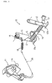
- Fig. 2 a view of a stand device of this embodiment in a set-back position
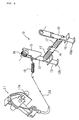
- Fig. 3 a view of the stand device at an erected position when the vehicle body is stood up with the rear wheel grounded
- Fig. 4 a view of the stand device at an erected position when the vehicle body is stood up with the rear wheel floated
- Fig. 5 views of the motorcycle according to this embodiment, (A) with the stand device in a set-back position, (B) with the vehicle body being stood up with the rear wheel grounded, and (C) with the vehicle body stood up with the rear wheel floated.
- the motorcycle with a stand device of this embodiment is a scooter type motorcycle, as shown in Fig. 1, in which low and wide steps 4 are formed between the handle 3 and a seat 3, and a driver rides the vehicle sitting on the seat 3 with his or her feet rested on the steps 4 and holding the grips of the handle 2 in a straightened-up fashion.
- a steering section including the handle 2, a steering shaft (not shown) as a rotation axis, and front forks 5, and to the lower ends of the left and right front forks 5 is fitted a front wheel 6 for rotation.
- Rearwardly of the steering section are provided wide steps 4 for the driver to rest his or her feet at a low position; to the rear of the steps 5 is disposed the seat 3 for a driver to sit on with his or her feet rested on the steps 4; downwardly of the seat 3 is mounted, to a body frame, an integrated power system unit 7 including an engine, a transmission, an air cleaner, etc, for swinging movement as a swinging arm, with a cushion unit 8, comprised of a hydraulic shock absorber and a coil spring, interposed; and a rear wheel 9 is fitted to the rear end of the power system unit 7 in a cantilever fashion.
- an integrated power system unit 7 including an engine, a transmission, an air cleaner, etc, for swinging movement as a swinging arm, with a cushion unit 8, comprised of a hydraulic shock absorber and a coil spring, interposed; and a rear wheel 9 is fitted to the rear end of the power system unit 7 in a cantilever fashion.
- a main stand 10 with a pair of left and right legs is provided at the forward bottom of the power system unit 7 for pivotal movement.
- a control section 11 for displacing the legs of the main stand to either of set-back and erected positions is fitted fixedly to the body frame such that it is exposed from a cover member covering the front of the vehicle body, at a location forwardly and upwardly of the steps 4, and displacement of the legs of the main stand 10 to set-back and erected positions is performed by remote control from the control section 11 through a cable.
- main stand 10 is mounted to the power system unit 7, this invention is not limited to that, and it may be attached to a body frame through mounting brackets.
- each of the left and right legs of the main stand 10 is comprised of a main leg 12 and a sub-leg 13, and the left and right legs 12 are connected integrally to each other by a cross pipe 14 and mounted pivotally to a body member (housing section of the power system unit 7) with unillustrated bolts through collars at mounting holes 12A formed at one ends thereof.
- the main leg 12 having one end mounted pivotally to a body member (housing section of the power system unit 7) is formed, at the other end, with a grounding foot 12b integrally, and the sub-leg 13 is mounted, at one end, to the main leg at a position inwardly of the grounding foot 12b, with a bolt through a collar, for pivotal movement only in the rearward direction from the stretched position in line with the main leg 12, the sub-leg 13 being formed, at the other end, with a grounding foot 13b integrally.
- a lever member 15 is coupled integrally to at least either of the left and right main legs 12 (to the right leg in the figure) ; the lower member 15 is adapted to come in contact with a stopper of a body member (housing section of the power system unit 7) to stop, at a given erected position, the forward pivotal movement of the main leg 12 from a set-back position; and a return spring 15 for biasing the main leg 12 toward the set-back position, that is, in an approximately horizontal and rearward direction, is fitted around the mounting hole 12a passing through the connecting section of the main leg 12 and the lever member 15, with one end engaged with a body member (housing section of the power system unit 7) and the other end engaged with the lever member 15.
- a pair of left and right torsion springs 17 are fitted on the cross pipe 14, with one ends engaged with the cross pipe 17 and the other ends engaged with the sub-legs 13.
- a compression spring for pushing the head of the sub-leg 13 (on the pivot shaft side) is inserted in the cylindrical portion of each main leg 13 at a position inwardly of the pivot of the sub-leg 13 (forwardly of the pivot in the set-back position and upwardly of the pivot in the erected position) to provide reliable locking of the sub-leg 13 at either of stretched and rearwardly turned positions.
- the stand device of this embodiment comprised of the main stand 10 and the control section 11 as described above, when the control lever 11a is shifted upwardly to a free position of the control section 11 to loosen the cable 20, the main legs 12 are turned rearwardly to the horizontally extending set-back position by the bias force of the return spring 16, and the sub-legs 13 are stretched in line with the main legs 12 by the bias force of the torsion springs 17, as shown in Fig. 2.
- the vehicle body of the motorcycle 1 cannot be stood up at the time of stoppage because of the main stand 10 being in the set-back position with respect to the vehicle body.
- the grounding feet 12b of the main legs 12 come in contact with the ground before the main legs 12 reach the given erected position, that is, before the main legs 12 pass right under the mounting point (pivot of the main legs 12).
- the driver while on the vehicle, puts his or her feet down on the ground and pulls slightly the vehicle body backward, the main legs 12 are stopped at the given erected position after passing right under the mounting point (pivot of the main legs 12).
- the main stand 10 supporting the vehicle body in either case of the vehicle body being stood up with the rear wheel grounded and floated, the main stand 10 supporting the vehicle body is in the same given erected position and the relation between the center of gravity of the vehicle and the grounding position of the main stand 10 doesn't change significantly, so that the vehicle body can be stood up stably in either case, at an optimum erected position of the main stand 10, and when the standing condition of the vehicle body is shifted from a condition in which the rear wheel is grounded to a condition in which the rear wheel is floated, it can be changed by simple actions of tilting the vehicle body to the left and right sides with a small force.
- the main legs 12 can be displaced to set-back and erected positions by remote control from the control section 11 through the cable 20 and the coil spring 18 using the control lever 11 a, so that if a driver on the vehicle manipulates the control lever 11 a of the control section 11 without alighting from the vehicle, the driver can stand up the vehicle body (with the rear wheel grounded) immediately after stoppage of running, or can start the vehicle after getting on the vehicle in a standing condition with the rear wheel grounded.
- this invention is not limited to that, and may be applied, for example, in addition to a scooter type motorcycle, to other types of motorcycles.
- this invention is not necessarily limited to the type in which the legs are displaced to setback and erected positions by remote control through the cable, and also for the structure of the main stand, this invention is not limited to that shown specifically in the figure. As such, it should be understood that changes and modifications may be made as appropriate without departing from the scope of the invention.
- the vehicle body in either case of the vehicle body being stood up with the rear wheel grounded and floated, the vehicle body can be stood up stably at all times at an optimum erected position of the stand legs, and when the standing condition of the vehicle is shifted from a condition in which the rear wheel is grounded to a condition in which the rear wheel is floated, it can be changed easily by simple actions with a small force
- each of said pair of left and right legs comprises a main leg having one end pivotally mounted to a body member for displacement to either of setback and erected positions and a sub-leg connected to said main leg near the other end for pivotal movement, said main leg being configured such that it has a length enough to stand up the vehicle body with a rear wheel grounded at said erected position, and said sub-leg being biased toward a stretched position in line with said main leg and connected to said main leg for rearward pivotal movement against said bias force.
- left and right sub-legs are connected to said integrally coupled left and right main legs for independent pivotal movement, respectively.
- main leg is adapted to be displaced to set-back and erected positions by remote control, through a cable and a coil spring, from a control section provided on a desirable location of the vehicle body.
Landscapes
- Engineering & Computer Science (AREA)
- Mechanical Engineering (AREA)
- Motorcycle And Bicycle Frame (AREA)
- Vehicle Cleaning, Maintenance, Repair, Refitting, And Outriggers (AREA)
Claims (9)
- Ständervorrichtung für ein Zweiradfahrzeug, insbesondere ein Motorrad, das einen Hauptständer (10) hat, mit einem Paar von linken und rechten Schenkeln, wobei jeder der linken und rechten Schenkel einen Schenkelabschnitt (12) aufweist, der mit dem Fahrzeug zwischen einer Zurücksetzposition und einer Aufrichtposition schwenkbar verbindbar ist, und einen Unter- Schenkelabschnitt (13), der schwenkbar mit dem Haupt- Schenkelabschnitt verbunden ist, dadurch gekennzeichnet, dass eine Länge des Haupt- Schenkelabschnittes (12) derart festgelegt wird, dass der Haupt- Schenkelabschnitt (12) in der Lage ist, zwischen der Zurücksetzposition und der Aufrichtposition zu schwenken, um eine Fahrzeugkarosserie mit einem Hinterrad (9), das den Boden berührt, aufzustellen.
- Ständervorrichtung nach Anspruch 1, dadurch gekennzeichnet, dass der Haupt- Schenkelabschnitt (12) jedes der linken und rechten Schenkel mit einem Endabschnitt desselben mit einem Gehäuseabschnitt der Antriebssystemeinheit (7) oder einem Karosserierahmen des Fahrzeuges für die Verlagerung in entweder die Zurücksetzposition oder die Aufrichtposition montierbar ist, wobei das jeweils andere Ende des Haupt- Schenkelabschnittes (12) einstückig einen Bodenaufsetzfuß (12b) aufweist.
- Ständervorrichtung nach Anspruch 2, dadurch gekennzeichnet, dass der Unter-Schenkelabschnitt (13) mit dem jeweiligen Haupt- Schenkelabschnitt (12) nahe des Endes des Haupt- Schenkelabschnittes (12), der den Bodenaufsetzfuß (12b) aufweist, verbunden ist, wobei der Unter- Schenkelabschnitt (13) an dem Haupt-Schenkelabschnitt (12) an einer Position einwärts des Bodenaufsetzfußes (12b) montiert ist.
- Ständervorrichtung nach zumindest einem der vorhergehenden Ansprüche 1 bis 3, dadurch gekennzeichnet, dass der Unter- Schenkelabschnitt (13) von jedem des linken und rechten Schenkels in die Richtung zu der gestreckten Position in einer Linie mit dem jeweiligen Haupt- Schenkelabschnitt (12) durch eine Vorspannkraft von zumindest einem Federteil (17) vorgespannt ist und mit dem Haupt- Schenkelabschnitt (12) für eine Rückwärts- Schwenkbewegung aus der gestreckten Position entgegen die Vorspannkraft verbunden ist.
- Ständervorrichtung nach zumindest einem der vorhergehenden Ansprüche 1 bis 4, dadurch gekennzeichnet, dass die Haupt- Schenkelabschnitte (12) des Paares des linken und rechten Schenkels des Hauptständers (10) miteinander einstückig gekuppelt sind, wobei die Unter- Schenkelabschnitte (13)jeweils mit dem integralen linken und rechten Schenkel (12) zur unabhängigen Schwenkbewegung gekuppelt sind.
- Ständervorrichtung nach zumindest einem der vorhergehenden Ansprüche 1 bis 5, gekennzeichnet durch ein Steuerungsteil (11) zum Steuern einer Verlagerung des Hauptständers (10) zwischen der Zurücksetzposition und der Aufrichtposition der Haupt- Schenkelabschnitte (12) des Paares der linken und rechten Schenkel des Hauptständers (10), wobei das Steuerungsteil in einem Ort platziert ist, der von dem Hauptständer (10) entfernt ist.
- Ständervorrichtung nach Anspruch 6, dadurch gekennzeichnet, dass das Steuerungsteil (11) mit zumindest einem der Haupt- Schenkelabschnitte (12) des Hauptständers (10) durch ein Kabel (20) und ein Federteil (18) verbunden ist.
- Ständervorrichtung nach zumindest einem der vorhergehenden Ansprüche 1 bis 7, gekennzeichnet durch ein Hebelteil (15), einstückig gekuppelt mit zumindest einem der Haupt- Schenkelabschnitte (12) des linken und rechten Schenkels des Hauptständers (10), wobei das Hebelteil (15) vorgesehen ist eine Vorwärts-Schwenkbewegung der Haupt- Schenkelabschnitte (12) aus der Rücksetzposition in die aufgerichtete Position an einer vorbestimmten Position zu stoppen.
- Ständervorrichtung nach zumindest einem der vorhergehenden Ansprüche 1 bis 8, gekennzeichnet durch eine Rückholfeder (16) zum Vorspannen der Haupt-Schenkelabschnitte (12) in die Richtung zu der Rücksetzposition.
Applications Claiming Priority (2)
| Application Number | Priority Date | Filing Date | Title |
|---|---|---|---|
| JP2000341282 | 2000-11-09 | ||
| JP2000341282A JP2002145141A (ja) | 2000-11-09 | 2000-11-09 | 自動二輪車のスタンド装置 |
Publications (3)
| Publication Number | Publication Date |
|---|---|
| EP1205378A2 EP1205378A2 (de) | 2002-05-15 |
| EP1205378A3 EP1205378A3 (de) | 2004-01-14 |
| EP1205378B1 true EP1205378B1 (de) | 2006-07-12 |
Family
ID=18816046
Family Applications (1)
| Application Number | Title | Priority Date | Filing Date |
|---|---|---|---|
| EP20010126792 Expired - Lifetime EP1205378B1 (de) | 2000-11-09 | 2001-11-09 | Standvorrichtung für ein Zweiradfahrzeug |
Country Status (6)
| Country | Link |
|---|---|
| EP (1) | EP1205378B1 (de) |
| JP (1) | JP2002145141A (de) |
| CN (1) | CN1254398C (de) |
| DE (1) | DE60121406T2 (de) |
| ES (1) | ES2267651T3 (de) |
| TW (1) | TW504476B (de) |
Families Citing this family (3)
| Publication number | Priority date | Publication date | Assignee | Title |
|---|---|---|---|---|
| DE102008039423B4 (de) * | 2008-08-23 | 2014-01-16 | Jens Krause | Parkvorrichtung |
| DE102009006008B4 (de) * | 2009-01-23 | 2010-11-11 | Adrian Floryszczak | Motorradständer |
| CN102951223A (zh) * | 2012-11-20 | 2013-03-06 | 宁波恒隆车业有限公司 | 一种自行车停车架 |
Family Cites Families (2)
| Publication number | Priority date | Publication date | Assignee | Title |
|---|---|---|---|---|
| DE581754C (de) * | 1933-08-02 | Kurt Rill | Schwenkbarer, zweistufiger Kippstaender fuer Motorraeder | |
| JPS5110536A (de) | 1974-07-16 | 1976-01-28 | Kuniaki Myazawa |
-
2000
- 2000-11-09 JP JP2000341282A patent/JP2002145141A/ja active Pending
-
2001
- 2001-07-11 CN CN 01122856 patent/CN1254398C/zh not_active Expired - Fee Related
- 2001-10-05 TW TW90124672A patent/TW504476B/zh active
- 2001-11-09 EP EP20010126792 patent/EP1205378B1/de not_active Expired - Lifetime
- 2001-11-09 ES ES01126792T patent/ES2267651T3/es not_active Expired - Lifetime
- 2001-11-09 DE DE2001621406 patent/DE60121406T2/de not_active Expired - Fee Related
Also Published As
| Publication number | Publication date |
|---|---|
| ES2267651T3 (es) | 2007-03-16 |
| TW504476B (en) | 2002-10-01 |
| JP2002145141A (ja) | 2002-05-22 |
| CN1254398C (zh) | 2006-05-03 |
| DE60121406D1 (de) | 2006-08-24 |
| EP1205378A2 (de) | 2002-05-15 |
| EP1205378A3 (de) | 2004-01-14 |
| DE60121406T2 (de) | 2006-11-23 |
| CN1353064A (zh) | 2002-06-12 |
Similar Documents
| Publication | Publication Date | Title |
|---|---|---|
| US4087107A (en) | Cambering vehicle with trailing arm seat for vehicle operator | |
| US6631925B1 (en) | Miniaturized motor vehicle | |
| JP2656327B2 (ja) | 三輪車の操舵方法及びその機構 | |
| AU2018268403B2 (en) | Integrated park brake system for a riding lawn care vehicle | |
| US5388848A (en) | Motorcycle kick stand | |
| CA1067533A (en) | Lock bar for cambering vehicle | |
| AU2001238273A1 (en) | Miniaturized motor vehicle | |
| US20070018423A1 (en) | Recumbent vehicle | |
| US20020089138A1 (en) | Scooter steering control | |
| AU2018288056B2 (en) | Deck lift assembly for a riding lawn care vehicle | |
| US20080157503A1 (en) | Main stand for motorcycle | |
| EP1854710B1 (de) | Motorradständer | |
| US6478104B1 (en) | Collapsible motor driven vehicle | |
| EP1205378A2 (de) | Standvorrichtung für ein Zweiradfahrzeug | |
| US20020089139A1 (en) | Scooter steering control | |
| GB2277062A (en) | A chassis | |
| EP0970881A2 (de) | Fahrrad mit Lenkeranordnung | |
| US20030173756A1 (en) | Steering assist apparatus, a vehicle using the steering assist apparatus and a method for steering | |
| JP4495642B2 (ja) | 乗用田植機 | |
| JP4664886B2 (ja) | 二輪車のブレーキ・スタンド連動装置 | |
| JP4566829B2 (ja) | 乗用田植機 | |
| JP4913364B2 (ja) | 作業車両のシート | |
| JP2004051017A (ja) | トレーラ付き車両 | |
| JP3102528B2 (ja) | 車両用棒状ハンドル | |
| JP2008512305A (ja) | 自走式の食料品ないし飲料品の収蔵容器 |
Legal Events
| Date | Code | Title | Description |
|---|---|---|---|
| PUAI | Public reference made under article 153(3) epc to a published international application that has entered the european phase |
Free format text: ORIGINAL CODE: 0009012 |
|
| AK | Designated contracting states |
Kind code of ref document: A2 Designated state(s): AT BE CH CY DE DK ES FI FR GB GR IE IT LI LU MC NL PT SE TR |
|
| AX | Request for extension of the european patent |
Free format text: AL;LT;LV;MK;RO;SI |
|
| PUAL | Search report despatched |
Free format text: ORIGINAL CODE: 0009013 |
|
| AK | Designated contracting states |
Kind code of ref document: A3 Designated state(s): AT BE CH CY DE DK ES FI FR GB GR IE IT LI LU MC NL PT SE TR |
|
| AX | Request for extension of the european patent |
Extension state: AL LT LV MK RO SI |
|
| RIC1 | Information provided on ipc code assigned before grant |
Ipc: 7B 62H 1/06 B Ipc: 7B 62H 1/02 A |
|
| 17P | Request for examination filed |
Effective date: 20040113 |
|
| AKX | Designation fees paid |
Designated state(s): DE ES FR GB IT |
|
| GRAP | Despatch of communication of intention to grant a patent |
Free format text: ORIGINAL CODE: EPIDOSNIGR1 |
|
| RIN1 | Information on inventor provided before grant (corrected) |
Inventor name: YAMADA, KAZUNORI Inventor name: KISHIMOTO, EIJI Inventor name: TAKADA, KAZUYOSHI |
|
| GRAS | Grant fee paid |
Free format text: ORIGINAL CODE: EPIDOSNIGR3 |
|
| GRAA | (expected) grant |
Free format text: ORIGINAL CODE: 0009210 |
|
| AK | Designated contracting states |
Kind code of ref document: B1 Designated state(s): DE ES FR GB IT |
|
| PG25 | Lapsed in a contracting state [announced via postgrant information from national office to epo] |
Ref country code: IT Free format text: LAPSE BECAUSE OF FAILURE TO SUBMIT A TRANSLATION OF THE DESCRIPTION OR TO PAY THE FEE WITHIN THE PRESCRIBED TIME-LIMIT;WARNING: LAPSES OF ITALIAN PATENTS WITH EFFECTIVE DATE BEFORE 2007 MAY HAVE OCCURRED AT ANY TIME BEFORE 2007. THE CORRECT EFFECTIVE DATE MAY BE DIFFERENT FROM THE ONE RECORDED. Effective date: 20060712 |
|
| REG | Reference to a national code |
Ref country code: GB Ref legal event code: FG4D |
|
| REF | Corresponds to: |
Ref document number: 60121406 Country of ref document: DE Date of ref document: 20060824 Kind code of ref document: P |
|
| ET | Fr: translation filed | ||
| REG | Reference to a national code |
Ref country code: ES Ref legal event code: FG2A Ref document number: 2267651 Country of ref document: ES Kind code of ref document: T3 |
|
| PLBE | No opposition filed within time limit |
Free format text: ORIGINAL CODE: 0009261 |
|
| STAA | Information on the status of an ep patent application or granted ep patent |
Free format text: STATUS: NO OPPOSITION FILED WITHIN TIME LIMIT |
|
| 26N | No opposition filed |
Effective date: 20070413 |
|
| PGFP | Annual fee paid to national office [announced via postgrant information from national office to epo] |
Ref country code: DE Payment date: 20081107 Year of fee payment: 8 |
|
| PGFP | Annual fee paid to national office [announced via postgrant information from national office to epo] |
Ref country code: ES Payment date: 20081216 Year of fee payment: 8 |
|
| PGFP | Annual fee paid to national office [announced via postgrant information from national office to epo] |
Ref country code: IT Payment date: 20081126 Year of fee payment: 8 |
|
| PGFP | Annual fee paid to national office [announced via postgrant information from national office to epo] |
Ref country code: FR Payment date: 20081112 Year of fee payment: 8 |
|
| PGFP | Annual fee paid to national office [announced via postgrant information from national office to epo] |
Ref country code: GB Payment date: 20081105 Year of fee payment: 8 |
|
| GBPC | Gb: european patent ceased through non-payment of renewal fee |
Effective date: 20091109 |
|
| REG | Reference to a national code |
Ref country code: FR Ref legal event code: ST Effective date: 20100730 |
|
| PG25 | Lapsed in a contracting state [announced via postgrant information from national office to epo] |
Ref country code: FR Free format text: LAPSE BECAUSE OF NON-PAYMENT OF DUE FEES Effective date: 20091130 |
|
| PG25 | Lapsed in a contracting state [announced via postgrant information from national office to epo] |
Ref country code: DE Free format text: LAPSE BECAUSE OF NON-PAYMENT OF DUE FEES Effective date: 20100601 |
|
| PG25 | Lapsed in a contracting state [announced via postgrant information from national office to epo] |
Ref country code: GB Free format text: LAPSE BECAUSE OF NON-PAYMENT OF DUE FEES Effective date: 20091109 |
|
| REG | Reference to a national code |
Ref country code: ES Ref legal event code: FD2A Effective date: 20110309 |
|
| PG25 | Lapsed in a contracting state [announced via postgrant information from national office to epo] |
Ref country code: IT Free format text: LAPSE BECAUSE OF NON-PAYMENT OF DUE FEES Effective date: 20091109 |
|
| PG25 | Lapsed in a contracting state [announced via postgrant information from national office to epo] |
Ref country code: ES Free format text: LAPSE BECAUSE OF NON-PAYMENT OF DUE FEES Effective date: 20110308 |
|
| PG25 | Lapsed in a contracting state [announced via postgrant information from national office to epo] |
Ref country code: ES Free format text: LAPSE BECAUSE OF NON-PAYMENT OF DUE FEES Effective date: 20091110 |