EP1205604B1 - Procédé et installation de récupération d'une nappe flottant à la surface d'une liquide - Google Patents
Procédé et installation de récupération d'une nappe flottant à la surface d'une liquide Download PDFInfo
- Publication number
- EP1205604B1 EP1205604B1 EP01402813A EP01402813A EP1205604B1 EP 1205604 B1 EP1205604 B1 EP 1205604B1 EP 01402813 A EP01402813 A EP 01402813A EP 01402813 A EP01402813 A EP 01402813A EP 1205604 B1 EP1205604 B1 EP 1205604B1
- Authority
- EP
- European Patent Office
- Prior art keywords
- enclosure
- product
- vortex
- installation
- outlet
- Prior art date
- Legal status (The legal status is an assumption and is not a legal conclusion. Google has not performed a legal analysis and makes no representation as to the accuracy of the status listed.)
- Expired - Lifetime
Links
- 238000007667 floating Methods 0.000 title claims abstract description 19
- 239000007788 liquid Substances 0.000 title description 26
- 238000000034 method Methods 0.000 title description 7
- 230000008569 process Effects 0.000 title description 4
- XLYOFNOQVPJJNP-UHFFFAOYSA-N water Substances O XLYOFNOQVPJJNP-UHFFFAOYSA-N 0.000 claims description 21
- 238000005188 flotation Methods 0.000 claims description 4
- 238000007654 immersion Methods 0.000 claims description 3
- 230000004907 flux Effects 0.000 claims 1
- 239000000126 substance Substances 0.000 abstract 2
- 239000000047 product Substances 0.000 description 40
- 238000009434 installation Methods 0.000 description 37
- 238000011084 recovery Methods 0.000 description 14
- 239000012530 fluid Substances 0.000 description 6
- 239000002245 particle Substances 0.000 description 6
- 238000005086 pumping Methods 0.000 description 6
- 230000003068 static effect Effects 0.000 description 6
- 230000000694 effects Effects 0.000 description 4
- 239000007787 solid Substances 0.000 description 3
- 241000218636 Thuja Species 0.000 description 2
- 230000004888 barrier function Effects 0.000 description 2
- 238000010586 diagram Methods 0.000 description 2
- 239000012265 solid product Substances 0.000 description 2
- 239000002352 surface water Substances 0.000 description 2
- 230000009471 action Effects 0.000 description 1
- 230000008901 benefit Effects 0.000 description 1
- 230000008859 change Effects 0.000 description 1
- 239000012141 concentrate Substances 0.000 description 1
- 239000003344 environmental pollutant Substances 0.000 description 1
- 239000013505 freshwater Substances 0.000 description 1
- 239000000203 mixture Substances 0.000 description 1
- 235000011837 pasties Nutrition 0.000 description 1
- 230000035515 penetration Effects 0.000 description 1
- 239000003208 petroleum Substances 0.000 description 1
- 231100000719 pollutant Toxicity 0.000 description 1
- 238000011027 product recovery Methods 0.000 description 1
- 238000007790 scraping Methods 0.000 description 1
- 239000013535 sea water Substances 0.000 description 1
- 238000009987 spinning Methods 0.000 description 1
- 239000003643 water by type Substances 0.000 description 1
- 238000003911 water pollution Methods 0.000 description 1
Images

Classifications
-
- E—FIXED CONSTRUCTIONS
- E02—HYDRAULIC ENGINEERING; FOUNDATIONS; SOIL SHIFTING
- E02B—HYDRAULIC ENGINEERING
- E02B15/00—Cleaning or keeping clear the surface of open water; Apparatus therefor
- E02B15/04—Devices for cleaning or keeping clear the surface of open water from oil or like floating materials by separating or removing these materials
- E02B15/10—Devices for removing the material from the surface
- E02B15/107—Whirling means forming a vortex in the water; cyclones
-
- Y—GENERAL TAGGING OF NEW TECHNOLOGICAL DEVELOPMENTS; GENERAL TAGGING OF CROSS-SECTIONAL TECHNOLOGIES SPANNING OVER SEVERAL SECTIONS OF THE IPC; TECHNICAL SUBJECTS COVERED BY FORMER USPC CROSS-REFERENCE ART COLLECTIONS [XRACs] AND DIGESTS
- Y02—TECHNOLOGIES OR APPLICATIONS FOR MITIGATION OR ADAPTATION AGAINST CLIMATE CHANGE
- Y02A—TECHNOLOGIES FOR ADAPTATION TO CLIMATE CHANGE
- Y02A20/00—Water conservation; Efficient water supply; Efficient water use
- Y02A20/20—Controlling water pollution; Waste water treatment
- Y02A20/204—Keeping clear the surface of open water from oil spills
-
- Y—GENERAL TAGGING OF NEW TECHNOLOGICAL DEVELOPMENTS; GENERAL TAGGING OF CROSS-SECTIONAL TECHNOLOGIES SPANNING OVER SEVERAL SECTIONS OF THE IPC; TECHNICAL SUBJECTS COVERED BY FORMER USPC CROSS-REFERENCE ART COLLECTIONS [XRACs] AND DIGESTS
- Y10—TECHNICAL SUBJECTS COVERED BY FORMER USPC
- Y10S—TECHNICAL SUBJECTS COVERED BY FORMER USPC CROSS-REFERENCE ART COLLECTIONS [XRACs] AND DIGESTS
- Y10S210/00—Liquid purification or separation
- Y10S210/918—Miscellaneous specific techniques
- Y10S210/922—Oil spill cleanup, e.g. bacterial
- Y10S210/923—Oil spill cleanup, e.g. bacterial using mechanical means, e.g. skimmers, pump
Definitions
- the present invention relates to an installation recovery of a floating sheet on the surface of the water such as an oil slick as defined in the preamble of the first claim.
- recuperators are classified in two types, mechanical recuperators using fluid flow properties and the density of the liquid to recover and oleophilic recuperators intended especially to oil recovery and who use the properties of adhesion of oil on surfaces brought in contact with water and pollutant.
- Oleophilic recuperators are, in general, constituted by a set of disks, drums or a belt or rope equipment, which enter the tablecloth and take advantage of the adherence of oil on the structure discs, drums, straps or ropes for hang the product, transport it and evacuate it. The removal is usually done by scraping or spinning.
- a vortex recuperator constituted by a pumping head or strainer coming over the tablecloth to be pumped, at the level of it.
- a propeller creates a depression by forming a static vortex so as to accumulate the product less dense than water to concentrate it under the strainer.
- this installation uses a propeller to create, under the suction head, a pocket in which accumulates the liquid to be pumped.
- this installation is very delicate to use and is only suitable for fluid products in calm waters.
- This method and this installation do not allow not to pump partially solid products since pumping is from the top, in the opposite direction to the direction in which the static vortex creates depression forming the pocket.
- This process can not be used when the surface water is agitated because, then, the penetration of air into the pump head may defuse the pump.
- US 3,635,342 discloses an installation recovery of a floating oil slick on the surface some water.
- This installation has a recovery head formed of an enclosure whose upper part is provided with an entrance to receive the product to recover.
- This speaker is provided with a product outlet in the form of a suction tube, going up into the chamber until under entry.
- This enclosure is also equipped with a propeller immersed in the liquid of the enclosure to create a vortex descending to form a pocket of liquid to recover. This pocket is formed above the propeller.
- This installation which, a priori, should only recover the product of the pocket formed in the vortex, is a delicate adjustment because the product of the bag is pumped into it by a pump, the vortex simply creating the pocket since this vortex is formed mainly by water. This vortex does not propel the liquid to recover in the pipe, the recovery being only by the pump.
- This installation does not have for purpose of precisely separating the liquid to be recovered water on which it floats because the installation is hooked at the bottom of the water.
- this installation creates the effect of vortex or suction venturi, in different modes envisaged, a pocket in the water, pocket in which happens the liquid to be recovered to be pumped in this pocket.
- these two embodiments have in common a funnel-shaped recovery head whose entrance is equipped with blades, spiral, to promote regularity of the arrival of the product in this recovery head in funnel shape.
- the end bottom of this funnel is connected to a pipe suction.
- this end is clogged to form a tarpaulin in which plunges a suction pump, recovering the liquid at this point.
- the present invention aims to remedy disadvantages of known solutions and proposes to develop an installation allowing to pump extremely effective layers of product floating on the surface of water and this regardless of the physical nature of the products (fluid, semi-fluid or even partially solidified state), and whatever the characteristics of the place of the floating water table, whether subject to swell, wind, surface currents or where the tablecloth without pumping the water on which these tablecloths float to increase the efficiency of recovery.
- the invention relates to an installation according to the characteristics of the characterizing part of the first claim.
- the vortex according to the invention circulates the flow of product taken from the sheet to evacuate it.
- the installation generates a dynamic vortex, that is to say a vortex that produces a circulation of fluid from up and down, from the collector's entrance to its exit and not a simple static depression creating a charged pocket product of lower density than that of the liquid in which normally floats the slick of product, that is to say freshwater or seawater.
- This aspiration will then be added to the impetus communicated to the fluid at the level of the vortex.
- Product recovery can be done from a very largely independent of the physical nature of the recovered product, whether it is liquid, more or less pasty or even if it contains particles or parts solid.
- the installation makes it possible to recover even particles floating solids on the surface of the slick, since these particles will be entrained in the vortex and from there evacuated.
- the propeller creating the vortex is immersed at an adjustable height in the enclosure of the floating web, which allows to adapt the vortex effect to the nature of the products to be recovered.
- the hopper or funnel shape of the enclosure promotes the flow of the product web in the vortex, without creating dead zones that would be occupied by the product or water.
- connection between the floats and the enclosure is adjustable to adjust the immersion depth of the entrance of the enclosure according to the thickness of the tablecloth of product to recover without sucking the water.
- This floating installation of the installation allows to follow the variations of height of the tablecloth depending on the swell.
- the output of the enclosure is connected to an evacuation pipe equipped with a means suction.
- This vent pipe may have some degree of length depending on the layout of different means of the installation and in particular of the recovery head and reservoirs collecting the product.
- control unit is connected to the generator motor vortex and suction means to coordinate the operation these two means and allow optimum performance.
- the formed flotation means of floats carrying the enclosure and the vortex generator does not constitute a closed barrier placed above the enclosure or surrounding it. On the contrary, it is only separate points of support leaving passages between them to allow not only the slick but also on the surface of the sheet to penetrate the enclosure to be taken by the vortex.
- the installation according to the invention constitutes an extremely simple means of work, likely to work in extreme conditions both for the situation of the sheet to be recovered or the nature of the products.
- the installation is particularly simple to maintain, to implement and it is compact.
- FIG. 1 a known installation known as vortex, mechanical recovery of product P floating under the shape of a sheet on the surface of the water E, is composed of a suction head 100 placed on the surface of the sheet P.
- This suction head 100 comprises a propeller 101, driven by a motor not shown, is housed in a box 102 trumpet-shaped surrounding the helix 101.
- the propeller 101 creates a depression inside the casing 102 to form a pocket 103 under the entrance 104 of the head 100, to accumulate a product thickness P allowing pumping.
- Product P is pumped as indicated arrows F1, F2.
- the propeller 101 creates a kind of static vortex forming the pocket in which accumulates product P; This can then be sucked. But as already indicated this aspiration is opposed to the aspiration created by the static vortex.
- the present invention relates to an installation as shown in FIGS. 2 and 3 and in the position of operation in Figure 4.
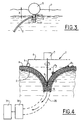
- the installation consists of a recovery head 1, formed of an enclosure 2 having at the top, an entry 3 and at the bottom, an exit 4.
- This head 1 is carried by a flotation means constituted by floats 5 integral with a chassis 6.
- the chassis 6 also carries a motor 7 whose shaft 8 is provided with a helix 9 constituting a vortex generator.
- This propeller 9 creates a dynamic vortex in the enclosure 2 which preferably has a trumpet shape along the flow lines of a vortex.
- the enclosure 2 is connected to the frame 5, 6 by via link members 10, of adjustable length. These connecting members are shown connected to the floats 5. They could also be directly connected to the 6. These connecting members 10 of adjustable length allow to change the depth (e) of immersion of the edge of the enclosure 2 constituting the input 3. This adjustment is made in function of the thickness X of the sheet of product P to be recovered (see Figure 3).
- a threaded rod 11 connected to the float 5 and provided with of a nut 12 to hold the edge 13 of the enclosure 2. On thus defines the height (e) of the opening 3.
- Figure 4 shows the installation according to the invention in use position.
- the recovery head is placed in a tablecloth P product and relies on the tablecloth, and more generally to the surface of the liquid, through its floats 5.
- These floats 5 do not constitute a ring surrounding the above the enclosure 2 but they form supports distributed at the surface of the slick or liquid as indicated in FIG. 4, in which, unlike FIG. right float 5 was not shown.
- the float (s) 5 do not constitute a closed barrier extending over above the entrance to the speaker 2 so as not to force the sheet of product P to necessarily pass under all floats 5.
- propeller 9 not only creates a depression in the chamber 2 but a vortex V, schematized in Figure 4, which arrives at least until Exit 4 of the enclosure 2.
- This dynamic vortex sucks up the upper layer of the liquid in which the recovery head 1 floats and which is mainly constituted by the layer of product P.
- the output 4 of the enclosure 2 is connected to a pipe 20 for the evacuation of the product.
- This conduct 20 is preferably connected to a pump 30 which delivers the liquid to a tank 31.
Landscapes
- Engineering & Computer Science (AREA)
- General Engineering & Computer Science (AREA)
- Environmental & Geological Engineering (AREA)
- Mechanical Engineering (AREA)
- Civil Engineering (AREA)
- Structural Engineering (AREA)
- Cleaning Or Clearing Of The Surface Of Open Water (AREA)
- Removal Of Floating Material (AREA)
- Treatment Of Fiber Materials (AREA)
- Photosensitive Polymer And Photoresist Processing (AREA)
- Electrolytic Production Of Metals (AREA)
- Processing And Handling Of Plastics And Other Materials For Molding In General (AREA)
- Structures Of Non-Positive Displacement Pumps (AREA)
Description
- la figure 1 est un schéma d'une installation connue,
- la figure 2 est un schéma de l'installation selon l'invention,
- la figure 3 montre un détail de l'installation de la figure 2,
- la figure 4 montre l'installation selon l'invention en position de fonctionnement.
Claims (5)
- Installation de récupération du produit formant une nappe flottant à la surface de l'eau telle qu'une nappe de pétrole, comprenantcaractérisée en ce queune tête de récupération (1) formée d'une enceinte (2) ayant une entrée (3), en partie haute pour le produit à récupérer et une sortie du produit récupéré,un générateur de vortex formé d'une hélice (9) immergée dans l'enceinte et portée par l'arbre (8) d'un moteur (7), créant dans l'enceinte un vortex (V) descendant ,un moyen de flottaison (5) soutenant l'enceinte (2),une conduite (20) reliant l'enceinte à un réservoir (31),l'enceinte (2) est une trémie épousant les lignes de flux du vortex, dont la partie évasée constitue l'entrée (3) du produit, et en partie basse (4), le sommet du cône constitue la sortie (4), cette sortie étant reliée à la conduite d'évacuation (20), du produit récupéréle générateur de vortex forme un vortex dynamique descendant (V) dans l'enceinte (2) jusqu'à sa sortie, etla liaison (10) entre les flotteurs (5) et l'enceinte (2) est réglable pour régler la profondeur d'immersion de l'entrée (3) de l'enceinte en fonction de l'épaisseur (X) de la nappe de produit à récupérer (P).
- Installation selon la revendication 1,
caractérisée en ce que
l'hélice (9) est immergée à une hauteur réglable dans l'enceinte sous le niveau de la nappe flottante (P). - Installation selon la revendication 1,
caractérisée en ce que
la conduite d'évacuation (20) est reliée à un moyen d'aspiration (30). - Installation selon l'une quelconque des revendications 1 et 3,
caractérisée par
une unité de commande reliée au moteur (7) du générateur de vortex (7, 8, 9) et au moyen d'aspiration (30) pour commander ces deux moyens l'un en fonction de l'autre. - Installation selon la revendication 1,
caractérisée en ce que
le moyen de flottaison (5) est formé de flotteurs portant l'enceinte (2) et le générateur de vortex (7, 8, 9).
Applications Claiming Priority (2)
| Application Number | Priority Date | Filing Date | Title |
|---|---|---|---|
| FR0014385 | 2000-11-09 | ||
| FR0014385A FR2816339B1 (fr) | 2000-11-09 | 2000-11-09 | Procede et installation de recuperation d'une nappe flottant a la surface d'un liquide |
Publications (2)
| Publication Number | Publication Date |
|---|---|
| EP1205604A1 EP1205604A1 (fr) | 2002-05-15 |
| EP1205604B1 true EP1205604B1 (fr) | 2005-10-12 |
Family
ID=8856237
Family Applications (1)
| Application Number | Title | Priority Date | Filing Date |
|---|---|---|---|
| EP01402813A Expired - Lifetime EP1205604B1 (fr) | 2000-11-09 | 2001-10-30 | Procédé et installation de récupération d'une nappe flottant à la surface d'une liquide |
Country Status (10)
| Country | Link |
|---|---|
| US (1) | US6712958B2 (fr) |
| EP (1) | EP1205604B1 (fr) |
| JP (1) | JP4031230B2 (fr) |
| AT (1) | ATE306587T1 (fr) |
| DE (1) | DE60113944T2 (fr) |
| DZ (1) | DZ3128A1 (fr) |
| ES (1) | ES2250327T3 (fr) |
| FR (1) | FR2816339B1 (fr) |
| MX (1) | MXPA01011196A (fr) |
| TN (1) | TNSN01157A1 (fr) |
Families Citing this family (17)
| Publication number | Priority date | Publication date | Assignee | Title |
|---|---|---|---|---|
| JP4904134B2 (ja) * | 2006-12-06 | 2012-03-28 | 中国電力株式会社 | 懸濁物質採取方法及び懸濁物質採取装置 |
| US7947173B2 (en) * | 2009-03-29 | 2011-05-24 | Chung-Jung Deng | Seawater filter |
| CN102373697B (zh) | 2010-08-17 | 2015-02-18 | 张苓 | 一种水面收污泵 |
| US9120034B1 (en) | 2011-01-04 | 2015-09-01 | Stephen Richard Leventhal | Self-adjusting gravity separator and a method of using |
| US8066872B1 (en) * | 2011-04-28 | 2011-11-29 | International Spill Control LLC | Dual weir vortex skimmer |
| KR101276127B1 (ko) * | 2011-10-13 | 2013-06-18 | 대우조선해양 주식회사 | 해양구조물 용 기름 제거 장치 |
| RU2572765C1 (ru) * | 2014-12-17 | 2016-01-20 | Аскар Джамилевич Мингажев | Способ сбора нефти из-под ледяного покрова водоема |
| CN106801409A (zh) * | 2017-03-22 | 2017-06-06 | 武汉理工大学 | 一体式转轴吸油管 |
| CN108793318B (zh) * | 2017-04-27 | 2024-04-30 | 中国石油天然气集团公司 | 一种储油罐罐内浮油抽吸装置及方法 |
| CN107119647A (zh) * | 2017-06-21 | 2017-09-01 | 张思琪 | 潜浮式水面漂浮垃圾清理器 |
| CN108978607B (zh) * | 2018-03-23 | 2020-09-04 | 浙大宁波理工学院 | 一种基于云图的旋涡引流式大水池漂浮物清理装置 |
| CN108330940B (zh) * | 2018-03-23 | 2020-05-12 | 浙江大学宁波理工学院 | 一种基于云图的双旋涡引流式水池漂浮物清理装置 |
| CN111608155B (zh) * | 2018-05-23 | 2021-12-21 | 温州耐特尔自动化设备有限公司 | 一种水坝水面废弃物收集装置 |
| CN108824394B (zh) * | 2018-06-28 | 2020-06-12 | 谢文浩 | 一种用于河道浅水滩缓坡水动力漂浮垃圾的清理装置 |
| CN111392288A (zh) * | 2020-04-11 | 2020-07-10 | 山西尚风科技股份有限公司 | 一种水上垃圾桶 |
| CN111893974A (zh) * | 2020-08-07 | 2020-11-06 | 湖南富高农业科技开发有限公司 | 一种养殖塘漂浮垃圾清除装置 |
| CN112392014A (zh) * | 2020-09-30 | 2021-02-23 | 贵州福兰科技有限公司 | 一种河流水污染防治用污染物隔离装置 |
Family Cites Families (16)
| Publication number | Priority date | Publication date | Assignee | Title |
|---|---|---|---|---|
| US1450545A (en) * | 1920-04-13 | 1923-04-03 | Oscar E Hans | Apparatus for separating liquids of different densities |
| US3534859A (en) * | 1969-03-11 | 1970-10-20 | Gulf Research Development Co | Apparatus for removal of oil floating on water or the like |
| US3635342A (en) * | 1969-12-22 | 1972-01-18 | Bertin & Cie | Method and apparatus for recovering a substance floating as a sheet on the surface of a liquid mass |
| US3693800A (en) * | 1970-12-14 | 1972-09-26 | Acme Products Inc | Floating surface skimmer |
| US3722689A (en) * | 1971-05-13 | 1973-03-27 | Reynolds Submarine Services Co | Apparatus for extracting oil or the like from the surface of the sea |
| CH556180A (de) * | 1971-09-15 | 1974-11-29 | Suhner Willy | Vorrichtung fuer das elastische festhalten von skibindungsteilen. |
| US3753496A (en) * | 1971-12-20 | 1973-08-21 | E Boyd | Converging vortex apparatus for separating oil from water |
| BE793184A (fr) * | 1972-01-19 | 1973-04-16 | Bagnulo Luigi | Dispositif hydraulique flottant pour la recuperation de produits petroliers poluant les eaux de mer et interieures |
| US4024063A (en) * | 1973-02-15 | 1977-05-17 | Kabushiki Kaisha World Chemical | Floating-matter removing apparatus |
| FR2219672A5 (fr) * | 1973-02-26 | 1974-09-20 | Bertin & Cie | |
| US4111809A (en) * | 1973-12-11 | 1978-09-05 | Societe Generale De Constructions Electriques Et Mecaniques Alsthom | Device for the removal of a liquid layer on water |
| US4038182A (en) * | 1974-02-04 | 1977-07-26 | Richard Stuart Jenkins | Oil spill recovery method and apparatus |
| US4142972A (en) * | 1975-03-27 | 1979-03-06 | Scientific Associates, Inc. | Mechanism and method for recovering material from the surface of a liquid body |
| US5118412A (en) * | 1991-04-17 | 1992-06-02 | Schmidt Richard J | Fluid recovery apparatus |
| US5200066A (en) * | 1991-11-18 | 1993-04-06 | Jorgensen Adam A | Oil spill collecting device with vortex generator |
| SE506242C2 (sv) * | 1996-03-01 | 1997-11-24 | Alfa Laval Ab | Anordning för att avskilja ett ytskikt hos en vätska |
-
2000
- 2000-11-09 FR FR0014385A patent/FR2816339B1/fr not_active Expired - Lifetime
-
2001
- 2001-10-24 DZ DZ010070A patent/DZ3128A1/fr active
- 2001-10-30 DE DE60113944T patent/DE60113944T2/de not_active Expired - Lifetime
- 2001-10-30 EP EP01402813A patent/EP1205604B1/fr not_active Expired - Lifetime
- 2001-10-30 ES ES01402813T patent/ES2250327T3/es not_active Expired - Lifetime
- 2001-10-30 AT AT01402813T patent/ATE306587T1/de not_active IP Right Cessation
- 2001-11-05 MX MXPA01011196A patent/MXPA01011196A/es active IP Right Grant
- 2001-11-08 TN TNTNSN01157A patent/TNSN01157A1/fr unknown
- 2001-11-08 JP JP2001342775A patent/JP4031230B2/ja not_active Expired - Lifetime
- 2001-11-09 US US10/035,893 patent/US6712958B2/en not_active Expired - Lifetime
Also Published As
| Publication number | Publication date |
|---|---|
| DE60113944T2 (de) | 2006-06-22 |
| FR2816339A1 (fr) | 2002-05-10 |
| JP2002160693A (ja) | 2002-06-04 |
| FR2816339B1 (fr) | 2003-07-11 |
| MXPA01011196A (es) | 2004-05-21 |
| EP1205604A1 (fr) | 2002-05-15 |
| US20020104797A1 (en) | 2002-08-08 |
| US6712958B2 (en) | 2004-03-30 |
| TNSN01157A1 (fr) | 2003-04-03 |
| DZ3128A1 (fr) | 2004-09-25 |
| DE60113944D1 (de) | 2005-11-17 |
| ES2250327T3 (es) | 2006-04-16 |
| ATE306587T1 (de) | 2005-10-15 |
| JP4031230B2 (ja) | 2008-01-09 |
Similar Documents
| Publication | Publication Date | Title |
|---|---|---|
| EP1205604A1 (fr) | Procédé et installation de récupération d'une nappe flottant à la surface d'une liquide | |
| CA2044902C (fr) | Procede et dispositif de separation entre une phase fluide continue et une phase dispersee, et application | |
| FR2607403A1 (fr) | Procede et dispositif de separation d'une phase dispersee en emulsion ou en suspension dans une phase continue | |
| US20090206043A1 (en) | Method and a Device for Collection of Floating Waste on a Water Surface | |
| CN1229389A (zh) | 灌注型撇油装置和撇油方法 | |
| WO2016097380A1 (fr) | Système de prélèvement de sédiments sur un fond d'un milieu liquide | |
| CN103649416B (zh) | 抽吸式浮子和收集装置以及收集船 | |
| FR2566675A1 (fr) | Procede et dispositif d'admission de boue | |
| FR2521189A1 (fr) | Roues a godets et d'excavation pour dragues et excavatrices, et excavatrice munie d'une telle roue | |
| EP0040129B1 (fr) | Récupérateur de pétrole à grand débit pour la dépollution sur eaux agitées | |
| WO2021089955A1 (fr) | Dispositif de récupération de produits liquides et/ou solides surnageant à la surface d'un plan d'eau | |
| FR2645558A1 (fr) | Procede d'enlevement de petrole de la surface de l'eau et recipient collecteur | |
| EP0976434B1 (fr) | Séparateur de liquides non miscibles | |
| CH565905A5 (en) | Collecting oil slick from sea water - uses conduit dragged across water surface and trapping floating oil film | |
| FR2483878A1 (fr) | Structure flottante pour le nettoyage d'un plan d'eau | |
| WO2020043986A1 (fr) | Système de nettoyage d'un milieu aquatique, pour l'obtention d'un milieu aquatique dépollué d'éléments flottants | |
| FR3156279A1 (fr) | Système mobile d’aspiration de végétaux en suspension dans un liquide | |
| WO2009044074A2 (fr) | Procede de separation solide/liquide d'effluent et separateur pour sa mise en oeuvre | |
| EP4719885A1 (fr) | Dispositif d'aspiration d'elements en suspension dans un liquide | |
| EP4291723A1 (fr) | Dispositif de filtrage pour collecter des debris a la surface de plans d'eau | |
| FR2554007A1 (fr) | Procede et dispositif de separation des emulsions graisse-eau et/ou huile-eau | |
| WO2025131650A1 (fr) | Système déflecteur pour barrage hydraulique | |
| BE830586Q (fr) | Procede d'enlevement de la surface d'une nappe d'eau d'un liquide polluant de densite moindre et engin utilise. | |
| BE554651A (fr) | ||
| JP2005016105A (ja) | 固液分離装置及び浚渫工法 |
Legal Events
| Date | Code | Title | Description |
|---|---|---|---|
| PUAI | Public reference made under article 153(3) epc to a published international application that has entered the european phase |
Free format text: ORIGINAL CODE: 0009012 |
|
| AK | Designated contracting states |
Kind code of ref document: A1 Designated state(s): AT BE CH CY DE DK ES FI FR GB GR IE IT LI LU MC NL PT SE TR |
|
| AX | Request for extension of the european patent |
Free format text: AL;LT;LV;MK;RO;SI |
|
| 17P | Request for examination filed |
Effective date: 20021024 |
|
| AKX | Designation fees paid |
Designated state(s): AT BE CH CY DE DK ES FI FR GB GR IE IT LI LU MC NL PT SE TR |
|
| 17Q | First examination report despatched |
Effective date: 20040109 |
|
| GRAP | Despatch of communication of intention to grant a patent |
Free format text: ORIGINAL CODE: EPIDOSNIGR1 |
|
| GRAS | Grant fee paid |
Free format text: ORIGINAL CODE: EPIDOSNIGR3 |
|
| GRAA | (expected) grant |
Free format text: ORIGINAL CODE: 0009210 |
|
| RIN1 | Information on inventor provided before grant (corrected) |
Inventor name: DJELOUAH, SALAH |
|
| AK | Designated contracting states |
Kind code of ref document: B1 Designated state(s): AT BE CH CY DE DK ES FI FR GB GR IE IT LI LU MC NL PT SE TR |
|
| PG25 | Lapsed in a contracting state [announced via postgrant information from national office to epo] |
Ref country code: AT Free format text: LAPSE BECAUSE OF FAILURE TO SUBMIT A TRANSLATION OF THE DESCRIPTION OR TO PAY THE FEE WITHIN THE PRESCRIBED TIME-LIMIT Effective date: 20051012 Ref country code: FI Free format text: LAPSE BECAUSE OF FAILURE TO SUBMIT A TRANSLATION OF THE DESCRIPTION OR TO PAY THE FEE WITHIN THE PRESCRIBED TIME-LIMIT Effective date: 20051012 Ref country code: NL Free format text: LAPSE BECAUSE OF FAILURE TO SUBMIT A TRANSLATION OF THE DESCRIPTION OR TO PAY THE FEE WITHIN THE PRESCRIBED TIME-LIMIT Effective date: 20051012 Ref country code: IE Free format text: LAPSE BECAUSE OF FAILURE TO SUBMIT A TRANSLATION OF THE DESCRIPTION OR TO PAY THE FEE WITHIN THE PRESCRIBED TIME-LIMIT Effective date: 20051012 |
|
| REG | Reference to a national code |
Ref country code: GB Ref legal event code: FG4D Free format text: NOT ENGLISH |
|
| REG | Reference to a national code |
Ref country code: CH Ref legal event code: EP |
|
| PG25 | Lapsed in a contracting state [announced via postgrant information from national office to epo] |
Ref country code: IT Free format text: LAPSE BECAUSE OF NON-PAYMENT OF DUE FEES Effective date: 20051030 Ref country code: CY Free format text: LAPSE BECAUSE OF FAILURE TO SUBMIT A TRANSLATION OF THE DESCRIPTION OR TO PAY THE FEE WITHIN THE PRESCRIBED TIME-LIMIT Effective date: 20051030 |
|
| PG25 | Lapsed in a contracting state [announced via postgrant information from national office to epo] |
Ref country code: BE Free format text: LAPSE BECAUSE OF NON-PAYMENT OF DUE FEES Effective date: 20051031 Ref country code: MC Free format text: LAPSE BECAUSE OF NON-PAYMENT OF DUE FEES Effective date: 20051031 Ref country code: CH Free format text: LAPSE BECAUSE OF NON-PAYMENT OF DUE FEES Effective date: 20051031 Ref country code: LI Free format text: LAPSE BECAUSE OF NON-PAYMENT OF DUE FEES Effective date: 20051031 |
|
| REG | Reference to a national code |
Ref country code: IE Ref legal event code: FG4D Free format text: LANGUAGE OF EP DOCUMENT: FRENCH |
|
| REF | Corresponds to: |
Ref document number: 60113944 Country of ref document: DE Date of ref document: 20051117 Kind code of ref document: P |
|
| PG25 | Lapsed in a contracting state [announced via postgrant information from national office to epo] |
Ref country code: LU Free format text: LAPSE BECAUSE OF NON-PAYMENT OF DUE FEES Effective date: 20051212 |
|
| PG25 | Lapsed in a contracting state [announced via postgrant information from national office to epo] |
Ref country code: SE Free format text: LAPSE BECAUSE OF FAILURE TO SUBMIT A TRANSLATION OF THE DESCRIPTION OR TO PAY THE FEE WITHIN THE PRESCRIBED TIME-LIMIT Effective date: 20060112 Ref country code: DK Free format text: LAPSE BECAUSE OF FAILURE TO SUBMIT A TRANSLATION OF THE DESCRIPTION OR TO PAY THE FEE WITHIN THE PRESCRIBED TIME-LIMIT Effective date: 20060112 |
|
| GBT | Gb: translation of ep patent filed (gb section 77(6)(a)/1977) |
Effective date: 20060125 |
|
| REG | Reference to a national code |
Ref country code: GR Ref legal event code: EP Ref document number: 20050403882 Country of ref document: GR |
|
| NLV1 | Nl: lapsed or annulled due to failure to fulfill the requirements of art. 29p and 29m of the patents act | ||
| REG | Reference to a national code |
Ref country code: ES Ref legal event code: FG2A Ref document number: 2250327 Country of ref document: ES Kind code of ref document: T3 |
|
| REG | Reference to a national code |
Ref country code: IE Ref legal event code: FD4D |
|
| REG | Reference to a national code |
Ref country code: CH Ref legal event code: PL |
|
| PLBE | No opposition filed within time limit |
Free format text: ORIGINAL CODE: 0009261 |
|
| STAA | Information on the status of an ep patent application or granted ep patent |
Free format text: STATUS: NO OPPOSITION FILED WITHIN TIME LIMIT |
|
| PG25 | Lapsed in a contracting state [announced via postgrant information from national office to epo] |
Ref country code: FR Free format text: LAPSE BECAUSE OF NON-PAYMENT OF DUE FEES Effective date: 20060831 |
|
| 26N | No opposition filed |
Effective date: 20060713 |
|
| REG | Reference to a national code |
Ref country code: FR Ref legal event code: ST Effective date: 20060831 |
|
| BERE | Be: lapsed |
Owner name: SORELEC Effective date: 20051031 |
|
| PG25 | Lapsed in a contracting state [announced via postgrant information from national office to epo] |
Ref country code: FR Free format text: LAPSE BECAUSE OF NON-PAYMENT OF DUE FEES Effective date: 20051031 |
|
| PGRI | Patent reinstated in contracting state [announced from national office to epo] |
Ref country code: IT Effective date: 20080601 |
|
| PGFP | Annual fee paid to national office [announced via postgrant information from national office to epo] |
Ref country code: TR Payment date: 20201006 Year of fee payment: 20 |
|
| PGFP | Annual fee paid to national office [announced via postgrant information from national office to epo] |
Ref country code: DE Payment date: 20201009 Year of fee payment: 20 Ref country code: PT Payment date: 20201002 Year of fee payment: 20 Ref country code: IT Payment date: 20201008 Year of fee payment: 20 Ref country code: GB Payment date: 20201015 Year of fee payment: 20 Ref country code: ES Payment date: 20201103 Year of fee payment: 20 Ref country code: GR Payment date: 20201016 Year of fee payment: 20 |
|
| REG | Reference to a national code |
Ref country code: DE Ref legal event code: R071 Ref document number: 60113944 Country of ref document: DE |
|
| REG | Reference to a national code |
Ref country code: GB Ref legal event code: PE20 Expiry date: 20211029 |
|
| PG25 | Lapsed in a contracting state [announced via postgrant information from national office to epo] |
Ref country code: PT Free format text: LAPSE BECAUSE OF EXPIRATION OF PROTECTION Effective date: 20211110 Ref country code: GB Free format text: LAPSE BECAUSE OF EXPIRATION OF PROTECTION Effective date: 20211029 |
|
| REG | Reference to a national code |
Ref country code: ES Ref legal event code: FD2A Effective date: 20220204 |
|
| PG25 | Lapsed in a contracting state [announced via postgrant information from national office to epo] |
Ref country code: ES Free format text: LAPSE BECAUSE OF EXPIRATION OF PROTECTION Effective date: 20211031 |
|
| PG25 | Lapsed in a contracting state [announced via postgrant information from national office to epo] |
Ref country code: TR Free format text: LAPSE BECAUSE OF NON-PAYMENT OF DUE FEES Effective date: 20211030 |