EP1205605A2 - Methode für das Stabilisieren eines Portalfundamentblocks von einer Eisenbahn - Google Patents
Methode für das Stabilisieren eines Portalfundamentblocks von einer Eisenbahn Download PDFInfo
- Publication number
- EP1205605A2 EP1205605A2 EP01204318A EP01204318A EP1205605A2 EP 1205605 A2 EP1205605 A2 EP 1205605A2 EP 01204318 A EP01204318 A EP 01204318A EP 01204318 A EP01204318 A EP 01204318A EP 1205605 A2 EP1205605 A2 EP 1205605A2
- Authority
- EP
- European Patent Office
- Prior art keywords
- block
- anchor
- earthwork
- ballast bed
- ground anchor
- Prior art date
- Legal status (The legal status is an assumption and is not a legal conclusion. Google has not performed a legal analysis and makes no representation as to the accuracy of the status listed.)
- Withdrawn
Links
Images


Classifications
-
- E—FIXED CONSTRUCTIONS
- E02—HYDRAULIC ENGINEERING; FOUNDATIONS; SOIL SHIFTING
- E02D—FOUNDATIONS; EXCAVATIONS; EMBANKMENTS; UNDERGROUND OR UNDERWATER STRUCTURES
- E02D27/00—Foundations as substructures
- E02D27/32—Foundations for special purposes
- E02D27/50—Anchored foundations
-
- E—FIXED CONSTRUCTIONS
- E01—CONSTRUCTION OF ROADS, RAILWAYS, OR BRIDGES
- E01B—PERMANENT WAY; PERMANENT-WAY TOOLS; MACHINES FOR MAKING RAILWAYS OF ALL KINDS
- E01B2/00—General structure of permanent way
- E01B2/006—Deep foundation of tracks
-
- E—FIXED CONSTRUCTIONS
- E01—CONSTRUCTION OF ROADS, RAILWAYS, OR BRIDGES
- E01B—PERMANENT WAY; PERMANENT-WAY TOOLS; MACHINES FOR MAKING RAILWAYS OF ALL KINDS
- E01B26/00—Tracks or track components not covered by any one of the preceding groups
- E01B26/005—Means for fixing posts, barriers, fences or the like to rails
-
- E—FIXED CONSTRUCTIONS
- E02—HYDRAULIC ENGINEERING; FOUNDATIONS; SOIL SHIFTING
- E02D—FOUNDATIONS; EXCAVATIONS; EMBANKMENTS; UNDERGROUND OR UNDERWATER STRUCTURES
- E02D27/00—Foundations as substructures
- E02D27/32—Foundations for special purposes
- E02D27/42—Foundations for poles, masts or chimneys
Definitions
- the invention lies within the field of railways which are designed for electric traction with an overhead wire.
- Such railways are in general use and are provided at regular intervals of, for example, several tens of metres with gantries which extend across the superstructure made up of sleepers and rails in order to bear the overhead wire system.
- the overhead wire gantries rest in this case with their columns on concrete foundation blocks which are fitted to both sides of the railway and reach into the earthwork body and the weight of which, in practice, amounts to a few tonnes.
- the tension rod connections between the foundation blocks hamper large-scale maintenance works which must occasionally be done, especially if too much soil (sand) from the earthwork body has penetrated into the ballast bed consisting of stone chippings or gravel, so that this ballast bed can no longer function optimally.
- machines are used which penetrate so deeply into the earthwork beneath the ballast bed that they come easily into contact with the tension rods between the foundation blocks.
- the tension rods are consequently generally removed, so that the connection between the foundation blocks of a gantry is completely broken and the foundation blocks can start to yield.
- the object of the invention is to offer a solution to the abovementioned problem.
- a method for stabilizing a foundation block for a column of an overhead wire gantry in a substructure of a railway having an earthwork and a ballast bed which method is characterized in that near the block at least one ground anchor is driven obliquely into the earthwork beneath the ballast bed, which ground anchor is fixed to the block.
- the method according to the invention thus provides for an anchorage of the individual foundation blocks by means of ground anchors which remain outside the reach of the machinery to be used in future maintenance works.
- the method according to the invention thus offers a permanent solution.
- An advantage of the method according to the invention is, moreover, that it can be applied without any need to interrupt the traffic over the railway in question.
- the method according to the invention offers the possibility of returning a block which has yielded back to its place, independently from the opposite block, by developing a certain pressure when fixing the ground anchor to the block, whereby the block is drawn towards the railway.
- a ground anchor is driven obliquely downwards into the earthwork beneath the ballast bed, which ground anchor is fixed by a fastening structure to the block.
- a hole is made in the block from the side, through which hole a ground anchor is driven into the earthwork beneath the ballast bed, after which the anchor is fixed on the block.
- a foundation block is used which is provided in advance with the hole for the ground anchor.
- a screw anchor is used as the ground anchor, having an anchor rod and, at its distal end, a screw blade body.
- an injection screw anchor is used, in which an injection material is injected into the earthwork for further improved anchorage.
- the invention further relates to a gantry for an overhead wire system above a railway.
- the reference numeral 1 refers to an earthwork, 2 to the ballast bed composed of stone chippings, gravel or the like, 3 to a sleeper supported in the ballast bed 2, whilst 4 denotes the rails mounted on the sleeper 3.
- Reference numeral 5 indicates a foundation block, the foot portion of which reaches into the body of the earthwork 1 and the uppermost portion of which juts just through the ballast bed 3. Resting on the block 5 is a column 6 of an overhead wire gantry (not represented in greater detail).
- each block 5 is separately anchored in the substructure by means of the screw anchor denoted by 7.
- the screw anchor 7 has an anchor rod 7a, which is provided with a screw blade body 7b.
- the anchor rod 7a is here extended via a connecting sleeve 8 by an extension rod 8a.
- a hole 13 which is directed obliquely inwards and downwards is first made in the (concrete) block 5 by means of a known drilling tool.
- the screw anchor 7 can subsequently be fitted in the ground in a known manner using a known turning tool.
- the proximal end portion 9 of the anchor rod 7a or extension rod 8a which proximal end portion juts out of the block 5 at the top, is fixed by means of a so-called anchor bracket 10 and a tightening nut 11.
- the proximal anchor rod or extension rod end is provided for this purpose with a screw thread.
- the anchor 7 can be realized as a screw injection anchor, in which case the anchor rod 7a or the extension rod(s) 8a are of hollow construction and the anchor rod 7a, for example at locations between the successive screw blade windings of the screw blade body 7b, is provided with injection openings.
- a stabilizing mortar can then be injected into the substructure.
- the anchor 7 ends up lying embedded in a ground body strengthened by the mortar, which ground body is denoted by 12 in Figure 1.
- the space in the hole 13 around the anchor 7 can be filled with a suitable material.
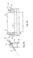
- the reference numeral 20 refers to the substructure of the rails 21 of two mutually adjoining tracks.
- the substructure 20 comprises an earthwork and, on top of this, a ballast bed in which sleepers are placed with the rails 21 mounted thereon.
- an overhead wire gantry 23 can further be recognized, having vertical columns 24 erected on both sides of the tracks.
- the columns 24 each stand on a heavy concrete foundation block 25.
- each block 25 two ground anchors 27 are driven obliquely into the earthwork beneath the ballast bed, after which the two ground anchors 27 are fixed by a fastening structure to the block 25 in a manner to be explained in greater detail.
- the anchors 27 lie at an angle of approximately 30° to the horizontal.
- the ground anchors 27 are of such a length that the ground anchors 27 of the mutually opposing blocks 25 cross and even run on to beneath the track beside the other block 25.
- a transverse girder 28 can be recognized, which is fixed by suitable bolts to the concrete block 25.
- the transverse girder 28 juts out of the block 25 at both ends and is provided at each end with a ground anchor support 29.
- the support 29 comprises a supporting plate 30 provided with a hole for the ground anchor 27.
- the relevant end of the ground anchor 27 is provided with screw thread and with a nut 31 screwed thereon. Tightening of the nut 31 brings it up against the supporting plate 30 and the ground anchor 27 is able to be tensioned.
- ground anchors 27 are in this example screw injection anchors 27, an injection of grout having taken place over the length L-grout.
- inventive concept is also applicable to gantries in which the foundation block is unitary with the column, for example where the column is made of concrete and the block is cast on.
Landscapes
- Engineering & Computer Science (AREA)
- Civil Engineering (AREA)
- Structural Engineering (AREA)
- Life Sciences & Earth Sciences (AREA)
- General Life Sciences & Earth Sciences (AREA)
- Mining & Mineral Resources (AREA)
- Paleontology (AREA)
- General Engineering & Computer Science (AREA)
- Architecture (AREA)
- Foundations (AREA)
- Railway Tracks (AREA)
Applications Claiming Priority (2)
| Application Number | Priority Date | Filing Date | Title |
|---|---|---|---|
| NL1016588 | 2000-11-13 | ||
| NL1016588A NL1016588C1 (nl) | 2000-11-13 | 2000-11-13 | Werkwijze voor het stabiliseren van de funderingsblokken van een bovenleidingsportaal in de onderbouw van een spoorbaan. |
Publications (2)
| Publication Number | Publication Date |
|---|---|
| EP1205605A2 true EP1205605A2 (de) | 2002-05-15 |
| EP1205605A3 EP1205605A3 (de) | 2003-05-07 |
Family
ID=19772374
Family Applications (1)
| Application Number | Title | Priority Date | Filing Date |
|---|---|---|---|
| EP01204318A Withdrawn EP1205605A3 (de) | 2000-11-13 | 2001-11-13 | Methode für das Stabilisieren eines Portalfundamentblocks von einer Eisenbahn |
Country Status (2)
| Country | Link |
|---|---|
| EP (1) | EP1205605A3 (de) |
| NL (1) | NL1016588C1 (de) |
Cited By (5)
| Publication number | Priority date | Publication date | Assignee | Title |
|---|---|---|---|---|
| FR2881448A1 (fr) * | 2005-01-31 | 2006-08-04 | Spie Fond S Sa | Procede de renforcement de fondations de pylone par jumelage |
| FR2970486A1 (fr) * | 2011-01-13 | 2012-07-20 | Soletanche Freyssinet | Procede de renforcement des fondations d'un pylone |
| ITMI20121160A1 (it) * | 2012-07-02 | 2014-01-03 | Mts S R L | Struttura di vincolo perfezionata e relativo procedimento di fissaggio per picchetti o paletti sul ballast di linee ferroviarie. |
| US11788246B2 (en) | 2020-12-14 | 2023-10-17 | Dale Clayton Miller | Micropile connection for supporting a vertical pile |
| US11828038B2 (en) | 2020-07-10 | 2023-11-28 | Dale Clayton Miller | Pile connection for horizontally fixing an elongated beam for a foundation support system |
Families Citing this family (2)
| Publication number | Priority date | Publication date | Assignee | Title |
|---|---|---|---|---|
| NL2018332B1 (nl) * | 2016-02-08 | 2018-01-11 | Volkerrail Nederland Bv | Werkwijze van plaatsen van een spoorweg portaalfundatieblok. |
| CN112499467A (zh) * | 2020-11-24 | 2021-03-16 | 中建八局轨道交通建设有限公司 | 地铁车站扩大端装配式龙门吊轨道基础及其施工方法 |
Family Cites Families (5)
| Publication number | Priority date | Publication date | Assignee | Title |
|---|---|---|---|---|
| US1896810A (en) * | 1929-04-24 | 1933-02-07 | Coyne Andre | Reenforced and anchored masonry structure |
| US4068445A (en) * | 1975-02-18 | 1978-01-17 | A. B. Chance Company | Lightweight, screw anchor supported foundation and method of installing same |
| US5395184A (en) * | 1993-01-29 | 1995-03-07 | Gagliano; Richard J. | Structure load transfer systems |
| DE19622119A1 (de) * | 1996-06-01 | 1997-12-04 | Rolf Hoericht | Windkraftanlage zur Erzeugung elektrischer Energie |
| FI2894U1 (fi) * | 1997-01-17 | 1997-05-20 | Jyrki Tarkkonen Oy | Putkiperustus |
-
2000
- 2000-11-13 NL NL1016588A patent/NL1016588C1/nl not_active IP Right Cessation
-
2001
- 2001-11-13 EP EP01204318A patent/EP1205605A3/de not_active Withdrawn
Cited By (5)
| Publication number | Priority date | Publication date | Assignee | Title |
|---|---|---|---|---|
| FR2881448A1 (fr) * | 2005-01-31 | 2006-08-04 | Spie Fond S Sa | Procede de renforcement de fondations de pylone par jumelage |
| FR2970486A1 (fr) * | 2011-01-13 | 2012-07-20 | Soletanche Freyssinet | Procede de renforcement des fondations d'un pylone |
| ITMI20121160A1 (it) * | 2012-07-02 | 2014-01-03 | Mts S R L | Struttura di vincolo perfezionata e relativo procedimento di fissaggio per picchetti o paletti sul ballast di linee ferroviarie. |
| US11828038B2 (en) | 2020-07-10 | 2023-11-28 | Dale Clayton Miller | Pile connection for horizontally fixing an elongated beam for a foundation support system |
| US11788246B2 (en) | 2020-12-14 | 2023-10-17 | Dale Clayton Miller | Micropile connection for supporting a vertical pile |
Also Published As
| Publication number | Publication date |
|---|---|
| NL1016588C1 (nl) | 2002-05-14 |
| EP1205605A3 (de) | 2003-05-07 |
Similar Documents
| Publication | Publication Date | Title |
|---|---|---|
| US5653388A (en) | Method and apparatus for constructing a permanent railroad track | |
| US20010046415A1 (en) | Concrete foundation pierhead and method of lifting a foundation using a jack assembly | |
| US20100175205A1 (en) | Scaffold Arrangement and Method for Repairing the Edge Structure of a Concrete Bridge | |
| JP5477898B2 (ja) | 直上高架橋の基礎工用施工装置及び施工方法 | |
| KR20190034815A (ko) | 기존 철도선로와 철도운행을 유지하는 철도교량 시공방법 | |
| CN208594436U (zh) | 一种抗隆起高速铁路岩石路堑结构 | |
| KR101260947B1 (ko) | 궤도지지 장치 | |
| CN213978389U (zh) | 一种齿轨铁路的轨道防爬设备 | |
| EP3049571B1 (de) | System und verfahren zur stabilisierung von schienenspurstrukturen mittels einer lastübertragungsvorrichtung | |
| EP1700954A2 (de) | Vorgefertigtes modulares Element, dieses Element einschließendes permanentes Tramwaygleis und unterirdisches Gleis, und Verfahren zu deren Auflegen | |
| CN211171643U (zh) | 墩顶挂架 | |
| NL1016588C1 (nl) | Werkwijze voor het stabiliseren van de funderingsblokken van een bovenleidingsportaal in de onderbouw van een spoorbaan. | |
| CN109594581B (zh) | 跨河段管道结构及其安装方法 | |
| CA2637208A1 (en) | Method for producing a ballastless track | |
| KR100571770B1 (ko) | 궤도지지 장치 | |
| DE19849266C2 (de) | Feste Fahrbahn für eine Straßenbahn | |
| JP4915214B2 (ja) | 盛土における基礎構造及び基礎の構築方法 | |
| HU210631B (en) | Railway body | |
| US2844325A (en) | Railway track construction | |
| RU2352705C1 (ru) | Способ укладки верхнего строения пути | |
| JP3926026B2 (ja) | アンカー固定式軌道構造及びアンカー固定式まくら木 | |
| JP2958875B1 (ja) | 軌道直下の切替工法 | |
| JP3396051B2 (ja) | 簡易軌框防護桁装置 | |
| US3920182A (en) | Heavy duty rail track assemblies | |
| CN212582304U (zh) | 一种新型铁路无渣轨道u型螺栓预埋工具 |
Legal Events
| Date | Code | Title | Description |
|---|---|---|---|
| PUAI | Public reference made under article 153(3) epc to a published international application that has entered the european phase |
Free format text: ORIGINAL CODE: 0009012 |
|
| AK | Designated contracting states |
Kind code of ref document: A2 Designated state(s): AT BE CH CY DE DK ES FI FR GB GR IE IT LI LU MC NL PT SE TR |
|
| AX | Request for extension of the european patent |
Free format text: AL;LT;LV;MK;RO;SI |
|
| PUAL | Search report despatched |
Free format text: ORIGINAL CODE: 0009013 |
|
| AK | Designated contracting states |
Designated state(s): AT BE CH CY DE DK ES FI FR GB GR IE IT LI LU MC NL PT SE TR |
|
| AX | Request for extension of the european patent |
Extension state: AL LT LV MK RO SI |
|
| 17P | Request for examination filed |
Effective date: 20031106 |
|
| AKX | Designation fees paid |
Designated state(s): AT BE CH CY DE DK ES FI FR GB GR IE IT LI LU MC NL PT SE TR |
|
| 17Q | First examination report despatched |
Effective date: 20040212 |
|
| STAA | Information on the status of an ep patent application or granted ep patent |
Free format text: STATUS: THE APPLICATION IS DEEMED TO BE WITHDRAWN |
|
| 18D | Application deemed to be withdrawn |
Effective date: 20061031 |