EP1205632A2 - Verfahren zum Lokalisieren eines Zementierstopfens im Bohrloch - Google Patents
Verfahren zum Lokalisieren eines Zementierstopfens im Bohrloch Download PDFInfo
- Publication number
- EP1205632A2 EP1205632A2 EP01309377A EP01309377A EP1205632A2 EP 1205632 A2 EP1205632 A2 EP 1205632A2 EP 01309377 A EP01309377 A EP 01309377A EP 01309377 A EP01309377 A EP 01309377A EP 1205632 A2 EP1205632 A2 EP 1205632A2
- Authority
- EP
- European Patent Office
- Prior art keywords
- plug
- fluid
- pressure pulse
- casing string
- displacement
- Prior art date
- Legal status (The legal status is an assumption and is not a legal conclusion. Google has not performed a legal analysis and makes no representation as to the accuracy of the status listed.)
- Withdrawn
Links
Images

Classifications
-
- E—FIXED CONSTRUCTIONS
- E21—EARTH OR ROCK DRILLING; MINING
- E21B—EARTH OR ROCK DRILLING; OBTAINING OIL, GAS, WATER, SOLUBLE OR MELTABLE MATERIALS OR A SLURRY OF MINERALS FROM WELLS
- E21B33/00—Sealing or packing boreholes or wells
- E21B33/10—Sealing or packing boreholes or wells in the borehole
- E21B33/13—Methods or devices for cementing, for plugging holes, crevices or the like
- E21B33/14—Methods or devices for cementing, for plugging holes, crevices or the like for cementing casings into boreholes
- E21B33/16—Methods or devices for cementing, for plugging holes, crevices or the like for cementing casings into boreholes using plugs for isolating cement charge; Plugs therefor
-
- E—FIXED CONSTRUCTIONS
- E21—EARTH OR ROCK DRILLING; MINING
- E21B—EARTH OR ROCK DRILLING; OBTAINING OIL, GAS, WATER, SOLUBLE OR MELTABLE MATERIALS OR A SLURRY OF MINERALS FROM WELLS
- E21B47/00—Survey of boreholes or wells
- E21B47/09—Locating or determining the position of objects in boreholes or wells, e.g. the position of an extending arm; Identifying the free or blocked portions of pipes
- E21B47/095—Locating or determining the position of objects in boreholes or wells, e.g. the position of an extending arm; Identifying the free or blocked portions of pipes by detecting an acoustic anomalies, e.g. using mud-pressure pulses
Definitions
- the present invention relates generally to operations performed in conjunction with a subterranean well and, in an embodiment described herein, more particularly provides a method of locating a cementing plug.
- top plug to separate cement pumped into a casing string from fluid used to displace the cement through the casing string.
- the fluid used to displace the plug, and thereby displace the cement, through the casing string is typically water, brine or mud.
- a predetermined volume of the displacement fluid is pumped into the casing string on top of the plug.
- the volume of the displacement fluid pumped into the casing string on top of the plug is usually equal to the internal volume of the casing string. In this manner, the plug is pumped to the bottom end of the casing string, and the cement formerly in the casing string is displaced into an annulus formed between the casing string and the wellbore.
- the plug lands in the float shoe at the same time as the predetermined volume of displacement fluid has been pumped into the casing string.
- the plug may be released into the casing string late, that is, after the displacement fluid has already begun to be pumped into the casing string. In this situation, it would be preferred to stop pumping the displacement fluid before the plug lands in the float shoe, so that the displacement fluid introduced into the casing string before the plug was released will not be displaced into the annulus.
- the exact volume of displacement fluid pumped into the casing string may not be known, thereby making it difficult to know how far the plug has been displaced through the casing string.
- a method which utilizes pressure pulses transmitted during a cementing operation to determine a location and displacement of a plug in a casing string.
- one or more pressure pulses are applied to the displacement fluid as it is being pumped into the casing string on top of the plug. If the speed of the pulse through the displacement fluid is known, then a difference in time between pulses reflected off of the plug will relate to a displacement speed of the plug. This information may be used to determine whether the plug is displacing in response to the displacement fluid being pumped into the casing string.
- one or more pressure pulses reflected off of the plug may be used to accurately determine the location of the plug in the casing string, or to estimate the location.
- a pressure pulse is transmitted through the displacement fluid a known distance, and the speed of the pressure pulse through the displacement fluid is determined before the displacement fluid is used to pump the plug through the casing string.
- the speed of the pressure pulse through the fluid will be accurately known for use in calculating the location of the plug.
- an approximate speed of the pressure pulse through the displacement fluid may be used.
- the location of the plug may be estimated by transmitting a pressure pulse through the fluid in the casing string and counting reflections of the pressure pulse due to known anomalies in the casing string. For example, pressure pulse reflections due to collars in the casing string may be received prior to receiving a reflection due to the plug. By counting the number of the collar reflections prior to the plug reflection, the location of the plug in the casing string may be estimated within the length of one joint of casing.
- a method of determining displacement of a device through a tubular string positioned in a well comprising the steps of: pumping a fluid into the tubular string; displacing the device through the tubular string in response to the pumping step; transmitting at least one pressure pulse through the fluid; reflecting the pressure pulse off of the device; and receiving the reflected pressure pulse.
- the transmitting, reflecting and receiving steps are performed during the pumping step.
- multiple pressure pulses are transmitted through the fluid, reflected off of the device and received.
- the method further comprises the step of calculating a displacement of the device based on a time difference between received reflected pressure pulses.
- the calculating step may further comprise calculating the displacement further based on a known speed of the pressure pulses through the fluid.
- the method may further comprise the step of transmitting a pulse through the fluid a known distance to thereby determine the known speed of the pressure pulses in the calculating step.
- the device is a cementing plug separating the fluid from cement in the tubular string.
- the receiving step further comprises receiving the transmitted pressure pulse
- the method further comprises the step of determining a time difference between the transmitted pressure pulse and the reflected pressure pulse.
- the method may further comprise the step of calculating a position of the device based on the time difference between the transmitted pressure pulse and the reflected pressure pulse.
- the calculating step may further comprise calculating the position of the device based on a speed of the pressure pulses through the fluid.
- the method may further comprise the step of determining the speed of the pressure pulses through the fluid by transmitting a pulse through the fluid a known distance prior to the pumping step.
- a method of determining a location of a device in a tubular string comprising the steps of: pumping a fluid into the tubular string on top of the device, thereby displacing the device through the tubular string; and reflecting at least one pressure pulse off of the device through the fluid.
- the method further comprises the steps of transmitting the pressure pulse through the fluid and receiving the reflected pressure pulse.
- the method may further comprise the step of recording a time difference between the transmitting and receiving steps.
- the method may further comprise the step of determining the location of the device based on the time difference and a speed of the pressure pulse through the fluid.
- the method may further comprise the step of determining the speed of the pressure pulse through the fluid by transmitting a pulse through the fluid a known distance prior to the pumping step.
- a method of locating a cementing plug in a subterranean well comprising the steps of: pumping cement into a casing string; releasing a plug into the casing string; displacing the plug and cement through the casing string by pumping a fluid into the casing string on top of the plug; and reflecting at least one pressure pulse off of the plug through the fluid during the displacing step.
- the reflecting step multiple pressure pulses are reflected off of the plug during the displacing step.
- the method may further comprise the step of determining a displacement of the plug based on a time difference between the pressure pulses being reflected off of the plug.
- the method may further comprise the step of determining a location of the plug based on a time difference between transmitting and receiving the pulse reflected off of the plug.
- the method further comprises the step of transmitting a pulse through the fluid in the casing string a known distance prior to the pumping step.
- the method may further comprise the step of determining a speed of the pulse through the fluid based on a time the pulse travels the known distance through the fluid in the casing string.
- a method of determining displacement of a device through a tubular string positioned in a well comprising the steps of: reflecting at least one pressure pulse off of the device while the device is displacing through the tubular string; and receiving the reflected pressure pulse.
- the method further comprises the steps of pumping a fluid into the tubular string and transmitting the pressure pulse through the fluid.
- multiple pressure pulses are reflected off of the device.
- the method may further comprise the step of calculating a displacement of the device based on a time difference between receiving the respective multiple reflected pressure pulses.
- the calculating step may further comprise calculating the displacement further based on a known speed of the pressure pulses through a fluid in the tubular string.
- the method may further comprise the step of transmitting a pulse through the fluid a known distance to thereby determine the known speed of the pressure pulses in the calculating step.
- the device is a cementing plug separating a fluid from cement in the tubular string.
- the receiving step further comprises receiving the pressure pulse as the pressure pulse is transmitted, and further comprising the step of determining a time difference between the received transmitted pressure pulse and the received reflected pressure pulse.
- the method may further comprise the step of calculating a position of the device based on the time difference between the received transmitted pressure pulse and the received reflected pressure pulse.
- the calculating step may further comprise calculating the position of the device based on a speed of the pressure pulses through fluid in the tubular string.
- the method may further comprise the step of determining the speed of the pressure pulses through the fluid by transmitting a pulse through the fluid a known distance.
- the reflecting step further comprises reflecting the pressure pulse off of at least one anomaly in the well other than the device, and wherein the receiving step further comprises receiving the pressure pulse reflected off of the anomaly.
- the method may further comprise the step of determining the displacement of the device in the well by relating the pressure pulse as reflected off of the device to the pressure pulse as reflected off of the anomaly.
- the pressure pulse is reflected off of multiple anomalies in the well, and further comprising the step of determining the displacement of the device in the well by counting a number reflections of the pressure pulse off of the anomalies received prior to receiving the reflection of the pressure pulse off of the device.
- the determining step further comprises multiplying the number of anomaly reflections by an average spacing between the anomalies in the well.
- the determining step further comprises summing anomaly spacings corresponding to the anomalies for which the number of anomaly reflections were counted in the counting step.
- a method of determining a location of a device in a well comprising the steps of: transmitting at least one pressure pulse in the well; reflecting the pressure pulse off of the device and off of at least one anomaly other than the device, wherein a position of the anomaly in the well is known; receiving the device reflection and the anomaly reflection; and determining the location of the device based on the known position of the anomaly and a relationship between the device and anomaly reflections.
- the reflecting step multiple anomalies are positioned in the well, in the receiving step multiple anomaly reflections are received, and in the determining step the location of the device is based in part on the relationship between the device reflection and the multiple anomaly reflections.
- spacings between each of the anomalies in the well may be known.
- the determining step may further comprise determining the location of the device in the well by counting a number reflections of the pressure pulse off of the anomalies received prior to receiving the reflection of the pressure pulse off of the device.
- the determining step further comprises multiplying the number of anomaly reflections by an average spacing between the anomalies in the well.
- the determining step further comprises summing anomaly spacings corresponding to the anomalies for which the number of anomaly reflections were counted in the counting step.
- the device is a cementing plug and there are multiple anomalies positioned in the well, the anomalies being casing collars, and the determining step may further comprise determining the location of the plug in the well by counting a number reflections of the pressure pulse off of the casing collars received prior to receiving the reflection of the pressure pulse off of the plug.
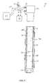
- FIG. 1 Representatively illustrated in FIG. 1 is a method 10 which embodies principles of the present invention.
- directional terms such as “above”, “below”, “upper”, “lower”, etc., are used only for convenience in referring to the accompanying drawings. Additionally, it is to be understood that the various embodiments of the present invention described herein may be utilized in various orientations, such as inclined, inverted, horizontal, vertical, etc., and in various configurations, without departing from the principles of the present invention.
- the method 10 utilizes pressure pulses to determine the location and/or displacement of a cementing plug in a casing string 12 positioned in a wellbore 14.
- the use of pressure pulses for determining the length of a fluid conduit in a wellbore is described in U.S. Patent No. 5,754,495. Methods of transmitting and receiving pressure pulses through fluid conduits described in that patent are not repeated herein.
- the length of the casing string 12 is known, and so a different problem is presented as compared to that resolved in U.S. Patent No. 5,754,495.
- a cementing operation is to be performed in the method 10, wherein a cementing plug is released into the casing string 12, and the problem is how to determine the plug's location in, and/or displacement through, the casing string.
- principles of the present invention may be successfully applied in other methods wherein a device is displaced through a tubular string.
- a conventional plug release head 16 is connected at an upper end of the casing string 12.
- the release head 16 is used to release the plug into the casing string 12 at an appropriate point in the cementing operation.
- Valves 18 are connected between the release head 16 and a pump 20.
- the pump 20 is used to pump cement and displacement fluid (such as water, mud, brine, etc.) through the casing string 12.
- Another valve 22 is interconnected to a flowline 24 extending between the pump 20 and the valves 18.
- the valve 22 is used to transmit pressure pulses via the flowline 24 to the fluid in the casing string 12. Specifically, the valve 22 is opened momentarily to vent pressure from the flowline 24 and, thus, transmit a negative pressure pulse through the fluid in the casing string 12.
- a device known to those skilled in the art as an air gun may be used to transmit a positive pressure pulse through the fluid in the casing string 12.
- the pump 20 may be operated in such a manner as to transmit a pressure pulse, such as by varying the pump's motor speed or by momentarily disengaging the motor from the pump, etc.
- a pressure transducer 26 is connected to the flowline 24.
- the transducer 26 is used to determine the timing of various events related to transmission of pressure pulses and reflection of those pressure pulses. For example, in the method 10 as depicted in FIG. 1, a pressure pulse may be transmitted through the fluid 34 (typically water, mud or brine) in the casing string 12 prior to cement being pumped into the casing, and reflected off of a float shoe 28 back through the fluid to the flowline 24.
- the fluid 34 typically water, mud or brine
- the difference in time between the pressure pulse transmission (as detected at the transducer) and the pressure pulse being reflected back to the transducer may be readily measured, the speed (distance/time) of the pressure pulse through the fluid 34 may be accurately determined. Note that this information may be very useful later in the method 10 for accurately determining the cementing plug's location and/or displacement through the casing string 12.
- a controller 30 or other computing device is used to actuate the valve 22 and to record the output of the transducer 26.
- the controller 30 may also be used for other functions, such as computing time differences, speeds and locations, and for relating these to various events in the cementing operation, such as the time of release of the cementing plug, etc. For example, if the controller 30 determines that the plug was released late, that is, that a volume of displacement fluid was pumped into the casing string 12 prior to the plug being released, then a calculation may be made as to when pumping of the displacement fluid should cease so that the displacement fluid below the plug is not forced into an annulus 32 between the casing string and the wellbore 14.
- the method 10 is depicted wherein cement 36 has been pumped into the casing string 12.
- a plug may be used to separate the cement from the fluid.
- This plug is not shown or described herein, but it is to be understood that the principles of the present invention may be used to determine this plug's location and/or displacement, as well as that of the plug as described below.
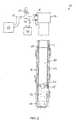
- the method 10 is depicted wherein a plug 42 has been released from the release head 16 into the casing string 12 on top of the cement 36.
- the release of the plug 42 is accomplished by withdrawing a pin (not shown) in the release head 16 and manipulating the valves 18 to direct fluid on top of the plug and thereby push the plug out of the release head into the casing string 12.
- a displacement fluid 40 is pumped by the pump 20 on top of the plug 42.
- the displacement fluid 40 is generally the same as the fluid 34 in the casing string 12 prior to the cement 36 being pumped into the casing string.
- the pressure pulse speed through the fluid 34 determined as described above is generally also the speed of a pressure pulse through the displacement fluid 40.
- the plug 42 serves to separate the cement 36 from the displacement fluid 40, to force the cement through the shoe 28 and into the annulus 32, and to land in the shoe (or collar) and thereby provide an indication that all of the cement has been displaced out of the casing string 12.
- the location or position of the plug 42 may be readily determined in the method 10 by transmitting a pressure pulse through the displacement fluid 40 (e.g., by momentarily opening the valve 22). The pressure pulse will reflect off of the plug 42 and back to the transducer 26.
- the location of the plug 42 can be readily computed (speed x time) at any point after the plug has been released.
- the displacement speed of the plug may be readily determined by dividing respective changes in distance by differences in time.
- an operator may be informed whether the plug 42 is appropriately displacing through the casing string 12 for the rate of displacement fluid being pumped. A slower than expected speed of the plug 42 might indicate that displacement fluid is leaking past the plug.
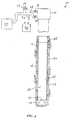
- the method 10 is depicted wherein the plug 42 has landed in the shoe 28 (or in a float collar associated with the shoe). It is usually expected that a pressure increase will accompany any further pumping of displacement fluid 40 into the casing string 12 after the plug 42 has landed in the shoe 28.
- the location of the plug 42 When such a pressure increase is detected, it may be desirable to determine the location of the plug 42, so that it may be known whether the plug has indeed landed in the shoe 28 (or collar), or has encountered some other obstruction in the casing string 12.
- the position of the plug 42 in the casing string 12 may be readily confirmed by transmitting a pressure pulse through the fluid 40, reflecting the pressure pulse off of the plug 42 and back to the transducer 26. The difference in time between transmitting the pressure pulse and receiving the reflected pressure pulse may then be used to compute the location of the plug 42.
- a prior determination of the location of the plug 42 has indicated that the plug was released late, that is, after a volume of displacement fluid 40 was pumped into the casing string 12, it may be desired to stop pumping the displacement fluid prior to the plug 42 landing in the shoe 28 (or collar).
- the location of the plug 42 may be confirmed as described above, and as often as desired, to ensure that the plug is positioned properly in the casing string 12 when pumping of the displacement fluid 40 is ceased.
- pressure pulse speed through the fluid 40 it is not necessary for the pressure pulse speed through the fluid 40 to be precisely known for the information received in the method 10 to be useful. For example, even if the pressure pulse speed is not known, displacement of the plug 42 through the casing string 12 may still be confirmed during pumping of the displacement fluid 40 by observing a succession of increased times for pulses to be reflected back to the transducer 26. A lack of an increase in times for successive reflected pulses would be an indication that the plug 42 has ceased displacing through the casing string 12. Furthermore, approximate pressure pulse speeds for various fluids (e.g., water, mud, brine, etc.) may be used to approximate a location for the plug 42 based on the time measured for a pulse to be reflected off of the plug.
- fluids e.g., water, mud, brine, etc.
- the casing string 12 includes casing collars 44 interconnected at known intervals between individual joints of casing. Each of these collars 44 will reflect the pressure pulses back to the pressure transducer 26, although these reflections will be quite small in amplitude. By counting the number of these casing collar reflections that are received prior to receiving the pressure pulse reflected off of the plug 42, the number of casing collars 44 above the plug may be determined.
- the depth of the plug 42 in the casing string 12 may be readily determined, for example, by multiplying the number of casing collars by the average casing joint length, or by summing the individual lengths of the corresponding casing joints. This method provides an estimate of the depth of the plug 42 in the casing string 12 accurate to within the length of one joint of casing.
Landscapes
- Physics & Mathematics (AREA)
- Mining & Mineral Resources (AREA)
- Geology (AREA)
- Life Sciences & Earth Sciences (AREA)
- Engineering & Computer Science (AREA)
- Fluid Mechanics (AREA)
- Environmental & Geological Engineering (AREA)
- General Life Sciences & Earth Sciences (AREA)
- Geochemistry & Mineralogy (AREA)
- Geophysics (AREA)
- Acoustics & Sound (AREA)
- Reciprocating Pumps (AREA)
- Measuring Fluid Pressure (AREA)
- Earth Drilling (AREA)
- Investigating Strength Of Materials By Application Of Mechanical Stress (AREA)
Applications Claiming Priority (2)
| Application Number | Priority Date | Filing Date | Title |
|---|---|---|---|
| US711665 | 2000-11-09 | ||
| US09/711,665 US6401814B1 (en) | 2000-11-09 | 2000-11-09 | Method of locating a cementing plug in a subterranean wall |
Publications (2)
| Publication Number | Publication Date |
|---|---|
| EP1205632A2 true EP1205632A2 (de) | 2002-05-15 |
| EP1205632A3 EP1205632A3 (de) | 2003-03-12 |
Family
ID=24859012
Family Applications (1)
| Application Number | Title | Priority Date | Filing Date |
|---|---|---|---|
| EP01309377A Withdrawn EP1205632A3 (de) | 2000-11-09 | 2001-11-06 | Verfahren zum Lokalisieren eines Zementierstopfens im Bohrloch |
Country Status (5)
| Country | Link |
|---|---|
| US (1) | US6401814B1 (de) |
| EP (1) | EP1205632A3 (de) |
| AU (1) | AU767111B2 (de) |
| CA (1) | CA2362041C (de) |
| NO (1) | NO20015423L (de) |
Cited By (1)
| Publication number | Priority date | Publication date | Assignee | Title |
|---|---|---|---|---|
| WO2006000742A1 (en) * | 2004-06-28 | 2006-01-05 | Halliburton Energy Services, Inc. | System and method for monitoring and removing blockage in a downhole oil and gas recovery operation |
Families Citing this family (33)
| Publication number | Priority date | Publication date | Assignee | Title |
|---|---|---|---|---|
| US6789619B2 (en) | 2002-04-10 | 2004-09-14 | Bj Services Company | Apparatus and method for detecting the launch of a device in oilfield applications |
| US6802373B2 (en) * | 2002-04-10 | 2004-10-12 | Bj Services Company | Apparatus and method of detecting interfaces between well fluids |
| US7219730B2 (en) | 2002-09-27 | 2007-05-22 | Weatherford/Lamb, Inc. | Smart cementing systems |
| US7252152B2 (en) | 2003-06-18 | 2007-08-07 | Weatherford/Lamb, Inc. | Methods and apparatus for actuating a downhole tool |
| US6874361B1 (en) * | 2004-01-08 | 2005-04-05 | Halliburton Energy Services, Inc. | Distributed flow properties wellbore measurement system |
| US20050241538A1 (en) * | 2004-04-28 | 2005-11-03 | Vargo Richard F Jr | Methods of making cement compositions using liquid additives containing lightweight beads |
| US20050241545A1 (en) * | 2004-04-28 | 2005-11-03 | Vargo Richard F Jr | Methods of extending the shelf life of and revitalizing lightweight beads for use in cement compositions |
| US7527109B2 (en) * | 2004-11-01 | 2009-05-05 | Doyle & Wachstetter, Inc. | Locating apparatus and system |
| US7373981B2 (en) | 2005-02-14 | 2008-05-20 | Halliburton Energy Services, Inc. | Methods of cementing with lightweight cement compositions |
| US7390356B2 (en) * | 2005-03-11 | 2008-06-24 | Halliburton Energy Services, Inc. | Compositions for high temperature lightweight cementing |
| US7398827B2 (en) * | 2005-03-11 | 2008-07-15 | Halliburton Energy Services, Inc. | Methods for high temperature lightweight cementing |
| CA2513166A1 (en) * | 2005-06-30 | 2006-12-30 | Javed Shah | Method of monitoring gas influx into a well bore when drilling an oil and gas well, and apparatus constructed in accordance with the method |
| CA2512437C (en) * | 2005-07-04 | 2013-09-03 | Javed Shah | Method of controlling a well |
| EP1830035A1 (de) * | 2006-03-01 | 2007-09-05 | Shell Internationale Researchmaatschappij B.V. | Verfahren zur Positionsdetektion von bewegten Objekten im Bohrloch |
| CN101294489B (zh) * | 2007-04-23 | 2012-05-30 | 中国石油化工股份有限公司河南油田分公司石油工程技术研究院 | 一种井下管柱受力及位移检测装置 |
| US20100051264A1 (en) * | 2008-08-29 | 2010-03-04 | Baker Hughes Incorporated | Method and system for monitoring downhole completion operations |
| US9453404B2 (en) | 2010-01-29 | 2016-09-27 | Schlumberger Technology Corporation | Mechanical tube wave sources and methods of use for liquid filled boreholes |
| US9841523B2 (en) * | 2010-01-29 | 2017-12-12 | Schlumberger Technology Corporation | Tube wave generation |
| US10550836B2 (en) | 2010-07-26 | 2020-02-04 | Schlumberger Technology Corproation | Frequency sweeping tubewave sources for liquid filled boreholes |
| US9249646B2 (en) * | 2011-11-16 | 2016-02-02 | Weatherford Technology Holdings, Llc | Managed pressure cementing |
| WO2016108906A1 (en) * | 2014-12-31 | 2016-07-07 | Halliburton Energy Services, Inc. | Pulse reflection travel time analysis to track position of a downhole object |
| US10590758B2 (en) | 2015-11-12 | 2020-03-17 | Schlumberger Technology Corporation | Noise reduction for tubewave measurements |
| WO2017188992A1 (en) | 2016-04-29 | 2017-11-02 | Halliburton Energy Services, Inc. | Restriction system for tracking downhole devices with unique pressure signals |
| WO2018004369A1 (ru) | 2016-07-01 | 2018-01-04 | Шлюмберже Канада Лимитед | Способ и система для обнаружения в скважине объектов, отражающих гидравлический сигнал |
| US12060786B2 (en) | 2018-02-08 | 2024-08-13 | Halliburton Energy Services, Inc. | Wellbore inspection system |
| US11572759B2 (en) * | 2019-08-02 | 2023-02-07 | Halliburton Energy Services, Inc. | Distributed acoustic sensor with trackable plug |
| CN114341462A (zh) | 2019-08-28 | 2022-04-12 | 斯伦贝谢技术有限公司 | 用于确定在井筒中的可下放物体的位置的方法 |
| MX2023001197A (es) * | 2020-07-30 | 2023-03-14 | Schlumberger Technology Bv | Métodos para determinar una posición de un objeto introducible en un pozo. |
| WO2022060391A1 (en) | 2020-09-18 | 2022-03-24 | Halliburton Energy Services, Inc. | Non-intrusive tracking of objects in pipelines and wellbores |
| EP4515077A4 (de) * | 2022-04-28 | 2026-03-04 | Services Petroliers Schlumberger | Verfahren zur bestimmung einer position eines zerlegbaren objekts in einem bohrloch |
| WO2025188302A1 (en) * | 2024-03-06 | 2025-09-12 | Halliburton Energy Services, Inc. | Data-driven methods to determine position of a moving object in a wellbore |
| US12590533B2 (en) | 2024-07-19 | 2026-03-31 | Schlumberger Technology Corporation | Droppable object with locating system and pressure pulse telemetry actuator for use in a wellbore |
| US12541024B1 (en) * | 2025-01-27 | 2026-02-03 | Halliburton Energy Services, Inc. | Remote detection of top of cement using energy pulses |
Family Cites Families (16)
| Publication number | Priority date | Publication date | Assignee | Title |
|---|---|---|---|---|
| US2999557A (en) * | 1956-05-28 | 1961-09-12 | Halliburton Co | Acoustic detecting and locating apparatus |
| US3265151A (en) * | 1962-06-15 | 1966-08-09 | Halliburton Co | Means and techniques useful in establishing quality of cement bonds in cased boreholes |
| US3637038A (en) * | 1970-07-24 | 1972-01-25 | Texaco Inc | Method for retrieving a lost tool in a borehole using an acoustical well sounder |
| US4093028A (en) * | 1973-10-12 | 1978-06-06 | Orpha B. Brandon | Methods of use of cementitious materials and sonic or energy-carrying waves within subsurface formations |
| US4548271A (en) * | 1983-10-07 | 1985-10-22 | Exxon Production Research Co. | Oscillatory flow method for improved well cementing |
| US4819726A (en) * | 1985-06-10 | 1989-04-11 | Amoco Corporation | Method for indicating the position of a cement wiper plug prior to its bottomhole arrival |
| US4907649A (en) * | 1987-05-15 | 1990-03-13 | Bode Robert E | Restriction subs for setting cement plugs in wells |
| US5377160A (en) * | 1993-08-05 | 1994-12-27 | Computalog Research, Inc. | Transmitter and receiver to radially scan the cementing conditions in cased wells |
| GB2290811A (en) * | 1994-05-25 | 1996-01-10 | Bp Exploration Operating | Cementing process and apparatus |
| US6125935A (en) * | 1996-03-28 | 2000-10-03 | Shell Oil Company | Method for monitoring well cementing operations |
| US5754495A (en) | 1996-05-13 | 1998-05-19 | Halliburton Energy Services, Inc. | Method for acoustic determination of the length of a fluid conduit |
| US5829523A (en) * | 1997-03-31 | 1998-11-03 | Halliburton Energy Services, Inc. | Primary well cementing methods and apparatus |
| US5950725A (en) * | 1997-09-30 | 1999-09-14 | Schlumberger Technology Corporation | Hydraulic wiper plug launcher |
| US5967231A (en) * | 1997-10-31 | 1999-10-19 | Halliburton Energy Services, Inc. | Plug release indication method |
| US6053245A (en) * | 1998-03-03 | 2000-04-25 | Gas Research Institute | Method for monitoring the setting of well cement |
| US6333699B1 (en) * | 1998-08-28 | 2001-12-25 | Marathon Oil Company | Method and apparatus for determining position in a pipe |
-
2000
- 2000-11-09 US US09/711,665 patent/US6401814B1/en not_active Expired - Fee Related
-
2001
- 2001-10-24 AU AU83598/01A patent/AU767111B2/en not_active Ceased
- 2001-11-06 NO NO20015423A patent/NO20015423L/no not_active Application Discontinuation
- 2001-11-06 EP EP01309377A patent/EP1205632A3/de not_active Withdrawn
- 2001-11-08 CA CA002362041A patent/CA2362041C/en not_active Expired - Fee Related
Cited By (2)
| Publication number | Priority date | Publication date | Assignee | Title |
|---|---|---|---|---|
| WO2006000742A1 (en) * | 2004-06-28 | 2006-01-05 | Halliburton Energy Services, Inc. | System and method for monitoring and removing blockage in a downhole oil and gas recovery operation |
| US7318471B2 (en) | 2004-06-28 | 2008-01-15 | Halliburton Energy Services, Inc. | System and method for monitoring and removing blockage in a downhole oil and gas recovery operation |
Also Published As
| Publication number | Publication date |
|---|---|
| CA2362041C (en) | 2009-03-03 |
| CA2362041A1 (en) | 2002-05-09 |
| US6401814B1 (en) | 2002-06-11 |
| EP1205632A3 (de) | 2003-03-12 |
| NO20015423L (no) | 2002-05-10 |
| AU8359801A (en) | 2002-05-16 |
| NO20015423D0 (no) | 2001-11-06 |
| AU767111B2 (en) | 2003-10-30 |
Similar Documents
| Publication | Publication Date | Title |
|---|---|---|
| US6401814B1 (en) | Method of locating a cementing plug in a subterranean wall | |
| US12534999B2 (en) | Methods for determining a position of a droppable object in a wellbore | |
| US9103203B2 (en) | Wireless logging of fluid filled boreholes | |
| NO20161857A1 (en) | Acoustic calipering and analysis of annulus materials | |
| US12234719B2 (en) | Methods for determining a position of a droppable object in a wellbore | |
| NO20161691A1 (en) | Locating a downhole tool in a wellbore | |
| US11719087B2 (en) | Modeling friction along a wellbore | |
| US20140096956A1 (en) | System and method of monitoring displacement of a member during a downhole completion operation | |
| US12584374B2 (en) | Methods for determining positions of fluid interfaces and detecting cement setting in a subterranean wellbore | |
| CN107605463A (zh) | 一种用于钻井堵漏施工的井筒动液面监测方法 | |
| AU2019460122B2 (en) | Distributed acoustic sensor with trackable plug | |
| NO316722B1 (no) | Anordning og fremgangsmate for lydhastighetskompensert akustisk maling av avstand mellom borestreng og borehullsvegg | |
| AU710013B2 (en) | Method for acoustic determination of the length of a fluid conduit | |
| EP1234101B1 (de) | Verfahren zur leckerkennung | |
| US20240035371A1 (en) | Methods for determining a position of a droppable object in a wellbore | |
| CN205172564U (zh) | 钻井液漏失位置测量装置 | |
| US20250347217A1 (en) | Methods for determining a position of a droppable object in a wellbore | |
| EA045646B1 (ru) | Способ определения положения сбрасываемого объекта в стволе скважины | |
| US12590533B2 (en) | Droppable object with locating system and pressure pulse telemetry actuator for use in a wellbore | |
| RU2805636C1 (ru) | Способ определения положения сбрасываемой цементировочной пробки в обсадной колонне | |
| EA044477B1 (ru) | Способ определения положения цементировочной пробки в стволе скважины |
Legal Events
| Date | Code | Title | Description |
|---|---|---|---|
| PUAI | Public reference made under article 153(3) epc to a published international application that has entered the european phase |
Free format text: ORIGINAL CODE: 0009012 |
|
| AK | Designated contracting states |
Kind code of ref document: A2 Designated state(s): AT BE CH CY DE DK ES FI FR GB GR IE IT LI LU MC NL PT SE TR |
|
| AX | Request for extension of the european patent |
Free format text: AL;LT;LV;MK;RO;SI |
|
| PUAL | Search report despatched |
Free format text: ORIGINAL CODE: 0009013 |
|
| AK | Designated contracting states |
Kind code of ref document: A3 Designated state(s): AT BE CH CY DE DK ES FI FR GB GR IE IT LI LU MC NL PT SE TR Designated state(s): AT BE CH CY DE DK ES FI FR GB GR IE IT LI LU MC NL PT SE TR |
|
| AX | Request for extension of the european patent |
Extension state: AL LT LV MK RO SI |
|
| 17P | Request for examination filed |
Effective date: 20030528 |
|
| 17Q | First examination report despatched |
Effective date: 20030804 |
|
| AKX | Designation fees paid |
Designated state(s): DE FR GB NL |
|
| STAA | Information on the status of an ep patent application or granted ep patent |
Free format text: STATUS: THE APPLICATION IS DEEMED TO BE WITHDRAWN |
|
| 18D | Application deemed to be withdrawn |
Effective date: 20031216 |