EP1205661A1 - Windmotor mit senkrechter Drehachse - Google Patents
Windmotor mit senkrechter Drehachse Download PDFInfo
- Publication number
- EP1205661A1 EP1205661A1 EP01305525A EP01305525A EP1205661A1 EP 1205661 A1 EP1205661 A1 EP 1205661A1 EP 01305525 A EP01305525 A EP 01305525A EP 01305525 A EP01305525 A EP 01305525A EP 1205661 A1 EP1205661 A1 EP 1205661A1
- Authority
- EP
- European Patent Office
- Prior art keywords
- blade
- prime mover
- arm
- shaft
- fluid
- Prior art date
- Legal status (The legal status is an assumption and is not a legal conclusion. Google has not performed a legal analysis and makes no representation as to the accuracy of the status listed.)
- Withdrawn
Links
- 239000012530 fluid Substances 0.000 claims abstract description 52
- 230000000694 effects Effects 0.000 claims abstract description 14
- MROJXXOCABQVEF-UHFFFAOYSA-N Actarit Chemical compound CC(=O)NC1=CC=C(CC(O)=O)C=C1 MROJXXOCABQVEF-UHFFFAOYSA-N 0.000 claims abstract 18
- 238000000034 method Methods 0.000 claims description 13
- XLYOFNOQVPJJNP-UHFFFAOYSA-N water Substances O XLYOFNOQVPJJNP-UHFFFAOYSA-N 0.000 claims description 7
- 230000014759 maintenance of location Effects 0.000 description 7
- 230000005611 electricity Effects 0.000 description 6
- 238000006073 displacement reaction Methods 0.000 description 4
- VNWKTOKETHGBQD-UHFFFAOYSA-N methane Chemical compound C VNWKTOKETHGBQD-UHFFFAOYSA-N 0.000 description 4
- 239000003245 coal Substances 0.000 description 3
- 239000003921 oil Substances 0.000 description 3
- 239000002901 radioactive waste Substances 0.000 description 3
- IJGRMHOSHXDMSA-UHFFFAOYSA-N Atomic nitrogen Chemical compound N#N IJGRMHOSHXDMSA-UHFFFAOYSA-N 0.000 description 2
- CURLTUGMZLYLDI-UHFFFAOYSA-N Carbon dioxide Chemical compound O=C=O CURLTUGMZLYLDI-UHFFFAOYSA-N 0.000 description 2
- 238000002485 combustion reaction Methods 0.000 description 2
- 230000000254 damaging effect Effects 0.000 description 2
- 239000007789 gas Substances 0.000 description 2
- 239000003345 natural gas Substances 0.000 description 2
- 230000002285 radioactive effect Effects 0.000 description 2
- 239000002699 waste material Substances 0.000 description 2
- NINIDFKCEFEMDL-UHFFFAOYSA-N Sulfur Chemical compound [S] NINIDFKCEFEMDL-UHFFFAOYSA-N 0.000 description 1
- 239000005864 Sulphur Substances 0.000 description 1
- 238000003916 acid precipitation Methods 0.000 description 1
- 238000003915 air pollution Methods 0.000 description 1
- 239000001569 carbon dioxide Substances 0.000 description 1
- 229910002092 carbon dioxide Inorganic materials 0.000 description 1
- 238000006243 chemical reaction Methods 0.000 description 1
- 230000007613 environmental effect Effects 0.000 description 1
- 239000003344 environmental pollutant Substances 0.000 description 1
- 230000004992 fission Effects 0.000 description 1
- 239000002803 fossil fuel Substances 0.000 description 1
- 238000007689 inspection Methods 0.000 description 1
- 230000002427 irreversible effect Effects 0.000 description 1
- 229910052757 nitrogen Inorganic materials 0.000 description 1
- 231100000719 pollutant Toxicity 0.000 description 1
- 230000005855 radiation Effects 0.000 description 1
- 239000012857 radioactive material Substances 0.000 description 1
- 230000000717 retained effect Effects 0.000 description 1
- 238000010792 warming Methods 0.000 description 1
Images





Classifications
-
- F—MECHANICAL ENGINEERING; LIGHTING; HEATING; WEAPONS; BLASTING
- F03—MACHINES OR ENGINES FOR LIQUIDS; WIND, SPRING, OR WEIGHT MOTORS; PRODUCING MECHANICAL POWER OR A REACTIVE PROPULSIVE THRUST, NOT OTHERWISE PROVIDED FOR
- F03D—WIND MOTORS
- F03D3/00—Wind motors with rotation axis substantially perpendicular to the air flow entering the rotor
- F03D3/06—Rotors
-
- F—MECHANICAL ENGINEERING; LIGHTING; HEATING; WEAPONS; BLASTING
- F03—MACHINES OR ENGINES FOR LIQUIDS; WIND, SPRING, OR WEIGHT MOTORS; PRODUCING MECHANICAL POWER OR A REACTIVE PROPULSIVE THRUST, NOT OTHERWISE PROVIDED FOR
- F03D—WIND MOTORS
- F03D3/00—Wind motors with rotation axis substantially perpendicular to the air flow entering the rotor
- F03D3/06—Rotors
- F03D3/062—Rotors characterised by their construction elements
- F03D3/066—Rotors characterised by their construction elements the wind engaging parts being movable relative to the rotor
- F03D3/067—Cyclic movements
-
- F—MECHANICAL ENGINEERING; LIGHTING; HEATING; WEAPONS; BLASTING
- F03—MACHINES OR ENGINES FOR LIQUIDS; WIND, SPRING, OR WEIGHT MOTORS; PRODUCING MECHANICAL POWER OR A REACTIVE PROPULSIVE THRUST, NOT OTHERWISE PROVIDED FOR
- F03B—MACHINES OR ENGINES FOR LIQUIDS
- F03B17/00—Other machines or engines
- F03B17/06—Other machines or engines using liquid flow with predominantly kinetic energy conversion, e.g. of swinging-flap type, "run-of-river", "ultra-low head"
- F03B17/062—Other machines or engines using liquid flow with predominantly kinetic energy conversion, e.g. of swinging-flap type, "run-of-river", "ultra-low head" with rotation axis substantially at right angle to flow direction
- F03B17/065—Other machines or engines using liquid flow with predominantly kinetic energy conversion, e.g. of swinging-flap type, "run-of-river", "ultra-low head" with rotation axis substantially at right angle to flow direction the flow engaging parts having a cyclic movement relative to the rotor during its rotation
-
- F—MECHANICAL ENGINEERING; LIGHTING; HEATING; WEAPONS; BLASTING
- F03—MACHINES OR ENGINES FOR LIQUIDS; WIND, SPRING, OR WEIGHT MOTORS; PRODUCING MECHANICAL POWER OR A REACTIVE PROPULSIVE THRUST, NOT OTHERWISE PROVIDED FOR
- F03D—WIND MOTORS
- F03D3/00—Wind motors with rotation axis substantially perpendicular to the air flow entering the rotor
- F03D3/005—Wind motors with rotation axis substantially perpendicular to the air flow entering the rotor the axis being vertical
-
- F—MECHANICAL ENGINEERING; LIGHTING; HEATING; WEAPONS; BLASTING
- F03—MACHINES OR ENGINES FOR LIQUIDS; WIND, SPRING, OR WEIGHT MOTORS; PRODUCING MECHANICAL POWER OR A REACTIVE PROPULSIVE THRUST, NOT OTHERWISE PROVIDED FOR
- F03D—WIND MOTORS
- F03D3/00—Wind motors with rotation axis substantially perpendicular to the air flow entering the rotor
- F03D3/06—Rotors
- F03D3/061—Rotors characterised by their aerodynamic shape, e.g. aerofoil profiles
-
- F—MECHANICAL ENGINEERING; LIGHTING; HEATING; WEAPONS; BLASTING
- F05—INDEXING SCHEMES RELATING TO ENGINES OR PUMPS IN VARIOUS SUBCLASSES OF CLASSES F01-F04
- F05B—INDEXING SCHEME RELATING TO WIND, SPRING, WEIGHT, INERTIA OR LIKE MOTORS, TO MACHINES OR ENGINES FOR LIQUIDS COVERED BY SUBCLASSES F03B, F03D AND F03G
- F05B2210/00—Working fluid
- F05B2210/16—Air or water being indistinctly used as working fluid, i.e. the machine can work equally with air or water without any modification
-
- F—MECHANICAL ENGINEERING; LIGHTING; HEATING; WEAPONS; BLASTING
- F05—INDEXING SCHEMES RELATING TO ENGINES OR PUMPS IN VARIOUS SUBCLASSES OF CLASSES F01-F04
- F05B—INDEXING SCHEME RELATING TO WIND, SPRING, WEIGHT, INERTIA OR LIKE MOTORS, TO MACHINES OR ENGINES FOR LIQUIDS COVERED BY SUBCLASSES F03B, F03D AND F03G
- F05B2240/00—Components
- F05B2240/20—Rotors
- F05B2240/30—Characteristics of rotor blades, i.e. of any element transforming dynamic fluid energy to or from rotational energy and being attached to a rotor
- F05B2240/301—Cross-section characteristics
-
- F—MECHANICAL ENGINEERING; LIGHTING; HEATING; WEAPONS; BLASTING
- F05—INDEXING SCHEMES RELATING TO ENGINES OR PUMPS IN VARIOUS SUBCLASSES OF CLASSES F01-F04
- F05B—INDEXING SCHEME RELATING TO WIND, SPRING, WEIGHT, INERTIA OR LIKE MOTORS, TO MACHINES OR ENGINES FOR LIQUIDS COVERED BY SUBCLASSES F03B, F03D AND F03G
- F05B2250/00—Geometry
- F05B2250/70—Shape
-
- F—MECHANICAL ENGINEERING; LIGHTING; HEATING; WEAPONS; BLASTING
- F05—INDEXING SCHEMES RELATING TO ENGINES OR PUMPS IN VARIOUS SUBCLASSES OF CLASSES F01-F04
- F05B—INDEXING SCHEME RELATING TO WIND, SPRING, WEIGHT, INERTIA OR LIKE MOTORS, TO MACHINES OR ENGINES FOR LIQUIDS COVERED BY SUBCLASSES F03B, F03D AND F03G
- F05B2260/00—Function
- F05B2260/70—Adjusting of angle of incidence or attack of rotating blades
- F05B2260/72—Adjusting of angle of incidence or attack of rotating blades by turning around an axis parallel to the rotor centre line
-
- Y—GENERAL TAGGING OF NEW TECHNOLOGICAL DEVELOPMENTS; GENERAL TAGGING OF CROSS-SECTIONAL TECHNOLOGIES SPANNING OVER SEVERAL SECTIONS OF THE IPC; TECHNICAL SUBJECTS COVERED BY FORMER USPC CROSS-REFERENCE ART COLLECTIONS [XRACs] AND DIGESTS
- Y02—TECHNOLOGIES OR APPLICATIONS FOR MITIGATION OR ADAPTATION AGAINST CLIMATE CHANGE
- Y02E—REDUCTION OF GREENHOUSE GAS [GHG] EMISSIONS, RELATED TO ENERGY GENERATION, TRANSMISSION OR DISTRIBUTION
- Y02E10/00—Energy generation through renewable energy sources
- Y02E10/20—Hydro energy
-
- Y—GENERAL TAGGING OF NEW TECHNOLOGICAL DEVELOPMENTS; GENERAL TAGGING OF CROSS-SECTIONAL TECHNOLOGIES SPANNING OVER SEVERAL SECTIONS OF THE IPC; TECHNICAL SUBJECTS COVERED BY FORMER USPC CROSS-REFERENCE ART COLLECTIONS [XRACs] AND DIGESTS
- Y02—TECHNOLOGIES OR APPLICATIONS FOR MITIGATION OR ADAPTATION AGAINST CLIMATE CHANGE
- Y02E—REDUCTION OF GREENHOUSE GAS [GHG] EMISSIONS, RELATED TO ENERGY GENERATION, TRANSMISSION OR DISTRIBUTION
- Y02E10/00—Energy generation through renewable energy sources
- Y02E10/30—Energy from the sea, e.g. using wave energy or salinity gradient
-
- Y—GENERAL TAGGING OF NEW TECHNOLOGICAL DEVELOPMENTS; GENERAL TAGGING OF CROSS-SECTIONAL TECHNOLOGIES SPANNING OVER SEVERAL SECTIONS OF THE IPC; TECHNICAL SUBJECTS COVERED BY FORMER USPC CROSS-REFERENCE ART COLLECTIONS [XRACs] AND DIGESTS
- Y02—TECHNOLOGIES OR APPLICATIONS FOR MITIGATION OR ADAPTATION AGAINST CLIMATE CHANGE
- Y02E—REDUCTION OF GREENHOUSE GAS [GHG] EMISSIONS, RELATED TO ENERGY GENERATION, TRANSMISSION OR DISTRIBUTION
- Y02E10/00—Energy generation through renewable energy sources
- Y02E10/70—Wind energy
- Y02E10/72—Wind turbines with rotation axis in wind direction
-
- Y—GENERAL TAGGING OF NEW TECHNOLOGICAL DEVELOPMENTS; GENERAL TAGGING OF CROSS-SECTIONAL TECHNOLOGIES SPANNING OVER SEVERAL SECTIONS OF THE IPC; TECHNICAL SUBJECTS COVERED BY FORMER USPC CROSS-REFERENCE ART COLLECTIONS [XRACs] AND DIGESTS
- Y02—TECHNOLOGIES OR APPLICATIONS FOR MITIGATION OR ADAPTATION AGAINST CLIMATE CHANGE
- Y02E—REDUCTION OF GREENHOUSE GAS [GHG] EMISSIONS, RELATED TO ENERGY GENERATION, TRANSMISSION OR DISTRIBUTION
- Y02E10/00—Energy generation through renewable energy sources
- Y02E10/70—Wind energy
- Y02E10/74—Wind turbines with rotation axis perpendicular to the wind direction
Definitions
- This invention relates to a prime mover, and in particular to a prime mover which harnesses energy from a flow of fluid.
- the invention also extends to a method of generating energy and an energy generating device.
- Radioactive materials Other sources of energy include nuclear fission, whereby atoms of radioactive elements are bombarded with a neutron source, which splits the radioactive element into an element or elements of smaller atomic mass, generating massive quantities of energy in the process.
- neutron source which splits the radioactive element into an element or elements of smaller atomic mass, generating massive quantities of energy in the process.
- radioactive materials means that environmentally safe methods of disposal of waste are difficult to achieve.
- the radioactive waste generated is commonly stored in sealed containers and then buried in restricted-access landfill sites or dumped at sea. There have been many occurrences of radioactive waste leaking from these containers and damaging the local environment. The damage caused by radioactive waste may be irreversible and the radiation generated by the waste may last decades.
- non-polluting and renewable energy sources include tidal-powered electricity generators, and wind-powered electricity generators. These types of generators generally employ turbine blades extending from a central hub, and which blades are designed to translate the linear motion of wind or tidal water into rotational motion of the central hub, which is connected to a suitable energy generator.
- Known generators of this type generally employ turbine blades which are rigidly fixed to the central hub and are orientated such that leading blades are aerodynamically configured in the optimal position to convert fluid linear motion into rotational motion.
- a prime mover for harnessing energy from flow of a fluid comprising a shaft having a rotational axis, arranged to be rotatably mounted to a substructure, the shaft comprising at least one arm extending radially from the shaft, the or each arm comprising at least one blade, wherein the or each blade is oriented such that fluid flow acting on the blade effects rotation of the shaft, characterised in that the or each blade is movably mounted on an arm and wherein each blade is movable from a first position, having a first drag, to a second position, having a second drag, wherein the first drag is higher than the second drag.
- the flow of fluid effects movement of the or each blade from the first to the second position as the shaft is rotated.
- the surface area of the or each blade impinged on by the fluid is greater in the first position than in the second position.
- the flow of fluid effects movement of the or each blade from the second position back to the first position as the shaft completes a full rotation.
- the prime mover may comprise two arms extending radially from the shaft, but preferably comprises at least three arms, more preferably at least four arms, still more preferably at least five arms and most preferably at least six arms.
- At least two arms there are at least two arms, and at least one blade is in the second position when at least one other blade is in the first position.
- impingement of a blade by the fluid when in the first position effects rotation of the shaft.
- the blade As the shaft rotates the blade is oriented such that the flow of fluid moves the blade from the first position to the second position, in which there is lower drag.
- another blade on another arm moves into the first position whereby water impinging on said blade causes further rotation of the shaft.
- the blade in the second position having a lower drag than the blade in the first position, reduces the drag on the prime mover than would otherwise be effected by non-movable blades, and hence, effects increased torque output of the prime mover.
- each blade and/or arm comprises means to limit movement of each blade on an arm to a prescribed amount.
- the movement limiting means is arranged to limit movement of each blade on an arm to between the first and second positions.
- each blade is rotatably mounted to an arm such that the blade may be rotated from the first to the second position.
- each blade is rotatable about an axis running substantially parallel with the rotational axis of the shaft.
- the movement limiting means is arranged to limit rotation of each blade to a prescribed angular displacement, more preferably to limit rotation of each blade to between the first and second positions.
- each arm and/or blade comprises means to prevent each blade moving between the first and second positions until the shaft has rotated a prescribed distance.
- the means to prevent each blade from moving between the first and second positions until the shaft has rotated a prescribed distance may comprise the same means.
- the prescribed distance is at least 90°, preferably at least 120° and more preferably at least 150°.
- the prescribed distance is no more than 180°.
- each adjacent arm is substantially identical.
- the arms are suitably diametrically opposed about the rotational axis of the shaft.
- Each arm may comprise more than one blade, each blade being preferably movably mounted on the arm.
- the blades are suitably mounted at prescribed intervals extending along the arm.
- the blades may overlap.
- the blades may be mounted superposed at one region of the arm.
- there may be a separate movement limiting means for each blade or a single movement limiting means to limit movement of all blades on an arm, to a prescribed amount.
- the or each blade may comprise any suitable configuration which effects a higher drag in the first position than in the second position.
- the or each blade may comprise an elongate member having front and back substantially planar rectangular surfaces and having a substantially wedge-shaped cross-section, kite-shaped cross-section, rectangular cross-section, or lozenge-shaped cross-section.
- the prime mover is arranged to be rotatably mounted to any suitable sub-structure, such as an energy generating apparatus including a dynamo electricity generator, with or without an attached gearbox.
- the prime mover is arranged to be rotatably mounted on a sub-structure such that the rotational axis of the shaft is substantially vertical with respect to ground level.
- the fluid is air or water.
- the prime mover may be used as part of an air-powered generating system, such as a wind-powered generator, a tidal-powered energy generating system or an energy generating system powered by the flow of river water.
- an energy generating device comprising a prime mover as described hereinabove, connected to an energy generating apparatus.
- the energy generating apparatus is an electricity generator of any suitable type, which can convert rotary motion of the shaft of the prime mover, to electricity generation.
- the energy generating apparatus is a dynamo, with or without an attached gearbox.
- a method of generating energy from flow of a fluid comprising mounting the prime mover described hereinabove to a suitable energy generating device and locating the resultant apparatus in a flow of fluid.
- the prime mover is oriented in the flow of fluid such that the rotational axis of the shaft is oriented substantially vertically with respect to ground level and the arms extend radially substantially horizontally with respect to ground level.
- the prime mover mounted to the energy generating apparatus is located in a flow of air or water.
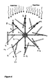
- a preferred embodiment of a prime mover 2 comprises a shaft 4 which is cylindrical and has an axis of rotation running through its centre.
- the shaft 4 comprises eight arms 6 which extend radically from the shaft 4, with each adjacent arm having an angular displacement of 45° from the next arm.
- Each arm 6 comprises at its distal end, a blade 8.
- Each arm 6, comprises an upper 10 and lower 12 member, with each blade 8 being pivotably mounted between the upper 10 and lower 12 members by way of a pivot 14.
- Each arm further includes means to prevent each blade from moving between the first and second positions until the shaft has rotated a prescribed amount, said means comprising a retention bar 16 spanning the space between the upper 10 and lower 12 members.
- the shaft 4 is rotatably mounted on a suitable energy generating apparatus, such as a dynamo electricity generator (not shown). Once mounted, the entire apparatus is positioned in a flow of fluid, such as in a stream of air or under water in tidal or river flow.
- a suitable energy generating apparatus such as a dynamo electricity generator (not shown).
- the prime mover may have braking means (not shown) in order to prevent rotation of the shaft 4 in the flow of fluid, until desired.
- blades are movable between a first position labelled 'A' in which the first surface 18 of the blade 8 is substantially perpendicular to the fluid flow, and presents substantially the greatest surface area for fluid impingement and the greatest drag, to a second position 'B' in which the front surface 18 of the blade 8 is substantially parallel with the flow of fluid, and wherein the blade 8 presents substantially the smallest surface area for fluid impingement, and the least drag.
- the fluid will impinge on the blades in the first position 'A'.
- the pressure of the flow of the fluid on the blades in the first position 'A' causes rotation of the shaft 4, about the central axis.
- the shaft 4 is rotated clockwise.
- the rotational movement of the shaft 4 can then be converted into electrical power or other power by the energy generating apparatus (not shown) to which the shaft 4 is connected.
- the arms 6 are also rotated, which movement begins to move the attached blades 8 from the first position 'A' to the second position 'B'.
- the blades move through intermediate positions labelled 'A-B' whereby the front face 18 of the blade 8 moves from being substantially perpendicular to the flow of fluid to being substantially parallel with the flow of fluid, with the tip 22 of the blade oriented towards the flow of fluid.
- Further rotation of the shaft 4 causes the blades in position 'A-B' to orient such that the rear face 20 of the blade begins to face the flow of fluid, and thus begins to be impinged by the flow of fluid.
- the pressure of the fluid forces the blade to rotate around the pivot 14 into the second position 'B'.
- the tip 22 of the blade is oriented away from the flow of fluid and the front 18 and rear 20 faces of the blade extend substantially parallel with the flow of fluid.
- the surface area of the blade 8 impinged by the flow of fluid is much smaller than in the first position 'A' and hence the drag of the blade 8 is much reduced.
- the blades in the second position 'B' help to reduce the overall drag of the blades 8 on the rotation of the shaft 4 and therefore reduce loss of energy between the linear fluid movement and rotational movement of the shaft 4.
- the arms 6 continue to move as the shaft 4 rotates back to its original position.
- the blades 8 in the second position 'B' are forced by the flow of fluid to pivot back towards the arm 6 to which it is connected and abut the retention bar 16.
- the blades 8 are then moved back to the first position 'A' as the arms 6 are rotated further.
- a second embodiment of the prime mover 2 of the invention includes all the elements of the embodiment described for figures 1 and 2, but include means 24 to limit the movement of the blades 8 to between the first and second positions ('A' and 'B' respectively) only.
- the movement limiting means 24 comprises an upper 26 arm and lower 28 arm extending obliquely from each arm 6 of the prime mover 2.
- the upper arms 26 and lower arms 28 include upper slots 30 and lower slots 32 respectively.
- the movement limiting means 24 further comprises a guide rod 34 which extends through the blades 8 of the prime mover 2 into the upper 30 and lower 32 slots of each movement limiting means 24.
- the guide rods 34 cooperate with the upper 30 and lower 32 slots to limit movement of each blade to between the first position 'A' and second position 'B' as shown in figure 4.
- the guide rod In the first position 'A' the guide rod is located at the proximal end of the upper 30 and lower 32 slots of the movement limiting means 24.
- the guide rod 34 As the shaft 4 of the prime mover 2 is rotated, and the blades are moved from the first 'A' to the second 'B' positions, the guide rod 34 is moved towards the distal end of the movement limiting means 24 between the upper 30 and lower 32 slots. The distal ends of the upper 30 and lower 32 slots are closed to prevent the guide rod 34 from leaving the movement limiting means 24.
- the guide rods 34 prevent the blades 8 from rotating further.
- the guide rods 34 moves back towards the proximal end of the movement limiting means 24.
- the movement limiting means 24 prevent the blades 8 from being moved away from the second position 'B' when the minimum of drag is required on the blades 8, and thus prevents minimum drag configuration and instead adds torque to the prime mover 2.
- the absence of movement limiting means 24 allows each blade 8 to achieve substantially minimum drag when rotated to position B. This minimum drag effects negative torque on the prime mover which is subtracted from the power generated by the prime mover 2.
- the movement limiting means 24 allow each blade to retain an impact angle against the fluid flow through a larger angular displacement, which causes each blade 8 to form an oblique angle to the fluid flow for a longer time period and add to the torque of the prime mover.
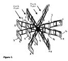
- each arm 6 comprising a single elongate member 36.
- Each elongate member 36 comprises a retention bar 16 which extends above and below the elongate member 36.
- Blades 8 are pivotably connected to the arms 6 by way of pivots 14.
- the prime mover 2 of the third embodiment works in substantially the same manner as the first embodiment described for figures 1 and 2.
- the blade 8 of this embodiment are oriented to be retained in the first position 'A' by the retention bars 16, above and below the elongate members 36.
- each arm 6 comprises two blades 8, spaced apart along the arm 6.
- Each arm comprises two retention bars 16, one for each of the blades 8.
- Each blade comprises its own pivot 14 and is independently movable from the first position 'A' to the second position 'B' as each arm 6 rotates with the shaft 4.
- the mode of operation of the fourth embodiment is substantially identical to that described on the embodiment of figures 1 and 2.
- each arm 6 comprises two blades 8 which are superposed.
- Each arm 6 comprises upper 38 and lower 40 retention bars, to retain each of the blades.
- Each blade 8 comprises its own pivot 14, but in another embodiment (not shown) there may be a single pivot running through both blades.
- the mode of operation of the fifth embodiment is substantially identical to that described for the embodiment of figures 1 and 2.
- movement of the blades 8 from the first position 'A' to the second position 'B' moves the blades from a higher drag orientation to a lower drag orientation in the fluid, to provide for a reduction in the energy loss exhibited by the prime mover in converting the linear fluid flow into rotational movement.
- the shape of the blades 8 is important in order to effect a higher drag in the first position than the second position.
- Preferred blade shapes include wedge-shaped, whether rounded, as shown in Figure 8A, angular, as shown in Figure 8D, rectangular parallelepiped-shaped as shown in Figure 8B (rounded ends) and 8D (angular ends), and blades having a kite-shaped cross-section as shown in Figure 8E.
Landscapes
- Engineering & Computer Science (AREA)
- Combustion & Propulsion (AREA)
- General Engineering & Computer Science (AREA)
- Mechanical Engineering (AREA)
- Chemical & Material Sciences (AREA)
- Sustainable Energy (AREA)
- Life Sciences & Earth Sciences (AREA)
- Sustainable Development (AREA)
- Physics & Mathematics (AREA)
- Fluid Mechanics (AREA)
- Power Engineering (AREA)
- Wind Motors (AREA)
- Other Liquid Machine Or Engine Such As Wave Power Use (AREA)
- Hydraulic Turbines (AREA)
Priority Applications (14)
| Application Number | Priority Date | Filing Date | Title |
|---|---|---|---|
| EP01305525A EP1205661A1 (de) | 2000-11-13 | 2001-06-26 | Windmotor mit senkrechter Drehachse |
| JP2002541250A JP2004520518A (ja) | 2000-11-13 | 2001-10-16 | 垂直軸風力タービン |
| PCT/PH2001/000002 WO2002038954A1 (en) | 2000-11-13 | 2001-10-16 | Vertical axis wind turbine |
| AT01274011T ATE368178T1 (de) | 2000-11-13 | 2001-10-16 | Windmotor mit senkrechter drehachse |
| AU2002214421A AU2002214421B2 (en) | 2000-11-13 | 2001-10-16 | Vertical axis wind turbine |
| KR10-2003-7005585A KR20030048066A (ko) | 2000-11-13 | 2001-10-16 | 수직축 풍력 터빈 |
| CNB018187617A CN100445553C (zh) | 2000-11-13 | 2001-10-16 | 立轴式风力涡轮机 |
| CA2425976A CA2425976C (en) | 2000-11-13 | 2001-10-16 | Vertical axis wind turbine |
| BR0115284-0A BR0115284A (pt) | 2000-11-13 | 2001-10-16 | Turbina de vento com eixo geométrico vertical |
| EP01274011A EP1334276B1 (de) | 2000-11-13 | 2001-10-16 | Windmotor mit senkrechter drehachse |
| AU1442102A AU1442102A (en) | 2000-11-13 | 2001-10-16 | Vertical axis wind turbine |
| US10/399,766 US7083382B2 (en) | 2000-11-13 | 2001-10-16 | Vertical axis wind turbine |
| DE60129581T DE60129581D1 (de) | 2000-11-13 | 2001-10-16 | Windmotor mit senkrechter drehachse |
| JP2006352830A JP2007085358A (ja) | 2000-11-13 | 2006-12-27 | 垂直軸風力タービン |
Applications Claiming Priority (3)
| Application Number | Priority Date | Filing Date | Title |
|---|---|---|---|
| PH313000 | 2000-11-13 | ||
| PH12000003130 | 2000-11-13 | ||
| EP01305525A EP1205661A1 (de) | 2000-11-13 | 2001-06-26 | Windmotor mit senkrechter Drehachse |
Publications (1)
| Publication Number | Publication Date |
|---|---|
| EP1205661A1 true EP1205661A1 (de) | 2002-05-15 |
Family
ID=52573543
Family Applications (2)
| Application Number | Title | Priority Date | Filing Date |
|---|---|---|---|
| EP01305525A Withdrawn EP1205661A1 (de) | 2000-11-13 | 2001-06-26 | Windmotor mit senkrechter Drehachse |
| EP01274011A Expired - Lifetime EP1334276B1 (de) | 2000-11-13 | 2001-10-16 | Windmotor mit senkrechter drehachse |
Family Applications After (1)
| Application Number | Title | Priority Date | Filing Date |
|---|---|---|---|
| EP01274011A Expired - Lifetime EP1334276B1 (de) | 2000-11-13 | 2001-10-16 | Windmotor mit senkrechter drehachse |
Country Status (11)
| Country | Link |
|---|---|
| US (1) | US7083382B2 (de) |
| EP (2) | EP1205661A1 (de) |
| JP (2) | JP2004520518A (de) |
| KR (1) | KR20030048066A (de) |
| CN (1) | CN100445553C (de) |
| AT (1) | ATE368178T1 (de) |
| AU (2) | AU2002214421B2 (de) |
| BR (1) | BR0115284A (de) |
| CA (1) | CA2425976C (de) |
| DE (1) | DE60129581D1 (de) |
| WO (1) | WO2002038954A1 (de) |
Cited By (14)
| Publication number | Priority date | Publication date | Assignee | Title |
|---|---|---|---|---|
| EP1584818A1 (de) * | 2004-04-08 | 2005-10-12 | Wassil Miltchev | Wind- bzw. Wasserbetriebener Genrator / WW-Generator |
| KR100613130B1 (ko) * | 2004-08-10 | 2006-08-17 | 한국해양연구원 | 흐름 발전기용 터빈 |
| DE102006054258A1 (de) | 2006-11-17 | 2008-08-28 | Prikot, Alexander, Dipl.-Ing., 42651 Solingen | Windkraftanlage mit der vertikalen Windrotor-Achse |
| GB2461862A (en) * | 2008-07-11 | 2010-01-20 | John Martin Dunn | Fluid flow kinetic energy station using pressure faces which swing onto stoppers |
| CN102062048A (zh) * | 2011-01-13 | 2011-05-18 | 深圳清华大学研究院 | 大压差阻力型风力机 |
| CN102606373A (zh) * | 2012-04-06 | 2012-07-25 | 丁乃祥 | 弧形水压转动水轮发电机组 |
| CN102758730A (zh) * | 2011-04-26 | 2012-10-31 | 苏俊平 | 活页型垂直轴流体发电机组 |
| CN103233856A (zh) * | 2013-04-07 | 2013-08-07 | 哈尔滨工程大学 | 一种变桨距垂直轴风力机 |
| WO2011084958A3 (en) * | 2010-01-06 | 2014-07-10 | Iq Energy, Inc. | Portable device for generating electric power |
| JP2016514805A (ja) * | 2013-04-11 | 2016-05-23 | オリオン コンサルタンシー アンド ディヴェロップメント ビー.ブイ. | 水車装置と該装置による発電方法 |
| WO2016097432A1 (es) * | 2014-12-15 | 2016-06-23 | Montero Gómez José Manuel | Mecanismo para la conversión del movimiento lineal de un fluido en el movimiento rotacional de un eje |
| EP2984332B1 (de) * | 2012-04-11 | 2018-07-11 | Oryon Consultancy&Development | Wassermühlenvorrichtung und verfahren zur erzeugung von elektrischer energie mittels solch einer vorrichtung |
| CN110594092A (zh) * | 2019-10-05 | 2019-12-20 | 徐文和 | 同轴异步双驱动涡流涡轮机 |
| DE102021002819A1 (de) | 2021-06-01 | 2022-12-15 | Eberhard Löffler | Langsam laufender Windkraftrotor |
Families Citing this family (98)
| Publication number | Priority date | Publication date | Assignee | Title |
|---|---|---|---|---|
| AU157845S (en) * | 2003-10-01 | 2005-03-31 | Shinko Electric Co Ltd | Wind power generator |
| KR100533498B1 (ko) * | 2004-01-13 | 2005-12-06 | 주장식 | 다방향 풍력발전기 |
| USD508893S1 (en) * | 2004-03-18 | 2005-08-30 | Shinko Electric Co., Ltd. | Blade assembly for a wind power generator |
| US6840738B1 (en) * | 2004-04-06 | 2005-01-11 | Marvin L. Swanberg | Feathering turbine apparatus |
| ES2268947B1 (es) * | 2004-12-07 | 2008-02-16 | Maria Elena Novo Vidal | Sistema de obtencion de energia electrica a partir de un fluido en movimiento y del movimiento de las olas. |
| ES2284310B1 (es) * | 2005-03-18 | 2008-08-16 | Maria Elena Novo Vidal | Dispositivo productor de energia electrica a partir de un fluido en movimiento, utilizando un generador de reluctancia variable. |
| MD2991G2 (ro) * | 2005-05-16 | 2006-09-30 | Технический университет Молдовы | Centrală hidroelectrică |
| WO2010011370A1 (en) * | 2008-07-25 | 2010-01-28 | Gulfstream Technologies, Inc. | Apparatus and method for generating electric power from a subsurface water current |
| US20100096856A1 (en) * | 2005-09-12 | 2010-04-22 | Gulfstream Technologies, Inc. | Apparatus and method for generating electric power from a liquid current |
| US8664784B2 (en) * | 2005-09-12 | 2014-03-04 | Gulfstream Technologies, Inc. | Louvered turbine for generating electric power from a water current |
| US7471006B2 (en) * | 2005-09-12 | 2008-12-30 | Gulfstream Technologies, Inc. | Apparatus and method for generating electric power from a subsurface water current |
| US20070104578A1 (en) * | 2005-11-09 | 2007-05-10 | Andrews James W | Radially-sliding wind turbine |
| CN100406719C (zh) * | 2006-02-15 | 2008-07-30 | 严强 | 垂直轴风力发电机叶片攻角调节方法和调节装置 |
| USD569490S1 (en) | 2006-04-06 | 2008-05-20 | Tomion Mark R | Aeroturbine |
| ES2269001B1 (es) * | 2006-06-14 | 2008-03-16 | Universidad De Cantabria | Aeroturbina lenta de eje vertical con orientacion constante de pala. |
| CN100458143C (zh) * | 2006-09-19 | 2009-02-04 | 刘正狮 | 可控制的传动系统及方法 |
| CA2564849A1 (en) * | 2006-10-19 | 2008-04-19 | George R. Friesen | A vertical windmill |
| WO2008056003A1 (es) * | 2006-11-08 | 2008-05-15 | KYUNG, Inyung | Generador eólico |
| ES2347860B1 (es) * | 2006-11-08 | 2011-09-16 | Angel Suarez Del Moral | Generador eolico. |
| US7989973B2 (en) * | 2006-12-22 | 2011-08-02 | Birkestrand Orville J | Fluid-responsive oscillation power generation method and apparatus |
| US7918646B2 (en) * | 2007-01-22 | 2011-04-05 | Lonestar Inventions LLP | High efficiency turbine with variable attack angle foils |
| FR2911926B1 (fr) * | 2007-01-31 | 2012-08-24 | Pierre Andre Marie Dieudonne | Hydrolienne a pales rotatives optimisees. |
| GB2446405B (en) * | 2007-02-09 | 2011-07-27 | David Lawson | Airfoils with automatic pitch control |
| GB2447913A (en) * | 2007-03-27 | 2008-10-01 | Conrad Cooper | Lift and drag driven wind turbine |
| GB2448339A (en) * | 2007-04-12 | 2008-10-15 | Adrian Janssen | Turbine blade adjustment |
| FR2915247A1 (fr) * | 2007-04-17 | 2008-10-24 | Bocaccio Bernard | Eolienne a deblocage ou debrayage automatique |
| US8419367B2 (en) * | 2007-06-08 | 2013-04-16 | David L. Fite | Vertical-axis turbine for capturing the force of moving gases or liquids and a method for its use |
| US8657560B2 (en) * | 2007-09-06 | 2014-02-25 | Watt3 Inc. | Energy extraction device with at least one bank of blades |
| US20090086465A1 (en) * | 2007-09-28 | 2009-04-02 | Andre St-Germain | Wind-powered generator and blade therefor |
| WO2009044386A1 (en) * | 2007-10-03 | 2009-04-09 | Purnomo R Budi | Vertical axis wind turbine |
| GB2453537A (en) * | 2007-10-08 | 2009-04-15 | George Donald Cutler | Turbine with moveable blades |
| US20090121490A1 (en) * | 2007-11-13 | 2009-05-14 | Platzer Maximilian F | Oscillating-Wing Power Generator with Flow-Induced Pitch-Plunge Phasing |
| CN101970803A (zh) * | 2008-02-14 | 2011-02-09 | 丹尼尔·法伯 | 带冠涡轮叶片设计 |
| USD597028S1 (en) * | 2008-02-15 | 2009-07-28 | Dieter R. Sauer, Jr. | Vertical axis wind sail |
| MD3845G2 (ro) * | 2008-03-05 | 2009-09-30 | Технический университет Молдовы | Staţie hidraulică |
| FR2930301B1 (fr) * | 2008-04-18 | 2012-07-13 | Aurore Lembert | Eolienne a axe vertical dont les aubes se mettent "en drapeau" pendant la partie contre-productive de leur rotation. |
| US8038384B2 (en) * | 2008-09-22 | 2011-10-18 | Gene Brown | Omni-directional turbine and method |
| US20100090469A1 (en) * | 2008-10-10 | 2010-04-15 | Sullivan Shaun E | Power-Generator Fan Apparatus, Duct Assembly, Building Construction, and Methods of Use |
| SE0850056A1 (sv) * | 2008-10-27 | 2010-04-28 | Lennart Nilsson | Kraftverk |
| US8373297B2 (en) * | 2009-01-16 | 2013-02-12 | Charles Grigg | Wind turbine generator and motor |
| US20100202883A1 (en) * | 2009-02-09 | 2010-08-12 | Daley Iii Joseph A | Advanced vertical shaft wind turbine power generator |
| US20120045332A1 (en) * | 2009-03-09 | 2012-02-23 | Windjoule Ltd | Vertical axis wind turbine |
| CN102362067A (zh) * | 2009-03-23 | 2012-02-22 | 水力发电有限公司 | 用于水力发电的铰接叶片十字轴涡轮机 |
| JP5626504B2 (ja) * | 2009-05-12 | 2014-11-19 | 正教 横山 | 風水車 |
| US8480363B2 (en) * | 2009-06-03 | 2013-07-09 | Thomas Mellus Fenaughty | Self-starting turbine with dual position vanes |
| TW201102496A (en) * | 2009-07-09 | 2011-01-16 | Yao-Mo Liao | Power transferring post, universal revolving blade set of power generation device and the assembly thereof |
| US9115697B2 (en) * | 2009-08-25 | 2015-08-25 | Jeffrey M. Lucas | Fluid interacting device |
| US10851758B2 (en) * | 2009-10-02 | 2020-12-01 | Jose Ramon Santana | Hydrokinetic transport wheel mount |
| CN102713255B (zh) * | 2010-01-08 | 2015-11-25 | H·德鲁兹 | 用于发电的水轮 |
| EP2556244B1 (de) | 2010-01-14 | 2014-05-21 | Daniel P. Coffey | Gerät zum umsetzen von windenergie |
| US20140341736A1 (en) * | 2010-01-22 | 2014-11-20 | Jon Jay Howard | Sail wind turbine |
| US20110194938A1 (en) * | 2010-02-11 | 2011-08-11 | Livingston Troy W | Segmented wind turbine airfoil/blade |
| US8016544B1 (en) * | 2010-03-08 | 2011-09-13 | Nguyen Huy T | Vertical windmill |
| US20110223023A1 (en) * | 2010-03-11 | 2011-09-15 | Melvin Don Carden | Mechanical rotor |
| EP2381090A3 (de) * | 2010-04-25 | 2012-10-03 | Iiapia | Hebelwirkung maximierendes Wasserrad mit vertikale Achse |
| JP4753399B1 (ja) * | 2010-06-09 | 2011-08-24 | 吉二 玉津 | 風切羽翼で回転抵抗を減じた水風車 |
| AT510238B1 (de) | 2010-07-27 | 2012-06-15 | Mario Kinelly | Rotor für ein windrad |
| KR101217314B1 (ko) * | 2010-11-05 | 2012-12-31 | 강옥례 | 풍향조절 날개형 수직축 풍차 |
| US20120207601A1 (en) * | 2011-02-11 | 2012-08-16 | Wang yu-han | Rotor having a Lower Resistance or Drag |
| US9006919B2 (en) * | 2011-03-08 | 2015-04-14 | Gerard J. Lynch | Adaptive hydrokinetic energy harvesting system |
| ITFI20110071A1 (it) * | 2011-04-14 | 2012-10-15 | Abdullah Amirian | Dispositivo idraulico di tipo reversibile per la conversione di energia. |
| US20120301297A1 (en) * | 2011-05-28 | 2012-11-29 | Marion Ludwick | Fluid turbine device for power generation |
| JP2013002437A (ja) * | 2011-06-16 | 2013-01-07 | Hajime Gokan | 発電用水車 |
| TWI486520B (zh) * | 2011-06-30 | 2015-06-01 | Univ Kun Shan | Roll-type blades |
| WO2013005870A1 (ko) * | 2011-07-04 | 2013-01-10 | Jeong Eul Yong | 편익 회전 날개형 수직축 풍력 발전기 |
| JP6032698B2 (ja) * | 2011-07-05 | 2016-11-30 | 合同会社アルバトロス・テクノロジー | 自然エネルギー取出装置 |
| US9062657B2 (en) * | 2011-08-02 | 2015-06-23 | Eugene Lawrence Sobocinski | Horizontally oriented wind turbine |
| US8613587B2 (en) * | 2012-02-21 | 2013-12-24 | Francis X. Reilly | Rotor assembly for a turbine |
| US9938958B2 (en) | 2012-07-19 | 2018-04-10 | Humberto Antonio RUBIO | Vertical axis wind and hydraulic turbine with flow control |
| MD589Z (ro) * | 2012-09-20 | 2013-08-31 | Технический университет Молдовы | Staţie hidraulică |
| FR2996606A1 (fr) * | 2012-10-10 | 2014-04-11 | Pierre Armand Thomas | Dispositif de conversion d'energie eolienne en energie mecanique ou electrique |
| BE1021091B1 (nl) * | 2012-10-11 | 2015-11-27 | VAN ROMPAY BOUDEWIJN GABRIëL | Inrichting voor het opwekken van hydro-elektrische energie |
| CN102979657A (zh) * | 2012-11-30 | 2013-03-20 | 蔡长运 | 利用海浪和海水流动能发电的设备 |
| JP2014134190A (ja) * | 2013-01-08 | 2014-07-24 | Masahito Saito | 反転羽根式水車 |
| CN103696896A (zh) * | 2013-03-01 | 2014-04-02 | 张儒海 | 自然能源动力多功能发电装置 |
| US20140308127A1 (en) * | 2013-04-10 | 2014-10-16 | Calvin Chunliang Lee | Airfoil blades with self-alignment mechanisms for cross-flow turbines |
| US9404477B2 (en) * | 2013-06-10 | 2016-08-02 | Jerry Austin Carter | Proportional moving air power transmission and energy collection and control system |
| GB2519214B8 (en) * | 2013-10-10 | 2017-03-01 | Kirloskar Integrated Tech Ltd | A power generation system |
| CN103590971A (zh) * | 2013-10-22 | 2014-02-19 | 倪忠 | 发电装置 |
| CN103541868A (zh) * | 2013-11-08 | 2014-01-29 | 刘宣智 | 多功能全效风力发电机 |
| CN104653381A (zh) * | 2013-11-19 | 2015-05-27 | 邹秋苟 | 一种离心式水下动力机 |
| US9765636B2 (en) * | 2014-03-05 | 2017-09-19 | Baker Hughes Incorporated | Flow rate responsive turbine blades and related methods |
| CN103953500A (zh) * | 2014-05-21 | 2014-07-30 | 北京航空航天大学 | 一种垂直轴风力机 |
| DE102014015580A1 (de) * | 2014-10-15 | 2016-04-21 | Hans Erich Gunder | Schwingblätter für Rechteck- oder Vetikalachskonverter zum Einsatz in strömendem Wasser. |
| US20190242361A1 (en) * | 2014-11-08 | 2019-08-08 | SaeHeum Song | Apparatus and Method for Deriving Useful Energy from a Flowing Fluid |
| CN107110116A (zh) * | 2014-12-17 | 2017-08-29 | 乌巴尔多·贝纳迪 | 具有轨道运行轴的用于转换能量的系统 |
| KR101868973B1 (ko) * | 2016-07-28 | 2018-08-09 | 주식회사 서준 | 수력발전장치 |
| CN106089551B (zh) * | 2016-08-17 | 2018-11-20 | 重庆齿轮箱有限责任公司 | 一种水流动力发电装置 |
| CN108223238B (zh) * | 2017-12-29 | 2020-05-22 | 清华大学 | 一种浪轮机及海洋浪轮机式水能发电装置 |
| TWM562339U (zh) * | 2018-03-19 | 2018-06-21 | True Ten Industrial Co Ltd | 驅動扇葉組 |
| US10920751B2 (en) * | 2018-12-12 | 2021-02-16 | Ziaur Rahman | Orthogonal turbine having a speed adjusting member |
| TWI793349B (zh) * | 2019-07-12 | 2023-02-21 | 黃國彰 | 流力葉片裝置 |
| CN110541789A (zh) * | 2019-09-04 | 2019-12-06 | 施焱森 | 采用组合叶板水平轴动力机且具有能量增效功能的动力源自锁定海洋能发电站 |
| CN110761934A (zh) * | 2019-09-24 | 2020-02-07 | 重庆交通大学 | 一种可随水位升降的自浮式低流速河流发电装置 |
| WO2021112993A1 (en) * | 2019-12-04 | 2021-06-10 | Cummings Michael Scot | Reactive, reversible blade turbine for power generation and pumping water |
| CN113406116B (zh) * | 2021-05-21 | 2022-09-27 | 中国工程物理研究院核物理与化学研究所 | 一种空心涡轮叶片检测用的大容量样品承载装置 |
| US11795908B2 (en) * | 2021-12-02 | 2023-10-24 | Carl Almond Fausett | Vertical-axis renewable-power generator |
| CN114215679B (zh) * | 2021-12-14 | 2024-05-03 | 上海炅海新能源科技有限公司 | 一种半潜式潮流发电装置 |
Citations (11)
| Publication number | Priority date | Publication date | Assignee | Title |
|---|---|---|---|---|
| US2128592A (en) * | 1936-09-23 | 1938-08-30 | Michael D Mushkin | Current-propelled turbine |
| DE2718608A1 (de) * | 1977-04-27 | 1978-11-02 | Max Dipl Phys Dr Rer N Fenkner | Windkraftmaschine |
| GB2008202A (en) * | 1977-10-12 | 1979-05-31 | Herter E Herter G | Wind Turbine |
| FR2426813A1 (fr) * | 1978-05-26 | 1979-12-21 | Couret Bernard | Dispositif de captage et regulation d'energie d'un fluide en mouvement |
| US4191506A (en) * | 1977-12-20 | 1980-03-04 | Packham Lester M | Propeller and impeller constructions |
| GB2068472A (en) * | 1980-02-06 | 1981-08-12 | Cofimco Sas | Axial paddle-wheel fan |
| US4468169A (en) * | 1982-08-18 | 1984-08-28 | Williams Dennis L | Regulated high torque flexible bladed wind wheel |
| GB2241747A (en) * | 1990-02-24 | 1991-09-11 | John Jason Paul Goodden | Turbine or impeller rotor |
| WO1992001866A1 (en) * | 1990-07-16 | 1992-02-06 | Ernster Melvin J | Fluid-augmented free-vortex power generating apparatus |
| US5256034A (en) * | 1991-04-19 | 1993-10-26 | Sultzbaugh John S | Variable pitch propeller for use in conjunction with a vertical axis wind turbine |
| US5266006A (en) * | 1993-02-25 | 1993-11-30 | Tsui I Hua | Windmill with removable wind vane plates arranged in multi-rows-and-lines |
Family Cites Families (9)
| Publication number | Priority date | Publication date | Assignee | Title |
|---|---|---|---|---|
| US1225033A (en) * | 1916-04-15 | 1917-05-08 | Charles C Jackson | Wind-wheel. |
| US4052134A (en) * | 1976-01-15 | 1977-10-04 | Rollin Douglas Rumsey | Vertical axis wind turbine motor |
| US4137009A (en) * | 1976-11-05 | 1979-01-30 | Board Of Regents University Of Nevada System | Pivoted blade barrel rotor wind turbine |
| US4247251A (en) | 1978-05-17 | 1981-01-27 | Wuenscher Hans F | Cycloidal fluid flow engine |
| US4618313A (en) | 1980-02-06 | 1986-10-21 | Cofimco S.R.L. | Axial propeller with increased effective displacement of air whose blades are not twisted |
| US4383801A (en) * | 1981-03-02 | 1983-05-17 | Pryor Dale H | Wind turbine with adjustable air foils |
| KR830008035A (ko) | 1981-10-19 | 1983-11-09 | 김영순 | 미풍풍력 동력 체제 |
| US5193978A (en) * | 1991-09-23 | 1993-03-16 | Bill Gutierrez | Articulated blade with automatic pitch and camber control |
| US5503525A (en) * | 1992-08-12 | 1996-04-02 | The University Of Melbourne | Pitch-regulated vertical access wind turbine |
-
2001
- 2001-06-26 EP EP01305525A patent/EP1205661A1/de not_active Withdrawn
- 2001-10-16 CA CA2425976A patent/CA2425976C/en not_active Expired - Fee Related
- 2001-10-16 DE DE60129581T patent/DE60129581D1/de not_active Expired - Lifetime
- 2001-10-16 AU AU2002214421A patent/AU2002214421B2/en not_active Ceased
- 2001-10-16 AT AT01274011T patent/ATE368178T1/de not_active IP Right Cessation
- 2001-10-16 US US10/399,766 patent/US7083382B2/en not_active Expired - Fee Related
- 2001-10-16 JP JP2002541250A patent/JP2004520518A/ja active Pending
- 2001-10-16 CN CNB018187617A patent/CN100445553C/zh not_active Expired - Fee Related
- 2001-10-16 KR KR10-2003-7005585A patent/KR20030048066A/ko not_active Ceased
- 2001-10-16 EP EP01274011A patent/EP1334276B1/de not_active Expired - Lifetime
- 2001-10-16 AU AU1442102A patent/AU1442102A/xx active Pending
- 2001-10-16 BR BR0115284-0A patent/BR0115284A/pt active Search and Examination
- 2001-10-16 WO PCT/PH2001/000002 patent/WO2002038954A1/en not_active Ceased
-
2006
- 2006-12-27 JP JP2006352830A patent/JP2007085358A/ja active Pending
Patent Citations (11)
| Publication number | Priority date | Publication date | Assignee | Title |
|---|---|---|---|---|
| US2128592A (en) * | 1936-09-23 | 1938-08-30 | Michael D Mushkin | Current-propelled turbine |
| DE2718608A1 (de) * | 1977-04-27 | 1978-11-02 | Max Dipl Phys Dr Rer N Fenkner | Windkraftmaschine |
| GB2008202A (en) * | 1977-10-12 | 1979-05-31 | Herter E Herter G | Wind Turbine |
| US4191506A (en) * | 1977-12-20 | 1980-03-04 | Packham Lester M | Propeller and impeller constructions |
| FR2426813A1 (fr) * | 1978-05-26 | 1979-12-21 | Couret Bernard | Dispositif de captage et regulation d'energie d'un fluide en mouvement |
| GB2068472A (en) * | 1980-02-06 | 1981-08-12 | Cofimco Sas | Axial paddle-wheel fan |
| US4468169A (en) * | 1982-08-18 | 1984-08-28 | Williams Dennis L | Regulated high torque flexible bladed wind wheel |
| GB2241747A (en) * | 1990-02-24 | 1991-09-11 | John Jason Paul Goodden | Turbine or impeller rotor |
| WO1992001866A1 (en) * | 1990-07-16 | 1992-02-06 | Ernster Melvin J | Fluid-augmented free-vortex power generating apparatus |
| US5256034A (en) * | 1991-04-19 | 1993-10-26 | Sultzbaugh John S | Variable pitch propeller for use in conjunction with a vertical axis wind turbine |
| US5266006A (en) * | 1993-02-25 | 1993-11-30 | Tsui I Hua | Windmill with removable wind vane plates arranged in multi-rows-and-lines |
Cited By (19)
| Publication number | Priority date | Publication date | Assignee | Title |
|---|---|---|---|---|
| EP1584818A1 (de) * | 2004-04-08 | 2005-10-12 | Wassil Miltchev | Wind- bzw. Wasserbetriebener Genrator / WW-Generator |
| KR100613130B1 (ko) * | 2004-08-10 | 2006-08-17 | 한국해양연구원 | 흐름 발전기용 터빈 |
| DE102006054258A1 (de) | 2006-11-17 | 2008-08-28 | Prikot, Alexander, Dipl.-Ing., 42651 Solingen | Windkraftanlage mit der vertikalen Windrotor-Achse |
| GB2461862A (en) * | 2008-07-11 | 2010-01-20 | John Martin Dunn | Fluid flow kinetic energy station using pressure faces which swing onto stoppers |
| WO2011084958A3 (en) * | 2010-01-06 | 2014-07-10 | Iq Energy, Inc. | Portable device for generating electric power |
| CN102062048A (zh) * | 2011-01-13 | 2011-05-18 | 深圳清华大学研究院 | 大压差阻力型风力机 |
| CN102062048B (zh) * | 2011-01-13 | 2013-02-13 | 深圳清华大学研究院 | 大压差阻力型风力机 |
| CN102758730A (zh) * | 2011-04-26 | 2012-10-31 | 苏俊平 | 活页型垂直轴流体发电机组 |
| CN102606373A (zh) * | 2012-04-06 | 2012-07-25 | 丁乃祥 | 弧形水压转动水轮发电机组 |
| EP2984332B1 (de) * | 2012-04-11 | 2018-07-11 | Oryon Consultancy&Development | Wassermühlenvorrichtung und verfahren zur erzeugung von elektrischer energie mittels solch einer vorrichtung |
| CN103233856A (zh) * | 2013-04-07 | 2013-08-07 | 哈尔滨工程大学 | 一种变桨距垂直轴风力机 |
| CN103233856B (zh) * | 2013-04-07 | 2015-06-17 | 哈尔滨工程大学 | 一种变桨距垂直轴风力机 |
| JP2016514805A (ja) * | 2013-04-11 | 2016-05-23 | オリオン コンサルタンシー アンド ディヴェロップメント ビー.ブイ. | 水車装置と該装置による発電方法 |
| WO2016097432A1 (es) * | 2014-12-15 | 2016-06-23 | Montero Gómez José Manuel | Mecanismo para la conversión del movimiento lineal de un fluido en el movimiento rotacional de un eje |
| CN110594092A (zh) * | 2019-10-05 | 2019-12-20 | 徐文和 | 同轴异步双驱动涡流涡轮机 |
| CN110594092B (zh) * | 2019-10-05 | 2021-03-23 | 徐文和 | 同轴异步双驱动涡流涡轮机 |
| WO2021062909A1 (zh) * | 2019-10-05 | 2021-04-08 | 徐文和 | 同轴异步双驱动涡流涡轮机 |
| DE102021002819A1 (de) | 2021-06-01 | 2022-12-15 | Eberhard Löffler | Langsam laufender Windkraftrotor |
| DE102021002819B4 (de) * | 2021-06-01 | 2025-05-08 | Eberhard Löffler | Langsam laufender Windkraftrotor |
Also Published As
| Publication number | Publication date |
|---|---|
| AU1442102A (en) | 2002-05-21 |
| JP2007085358A (ja) | 2007-04-05 |
| EP1334276A1 (de) | 2003-08-13 |
| US7083382B2 (en) | 2006-08-01 |
| ATE368178T1 (de) | 2007-08-15 |
| US20030185666A1 (en) | 2003-10-02 |
| AU2002214421B2 (en) | 2005-02-17 |
| CN1474911A (zh) | 2004-02-11 |
| BR0115284A (pt) | 2004-02-17 |
| WO2002038954A1 (en) | 2002-05-16 |
| EP1334276B1 (de) | 2007-07-25 |
| KR20030048066A (ko) | 2003-06-18 |
| JP2004520518A (ja) | 2004-07-08 |
| CA2425976A1 (en) | 2002-05-16 |
| CA2425976C (en) | 2012-01-03 |
| CN100445553C (zh) | 2008-12-24 |
| DE60129581D1 (de) | 2007-09-06 |
Similar Documents
| Publication | Publication Date | Title |
|---|---|---|
| US7083382B2 (en) | Vertical axis wind turbine | |
| AU2002214421A1 (en) | Vertical axis wind turbine | |
| Paraschivoiu | Wind turbine design: with emphasis on Darrieus concept | |
| US20100032954A1 (en) | Wind turbine | |
| CN104514680B (zh) | 发电效率提高的可变型翼潮汐风力发电机 | |
| Dong et al. | Development of a 300 kW horizontal-axis tidal stream energy conversion system with adaptive variable-pitch turbine and direct-drive PMSG | |
| US10941749B2 (en) | Speed converter-controlled river turbines | |
| Moniruzzaman et al. | Hydrokinetic Turbine Technology and Its Prospect in Bangladesh: A | |
| Whittaker et al. | THE ISLAY WAVE POWER PROJECT: AN ENGINEERING PERSPECTIVE. | |
| Fedak et al. | Determination of the number of Vertical Axis Wind Turbine blades based on power spectrum | |
| US20220173648A1 (en) | Mech-elect generator | |
| KR101198580B1 (ko) | 풍력발전기의 날개 및 풍력발전장치 | |
| KR101295812B1 (ko) | 듀얼 블레이드형 해양 발전장치 | |
| Whittaker | Learning form the Islay wave power plant | |
| CN206368767U (zh) | 多轴同心叶片自锁式涡轮机 | |
| NZ239140A (en) | Vertical axis windmill with paired feathering and | |
| HK1062470A (en) | Vertical axis wind turbine | |
| KR102171967B1 (ko) | 고효율 풍력발전장치 | |
| GB2462880A (en) | Horizontal axis cross flow turbine | |
| CN106401838A (zh) | 多轴同心叶片自锁式涡轮机 | |
| Rusianto et al. | Performance of the Pumpkin Wind Turbine | |
| Kumar et al. | Oscillating Water Column as Clean Energy Source for Sustainable Power Generation | |
| Maisuria et al. | Experimental Analysis of Combine Darrious And Savonius Wind Turbine | |
| Salunkhe et al. | Offshore Floating Wind Turbine | |
| Hansen | General introduction to wind turbines |
Legal Events
| Date | Code | Title | Description |
|---|---|---|---|
| PUAI | Public reference made under article 153(3) epc to a published international application that has entered the european phase |
Free format text: ORIGINAL CODE: 0009012 |
|
| AK | Designated contracting states |
Kind code of ref document: A1 Designated state(s): AT BE CH CY DE DK ES FI FR GB GR IE IT LI LU MC NL PT SE TR |
|
| AX | Request for extension of the european patent |
Free format text: AL;LT;LV;MK;RO;SI |
|
| AKX | Designation fees paid | ||
| STAA | Information on the status of an ep patent application or granted ep patent |
Free format text: STATUS: THE APPLICATION IS DEEMED TO BE WITHDRAWN |
|
| 18D | Application deemed to be withdrawn |
Effective date: 20020516 |