EP1205670A2 - Bloc distributeur pour liquides et gaz - Google Patents
Bloc distributeur pour liquides et gaz Download PDFInfo
- Publication number
- EP1205670A2 EP1205670A2 EP01126695A EP01126695A EP1205670A2 EP 1205670 A2 EP1205670 A2 EP 1205670A2 EP 01126695 A EP01126695 A EP 01126695A EP 01126695 A EP01126695 A EP 01126695A EP 1205670 A2 EP1205670 A2 EP 1205670A2
- Authority
- EP
- European Patent Office
- Prior art keywords
- channels
- layer
- layers
- width
- channel
- Prior art date
- Legal status (The legal status is an assumption and is not a legal conclusion. Google has not performed a legal analysis and makes no representation as to the accuracy of the status listed.)
- Withdrawn
Links
Images




Classifications
-
- F—MECHANICAL ENGINEERING; LIGHTING; HEATING; WEAPONS; BLASTING
- F16—ENGINEERING ELEMENTS AND UNITS; GENERAL MEASURES FOR PRODUCING AND MAINTAINING EFFECTIVE FUNCTIONING OF MACHINES OR INSTALLATIONS; THERMAL INSULATION IN GENERAL
- F16K—VALVES; TAPS; COCKS; ACTUATING-FLOATS; DEVICES FOR VENTING OR AERATING
- F16K99/00—Subject matter not provided for in other groups of this subclass
- F16K99/0001—Microvalves
-
- B—PERFORMING OPERATIONS; TRANSPORTING
- B01—PHYSICAL OR CHEMICAL PROCESSES OR APPARATUS IN GENERAL
- B01F—MIXING, e.g. DISSOLVING, EMULSIFYING OR DISPERSING
- B01F25/00—Flow mixers; Mixers for falling materials, e.g. solid particles
- B01F25/40—Static mixers
- B01F25/42—Static mixers in which the mixing is affected by moving the components jointly in changing directions, e.g. in tubes provided with baffles or obstructions
- B01F25/421—Static mixers in which the mixing is affected by moving the components jointly in changing directions, e.g. in tubes provided with baffles or obstructions by moving the components in a convoluted or labyrinthine path
- B01F25/422—Static mixers in which the mixing is affected by moving the components jointly in changing directions, e.g. in tubes provided with baffles or obstructions by moving the components in a convoluted or labyrinthine path between stacked plates, e.g. grooved or perforated plates
-
- B—PERFORMING OPERATIONS; TRANSPORTING
- B01—PHYSICAL OR CHEMICAL PROCESSES OR APPARATUS IN GENERAL
- B01F—MIXING, e.g. DISSOLVING, EMULSIFYING OR DISPERSING
- B01F33/00—Other mixers; Mixing plants; Combinations of mixers
- B01F33/30—Micromixers
-
- B—PERFORMING OPERATIONS; TRANSPORTING
- B01—PHYSICAL OR CHEMICAL PROCESSES OR APPARATUS IN GENERAL
- B01L—CHEMICAL OR PHYSICAL LABORATORY APPARATUS FOR GENERAL USE
- B01L3/00—Containers or dishes for laboratory use, e.g. laboratory glassware; Droppers
- B01L3/50—Containers for the purpose of retaining a material to be analysed, e.g. test tubes
- B01L3/502—Containers for the purpose of retaining a material to be analysed, e.g. test tubes with fluid transport, e.g. in multi-compartment structures
- B01L3/5027—Containers for the purpose of retaining a material to be analysed, e.g. test tubes with fluid transport, e.g. in multi-compartment structures by integrated microfluidic structures, i.e. dimensions of channels and chambers are such that surface tension forces are important, e.g. lab-on-a-chip
-
- B—PERFORMING OPERATIONS; TRANSPORTING
- B01—PHYSICAL OR CHEMICAL PROCESSES OR APPARATUS IN GENERAL
- B01L—CHEMICAL OR PHYSICAL LABORATORY APPARATUS FOR GENERAL USE
- B01L3/00—Containers or dishes for laboratory use, e.g. laboratory glassware; Droppers
- B01L3/50—Containers for the purpose of retaining a material to be analysed, e.g. test tubes
- B01L3/502—Containers for the purpose of retaining a material to be analysed, e.g. test tubes with fluid transport, e.g. in multi-compartment structures
- B01L3/5027—Containers for the purpose of retaining a material to be analysed, e.g. test tubes with fluid transport, e.g. in multi-compartment structures by integrated microfluidic structures, i.e. dimensions of channels and chambers are such that surface tension forces are important, e.g. lab-on-a-chip
- B01L3/502707—Containers for the purpose of retaining a material to be analysed, e.g. test tubes with fluid transport, e.g. in multi-compartment structures by integrated microfluidic structures, i.e. dimensions of channels and chambers are such that surface tension forces are important, e.g. lab-on-a-chip characterised by the manufacture of the container or its components
-
- F—MECHANICAL ENGINEERING; LIGHTING; HEATING; WEAPONS; BLASTING
- F16—ENGINEERING ELEMENTS AND UNITS; GENERAL MEASURES FOR PRODUCING AND MAINTAINING EFFECTIVE FUNCTIONING OF MACHINES OR INSTALLATIONS; THERMAL INSULATION IN GENERAL
- F16K—VALVES; TAPS; COCKS; ACTUATING-FLOATS; DEVICES FOR VENTING OR AERATING
- F16K99/00—Subject matter not provided for in other groups of this subclass
- F16K99/0001—Microvalves
- F16K99/0003—Constructional types of microvalves; Details of the cutting-off member
- F16K99/003—Valves for single use only
-
- F—MECHANICAL ENGINEERING; LIGHTING; HEATING; WEAPONS; BLASTING
- F16—ENGINEERING ELEMENTS AND UNITS; GENERAL MEASURES FOR PRODUCING AND MAINTAINING EFFECTIVE FUNCTIONING OF MACHINES OR INSTALLATIONS; THERMAL INSULATION IN GENERAL
- F16K—VALVES; TAPS; COCKS; ACTUATING-FLOATS; DEVICES FOR VENTING OR AERATING
- F16K99/00—Subject matter not provided for in other groups of this subclass
- F16K99/0001—Microvalves
- F16K99/0034—Operating means specially adapted for microvalves
-
- F—MECHANICAL ENGINEERING; LIGHTING; HEATING; WEAPONS; BLASTING
- F16—ENGINEERING ELEMENTS AND UNITS; GENERAL MEASURES FOR PRODUCING AND MAINTAINING EFFECTIVE FUNCTIONING OF MACHINES OR INSTALLATIONS; THERMAL INSULATION IN GENERAL
- F16K—VALVES; TAPS; COCKS; ACTUATING-FLOATS; DEVICES FOR VENTING OR AERATING
- F16K99/00—Subject matter not provided for in other groups of this subclass
- F16K99/0001—Microvalves
- F16K99/0034—Operating means specially adapted for microvalves
- F16K99/0036—Operating means specially adapted for microvalves operated by temperature variations
- F16K99/004—Operating means specially adapted for microvalves operated by temperature variations using radiation
-
- B—PERFORMING OPERATIONS; TRANSPORTING
- B01—PHYSICAL OR CHEMICAL PROCESSES OR APPARATUS IN GENERAL
- B01F—MIXING, e.g. DISSOLVING, EMULSIFYING OR DISPERSING
- B01F2101/00—Mixing characterised by the nature of the mixed materials or by the application field
- B01F2101/23—Mixing of laboratory samples e.g. in preparation of analysing or testing properties of materials
-
- B—PERFORMING OPERATIONS; TRANSPORTING
- B01—PHYSICAL OR CHEMICAL PROCESSES OR APPARATUS IN GENERAL
- B01L—CHEMICAL OR PHYSICAL LABORATORY APPARATUS FOR GENERAL USE
- B01L2300/00—Additional constructional details
- B01L2300/08—Geometry, shape and general structure
- B01L2300/0809—Geometry, shape and general structure rectangular shaped
- B01L2300/0816—Cards, e.g. flat sample carriers usually with flow in two horizontal directions
-
- B—PERFORMING OPERATIONS; TRANSPORTING
- B01—PHYSICAL OR CHEMICAL PROCESSES OR APPARATUS IN GENERAL
- B01L—CHEMICAL OR PHYSICAL LABORATORY APPARATUS FOR GENERAL USE
- B01L2300/00—Additional constructional details
- B01L2300/08—Geometry, shape and general structure
- B01L2300/0861—Configuration of multiple channels and/or chambers in a single devices
- B01L2300/087—Multiple sequential chambers
-
- B—PERFORMING OPERATIONS; TRANSPORTING
- B01—PHYSICAL OR CHEMICAL PROCESSES OR APPARATUS IN GENERAL
- B01L—CHEMICAL OR PHYSICAL LABORATORY APPARATUS FOR GENERAL USE
- B01L2300/00—Additional constructional details
- B01L2300/08—Geometry, shape and general structure
- B01L2300/0861—Configuration of multiple channels and/or chambers in a single devices
- B01L2300/0874—Three dimensional network
-
- B—PERFORMING OPERATIONS; TRANSPORTING
- B01—PHYSICAL OR CHEMICAL PROCESSES OR APPARATUS IN GENERAL
- B01L—CHEMICAL OR PHYSICAL LABORATORY APPARATUS FOR GENERAL USE
- B01L2300/00—Additional constructional details
- B01L2300/08—Geometry, shape and general structure
- B01L2300/0887—Laminated structure
-
- B—PERFORMING OPERATIONS; TRANSPORTING
- B01—PHYSICAL OR CHEMICAL PROCESSES OR APPARATUS IN GENERAL
- B01L—CHEMICAL OR PHYSICAL LABORATORY APPARATUS FOR GENERAL USE
- B01L2400/00—Moving or stopping fluids
- B01L2400/04—Moving fluids with specific forces or mechanical means
- B01L2400/0403—Moving fluids with specific forces or mechanical means specific forces
- B01L2400/0406—Moving fluids with specific forces or mechanical means specific forces capillary forces
-
- F—MECHANICAL ENGINEERING; LIGHTING; HEATING; WEAPONS; BLASTING
- F16—ENGINEERING ELEMENTS AND UNITS; GENERAL MEASURES FOR PRODUCING AND MAINTAINING EFFECTIVE FUNCTIONING OF MACHINES OR INSTALLATIONS; THERMAL INSULATION IN GENERAL
- F16K—VALVES; TAPS; COCKS; ACTUATING-FLOATS; DEVICES FOR VENTING OR AERATING
- F16K99/00—Subject matter not provided for in other groups of this subclass
- F16K2099/0073—Fabrication methods specifically adapted for microvalves
- F16K2099/008—Multi-layer fabrications
-
- F—MECHANICAL ENGINEERING; LIGHTING; HEATING; WEAPONS; BLASTING
- F16—ENGINEERING ELEMENTS AND UNITS; GENERAL MEASURES FOR PRODUCING AND MAINTAINING EFFECTIVE FUNCTIONING OF MACHINES OR INSTALLATIONS; THERMAL INSULATION IN GENERAL
- F16K—VALVES; TAPS; COCKS; ACTUATING-FLOATS; DEVICES FOR VENTING OR AERATING
- F16K99/00—Subject matter not provided for in other groups of this subclass
- F16K2099/0082—Microvalves adapted for a particular use
- F16K2099/0084—Chemistry or biology, e.g. "lab-on-a-chip" technology
Definitions
- the present invention relates to a distributor plate for liquids and gases and in particular a distributor plate for distributing very small liquids and / or Gas quantities.
- the present invention particularly provides a liquid distribution plate and / or gases, which consists of at least one layer, in which Layer or layers of a plurality of first elongated channels with one first geometric formation essentially in a first direction is formed, and also having a plurality of second elongated channels a second geometric configuration essentially in a second direction is trained.
- Such layers can be particularly small if they are very small
- such a layer can be used in a simple manner suitable holes in spaces between adjacent Channels at least a first and second channel are connected to each other, where appropriate specifications by the intended use of the Distribution plate can be taken into account in an equally simple way.
- the present invention also provides a distribution plate for Liquids or gases with a layer sequence ready, the layer sequence suitably consists of a first layer in which a plurality of first elongated channels with a first geometric formation essentially in is formed in a first direction and also at least from a second Layer in which a plurality of second elongated channels with a second geometric formation essentially in a second direction is trained.
- the layer sequence suitably consists of a first layer in which a plurality of first elongated channels with a first geometric formation essentially in is formed in a first direction and also at least from a second Layer in which a plurality of second elongated channels with a second geometric formation essentially in a second direction is trained.
- at least two layers of the first and second layer arranged one above the other, with suitable bores in Spaces one above the other and / or channels of the first and / or second layer at least a first and second channel are interconnectable.
- At least one channel can be provided simply, quickly and inexpensively, which is suitable for a liquid or a gas from at least a first position to lead to at least a second position.
- a distributor plate it is possible in a simple manner to couple two or more miniaturized components, so that one Liquid and / or a gas is transported from one component to the other component and can be distributed to the other component at the same time.
- the present invention also provides, in particular, a distributor plate for liquids and / or gases which is suitable for coupling standardized components of a modular system to one another, the distributor plate being designed in accordance with the standardizations and norms of the modular system.
- the geometry of the channels of the distributor plate is adapted to the corresponding requirements of the modular system.
- the openings of the distributor plate required for this are also provided on the top and / or bottom of the distributor plate in accordance with the requirements of the modular system.
- the distributor plate for coupling two components can advantageously be connected between the two components.
- a distributor plate according to the invention is also particularly suitable for connecting openings of only one component to one another, or for connecting two or more components to one another, which can be arranged on the top and / or bottom of the distributor plate.
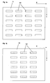
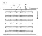
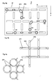
- the first layer 11 consists of a large number of elongated layers 11 in a first direction X channels 111 arranged in rows in the X direction are arranged one behind the other, the distances between the channels in the Rows are slightly smaller than the length of the channels. The distance between the Rows are also slightly smaller than the length of the channels.
- the second layer 12 also consists of a plurality of elongated channels 121, which are also in the are essentially formed in a first direction X and in a plurality of Rows are arranged one behind the other in the X direction, the channels 121 of the second layer 12 according to the invention arranged at positions on layer 12 are the spaces between two channels 111 in the X direction of the Correspond to layer 11.
- the channels 111 of the first layer 11 and the channels 121 the second layer 12 are also designed and positioned such that when the first and second layers are arranged one above the other, the ends of the channels 121 and 111 overlap, which is shown in FIG. 2.
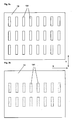
- 3a and 3b show a third layer 13 and a fourth layer 14 of the first Execution of the present invention analogous to that described above Layers 11 and 12 are formed, with the difference that the channels 131 and 141 are formed substantially in a second direction Y, which is different from the first direction X differs. Suitably close the first direction X and the second direction Y an angle of 90 °.
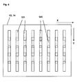
- Fig. 4 shows the one above the other arranged layers 13 and 14 with channels 131 and 141, which are also how the channels 111 and 121 each overlap at their ends and also each between spaces between two channels of the other layer are arranged.
- Channels 131 and 141 of the third and fourth layers are also such in FIGS Layers 13 and 14 arranged that when layers 11, 12, 13 and 14 are arranged one above the other, the ends of the channels 131 and 141 the ends of the Channels 111 and 121 overlap.
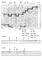
- 5a shows a top view of the one above the other arranged layers 11, 12, 13 and 14, wherein according to the invention the channels in the layers are designed and arranged such that the projection of the Channels on one level result in a grid that has a large number of equally large areas limited.
- FIG. 5a also shows predetermined points E, E and E1, E1, respectively through the formation of suitable bores through the corresponding ones Layers 11, 12, 13 and 14, which are shown symbolically circular in the drawing through which channels 111, 121, 131, 141 can be connected, whereby a Liquid channel is provided between positions E, E and E1, E1, which is shown in the drawing with arrow symbols.
- Layers 11, 12, 13 and 14 with channels 111, 121, 131 and 141 are according to the invention formed and arranged that a variety in the manner described above from positions E, E and E1, E1 using suitable holes in the layer sequence 11, 12, 13 and 14 can be connected to one another via the channels 111, 121, 131 and 141 are.
- the holes are made according to the specifications of the to be connected Positions from above or below through at least two of the four layers.
- the Layer sequence varies according to the specifications of the positions to be connected and / or at least one of the layers 11, 12, 13, 14 be omitted or replaced by another layer 11, 12, 13, 14 which then occurs several times in the layer sequence.
- a distributor plate according to the invention in corresponding positions to be connected also include only two layers 11, 12.
- Channels 111, 121, 131 and 141 in layers 11, 12, 13 and 14 can also be formed such that the channels in the top of the layers are formed to a depth which is less than the layer thickness, the Layers 11, 12, 13 and 14 can be arranged directly one above the other, whereby the top of a layer from the bottom of the overlying layer is covered, and the channels are enclosed between two layers.
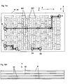
- FIG. 5b shows a first distributor plate 1 according to the invention with one above the other arranged layers 11, 12, 13 and 14, the top layer 14 also can be covered with a thin cover film D.
- Suitable are the Layers 11, 12, 13 and 14 and the cover layer D by means of heat, pressure or Adhesive bonded together so that channels 111, 121, 131 and 141 are enclosed in the distribution plate 1 in a liquid-tight and gas-tight manner.
- the cover sheet D a thickness that is sufficient inclusion of the Channels guaranteed and is also sufficiently thin to z.
- B. means Laser ablation or mechanical or thermal means in a simple way To be able to make holes through the cover layer D. Is accordingly also the depth of channels 111, 121, 131 and 141 into layers 11, 12, 13, 14 selected.
- Fig. 5c shows a modification of the distributor plate 1 of Fig. 5b, in which the channels 111, 121, 131 and 141 passing through layers 11, 12, 13 and 14 are formed, an intermediate view D. between adjacent layers is arranged, which covers the channels and also under the lowest layer a base layer G is arranged.
- the thickness of the intermediate layers D are as well as the cover layer D and base layer G are selected such that on holes in the layers D and G can be easily made can and the channels are liquid and gas tight.
- Moreover can also with corresponding specifications of the positions to be connected at least one of the intermediate layers D and preferably the intermediate layer D between the middle layers 12 and 13 are omitted, in which case the middle layers 12 and 13 bonded together at predetermined positions are.
- a distribution plate according to the invention consisting of at least two layers arranged one above the other according to the above with reference to FIGS. 5b and 5c described distribution plate is particularly suitable for providing the Drilling using laser ablation of material between two on top of each other arranged channels, since only a small amount of laser is required for this.
- This also applies to the versions described below with at least two Layers while for laser ablation of material between in one layer side by side channels an increased use of laser is required.
- FIG. 6a shows a second embodiment of the present invention, in which in a Layer 21 has a plurality of elongated channels 211 in a first direction X is formed and also a plurality of second elongated channels 212 in a second direction Y is formed.
- Channels 211 and 212 in layer 21 are suitably arranged so that a large number of equal areas each of two opposite channels 211 and two opposite Channels 212 is included, and the channels at their ends are spaced from one another in a simple manner by means of laser ablation or mechanical or thermal means a connection between a first Channel 211 or a second channel 211 or a first channel 212 and one second channel 212 or a first channel 211 and a second channel 212 can be provided.
- the direction X and the close Direction Y at an angle of 90 °. It is clear that another angle between the two directions X and Y can be advantageous, such as an angle of 60 °, the channels 211 and 211 then correspondingly are formed and arranged such that two opposite channels 211 and 212 include a diamond-shaped surface.
- Fig. 6b shows a section of an advantageous modification of Fig. 6a, the in addition to the elongated channels 211, 212 a plurality of recesses 213, suitably opposite the respective ends of the channels 211, 212 are arranged.
- This arrangement of the channels 211, 212 and Recesses 213 can be made in a simple manner by means of e.g. laser ablation Connection between at least two channels 211, 211 or 212, 212 or 211, 212 are provided by the respective partition between the channel 211, 212 and the recess 213 is removed.
- 6c shows a section of a further advantageous modification of the 6a, whose elongated channels in the first X and second Y Direction 211 and 212 are alternately arcuate.
- a distributor plate consists of the layer 21, over which a thin cover film can be arranged and can also have an additional base layer.
- the top layer and the base layer have a thickness that makes it easy to use a laser and mechanical or thermal means to drill holes in the layers and also reliably enclosing channels to 211, 212 guarantee.
- suitable holes are shown as an example positions E, E and E1, E1 and E2, E2 via channels 211, 212 are suitable connect with each other.
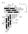
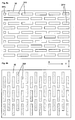
- FIG. 8a shows a plan view of a layer 31 of a third embodiment of the present invention
- FIG. 7a shows a section of the layer 31 from FIG. 8a.
- the layer 31 is rectangular, for example, and in the layer 31 first elongated channels 311 arranged substantially in a first direction X.
- the first elongated channels have a first length x1 and a first width y1 and a plurality of the first channels are in a plurality in the first direction X of rows arranged, the channels 311 in the rows with the same first distance dx1 are arranged, and wherein two adjacent rows in the first direction X against each other by a first amount of displacement dx11 are shifted and two adjacent rows in a second direction Y one have the first row spacing dy11.
- FIG. 8b shows a top view of a second layer 32 of the third embodiment of the present invention and FIG. 7b shows a section of the layer 32 from FIG. 8b.
- second elongated channels 321 are formed with a second length y2 and a second width x2 and the channels are arranged in a plurality of rows in the second direction Y, the channels being arranged one behind the other in the rows with a constant second distance dy2 , and wherein two adjacent rows in the second direction Y are displaced from one another by a second shift amount dy22 and two adjacent rows in the first direction X have a second row spacing dx22.
- the channels 311 of the first layer 31 and the channels 321 of the second layer 32 are arranged according to the invention in layers 31 and 32 such that if the layers 31 and 32 are arranged one above the other, the two ends of one first channel 311 overlap a central region of two channels 321 and at the same time, a central region of the first channel 311 an end of a third Channel 321 overlaps, and the two ends of one channel 321 in the second Layer 32 each overlap middle regions of two channels 311 in layer 31 and at the same time the central region of the channel 321 an end of a third channel 311 overlaps in layer 31.
- the first length is x1 of the first channels 311 and the second length y2 each approximately 5 times as large as the first width y1 or the second width x2.
- Fig. 9c shows a modification of the distributor plate 3 of Fig. 9b, which accordingly the distributor plate 1 shown in FIG. 5c and the distributor plate described above 1 is modified, which is why a description is also omitted here and instead, reference is made to the above passage.
- FIG. 11a shows a top view of the layers 41 and 12 arranged one above the other 42 with holes to corresponding areas E, E and E1, E1 and E2, E2 by means of of channels 421 and 411
- Figs. 11b and 11c show one distributor plate 4 according to the invention, a modification of the above with reference to FIG. 9a, 9b and 9c described distributor plate 3, and why here on another Description is omitted and instead the corresponding above Passage is referred.
- FIG. 12a shows a top view of the layers 41, 42 arranged one above the other with the channels 421 and 422, with previously determined areas E, E and E1, E1 and E2, E2 by means of suitable bores via channels 421 and 422 are connected, however, the holes for providing the connection of the Regions E, E in contrast to the bores of FIG. 11a not only connect channels arranged one above the other, but also in one Connect layers arranged one behind the other, whereby according to the invention Positioning and selection of the holes for connecting predetermined ones Areas E, E is optimized so that a smallest connection channel between the areas E, E is provided.
- Fig. 12b shows an advantageous modification of the fourth embodiment, in which one second layer 42 is arranged between two first layers 41, which are particularly is suitable, for example: to couple two similar components by the distributor plate 4 is arranged between the components.
- FIG. 13a and b show a fifth embodiment of the present invention, namely a distributor plate 5 consisting of the layers 51 arranged one above the other, 52 and 53.
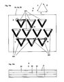
- first, second and third layers 51, 52 and 53 are respectively first, second and third elongated channels 511, 521 and 531 of predetermined length and predetermined distance substantially in a first, second and third direction X, Y and Z are formed, according to the invention two of each Directions X, Y, Z enclose an angle of 60 degrees, and one above the other arranged layers 51, 52 and 52 the ends of the channels of a layer 51, 52, 53 above or below the ends of a channel of the other two layers are arranged.
- FIG. 14 shows a distributor plate 5 of an advantageous modification of the fifth Implementation of the present invention, which also consists of a first, second and third layer 51, 52 and 53, in each of which there are first, second and third elongated channels 511, 521 and 531 of predetermined length and predetermined Distance essentially in a first, second and third direction X, Y and Z are formed, and in each case two of the directions X, Y, Z form an angle enclose of 60 °.
- a distributor plate 5 of an advantageous modification of the fifth Implementation of the present invention which also consists of a first, second and third layer 51, 52 and 53, in each of which there are first, second and third elongated channels 511, 521 and 531 of predetermined length and predetermined Distance essentially in a first, second and third direction X, Y and Z are formed, and in each case two of the directions X, Y, Z form an angle enclose of 60 °.
- Distribution plate 5 are channels 511, 521 and 531 in layers 51, 52 and 53 here advantageously designed such that when layers 51, 52 are arranged one above the other, and 53 a first end of a first channel 511, 521, 531 in a first layer 51, 52, 53 with one end of a second channel 511, 521, 531 in a second Layer 51, 52, 53 and with a central region of a third channel 511, 521, 531 overlaps in a third layer 51, 52, 53; and also a second end of the first channel 511, 521, 531 in the first layer 51, 52, 53 with one End of a fourth channel 511, 521, 531 in the third layer 51, 52, 53 and with a central region of a fifth channel 511, 521, 531 in the second layer 51, 52, 53 overlap; and also a central area of the first channel 511, 521, 531 in the first layer 51, 52, 53 with one end of a sixth and seventh channel 511, 521, 531 overlap
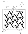
- FIG. 15 shows a section of a distributor plate 5, another advantageous one Modification of the fifth embodiment of the present invention, which also consists of a first, second and third layer 51, 52 and 53, in each of which first, second and third elongated channels 511, 521 and 531 of predetermined length and predetermined distance substantially in first, second and third Direction X, Y and Z are formed, and in each case two directions X, Y, Z enclose an angle of 60 °.
- first, second and third layer 51, 52 and 53 in each of which first, second and third elongated channels 511, 521 and 531 of predetermined length and predetermined distance substantially in first, second and third Direction X, Y and Z are formed, and in each case two directions X, Y, Z enclose an angle of 60 °.
- 13 and 14 described distributor plates 5 are the channels 511, 521 and 531 in the Layers 51, 52 and 53 here advantageously formed so curved that at layers 51, 52 and 53 arranged one above the other, the two ends of a first one Channel 511, 521, 531 in a first layer 51, 52, 53 each with a first middle area of a second channel 511, 521, 531 or third channel 511, 521, 531 overlaps in a second layer 51, 52, 53; and also a first and second middle region of the first channel 511, 521, 531 in the first layer 51, 52, 53 each with a fourth and fifth channel 511, 521, 531 in a third Layer overlaps, with the second and third channels 511, 521, 531 in the second Layer are arranged substantially opposite one another, and the fourth and fifth channel 511, 521, 531 in the third layer essentially in succession are arranged.
- the channels 511, 521, 531 in the layers 51, 52, 53 are according to the invention also arranged and designed such that two opposite channels 511, 511 and 521, 521 and 531, 531 of the first and second and third layers 51, 52, 53 essentially a circular area with a Include diameter Kd, which is essentially a row spacing Dx, Dy, Dz of channels 511, 521, 531 corresponds to the successive in the first or second or third direction X, Y, Z are arranged.
- a distributor plate 5 according to the invention described above according to FIG. 15 can be used in a particularly simple manner from above or below Positions holes are made by laser ablation, so that each a channel of a middle layer 51, 52, 53 with a channel of an upper or lower layer 51, 52, 53 is connected, as compared to a Laser ablation of walls between channels arranged in a layer particularly little energy is required. It is clear that this advantage also for the Corresponding embodiments of the present invention described above apply.
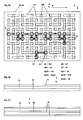
- FIG. 16a shows a plan view of an advantageously designed channel K one Layer D
- Fig. 16b shows a section through the channel K of Fig. 16a along the line A-A, the ends of which are rounded, which is fluidically special is cheap.
- 16c and d each show a channel K1 of a layer D1 and a channel K2 a layer D2, which advantageously overlap at the ends such that the end one channel K1, K2 projects slightly beyond the other channel K1, K2.
- this configuration is particularly advantageous for channels with 16a and b rounded ends and on the other hand particularly advantageous for the embodiments of the present invention described above, at which are both channels of a layer arranged one behind the other as well superimposed channels of different layers by means of suitable Holes are connectable, which ensures that holes for Connection of channels arranged one behind the other in a layer also not an unintentional connection to a channel in another layer cause.
- the present invention also provides a method using the simple and inexpensive way to produce a liquid distribution plate can be.
- This becomes at least one Layer selected and arranged appropriately and at predetermined positions suitable holes are formed in the layer or layer sequence, so that at least one liquid channel is provided.
- distribution plates consisting of one suitable combination of at least two layers arranged one above the other the above first to fifth embodiment can be advantageous, the holes to provide suitable connections of the channels from above and / or are executable below, and after having provided the holes with a thin film can be covered, and in the top and / or bottom of the Distribution plate at predetermined positions E, E1 also by means of laser ablation, etc. openings for coupling are provided.
Landscapes
- Chemical & Material Sciences (AREA)
- Engineering & Computer Science (AREA)
- General Engineering & Computer Science (AREA)
- Dispersion Chemistry (AREA)
- Health & Medical Sciences (AREA)
- Chemical Kinetics & Catalysis (AREA)
- Mechanical Engineering (AREA)
- General Health & Medical Sciences (AREA)
- Analytical Chemistry (AREA)
- Hematology (AREA)
- Clinical Laboratory Science (AREA)
- Toxicology (AREA)
- Physical Or Chemical Processes And Apparatus (AREA)
- Injection Moulding Of Plastics Or The Like (AREA)
Applications Claiming Priority (2)
| Application Number | Priority Date | Filing Date | Title |
|---|---|---|---|
| DE10055374 | 2000-11-08 | ||
| DE10055374A DE10055374B4 (de) | 2000-11-08 | 2000-11-08 | Verteilerplatte für Flüssigkeiten und Gase |
Publications (2)
| Publication Number | Publication Date |
|---|---|
| EP1205670A2 true EP1205670A2 (fr) | 2002-05-15 |
| EP1205670A3 EP1205670A3 (fr) | 2003-10-29 |
Family
ID=7662589
Family Applications (1)
| Application Number | Title | Priority Date | Filing Date |
|---|---|---|---|
| EP01126695A Withdrawn EP1205670A3 (fr) | 2000-11-08 | 2001-11-08 | Bloc distributeur pour liquides et gaz |
Country Status (2)
| Country | Link |
|---|---|
| EP (1) | EP1205670A3 (fr) |
| DE (1) | DE10055374B4 (fr) |
Cited By (3)
| Publication number | Priority date | Publication date | Assignee | Title |
|---|---|---|---|---|
| WO2011018213A1 (fr) | 2009-08-12 | 2011-02-17 | Fraunhofer-Gesellschaft zur Förderung der angewandten Forschung e.V. | Microstructuration en 3d pour la production de structures mixtes et de structures de canal en technologie multicouche destinées à être utilisées dans ou pour la construction de réacteurs |
| EP2522427A1 (fr) * | 2010-11-24 | 2012-11-14 | Fraunhofer-Gesellschaft zur Förderung der angewandten Forschung e.V. | Dispositif microfluidique et son procédé de fabrication |
| CN116808972A (zh) * | 2023-06-25 | 2023-09-29 | 陕西金禹科技发展有限公司 | 一种微通道反应器及方法 |
Family Cites Families (13)
| Publication number | Priority date | Publication date | Assignee | Title |
|---|---|---|---|---|
| CH596453A5 (en) * | 1975-07-18 | 1978-03-15 | Tschudin & Heid Ag | Pneumatic control logic element |
| GB2097282B (en) * | 1981-04-24 | 1984-06-27 | Raschig Gmbh | Parallel plate contactor |
| DE4237358A1 (de) * | 1992-11-05 | 1994-05-11 | Wiederaufarbeitung Von Kernbre | Stoffaustauschkolonne |
| AU5869494A (en) * | 1992-12-01 | 1994-06-22 | Koch Engineering Company, Inc. | Nested packing for an exchange column |
| US5958344A (en) * | 1995-11-09 | 1999-09-28 | Sarnoff Corporation | System for liquid distribution |
| DE19703779C2 (de) * | 1997-02-01 | 2003-06-05 | Karlsruhe Forschzent | Verfahren und Vorrichtung zur Herstellung eines dispersen Gemisches |
| DE19708472C2 (de) * | 1997-02-20 | 1999-02-18 | Atotech Deutschland Gmbh | Herstellverfahren für chemische Mikroreaktoren |
| US5993750A (en) * | 1997-04-11 | 1999-11-30 | Eastman Kodak Company | Integrated ceramic micro-chemical plant |
| US6156273A (en) * | 1997-05-27 | 2000-12-05 | Purdue Research Corporation | Separation columns and methods for manufacturing the improved separation columns |
| JP2001517794A (ja) * | 1997-09-19 | 2001-10-09 | アクレイラ バイオサイエンシズ,インコーポレイティド | キャピラリ電気フロー装置および方法 |
| US6074725A (en) * | 1997-12-10 | 2000-06-13 | Caliper Technologies Corp. | Fabrication of microfluidic circuits by printing techniques |
| GB9800220D0 (en) * | 1998-01-06 | 1998-03-04 | Central Research Lab Ltd | Method of forming interconnections between channels and chambers |
| US6645432B1 (en) * | 2000-05-25 | 2003-11-11 | President & Fellows Of Harvard College | Microfluidic systems including three-dimensionally arrayed channel networks |
-
2000
- 2000-11-08 DE DE10055374A patent/DE10055374B4/de not_active Expired - Fee Related
-
2001
- 2001-11-08 EP EP01126695A patent/EP1205670A3/fr not_active Withdrawn
Cited By (3)
| Publication number | Priority date | Publication date | Assignee | Title |
|---|---|---|---|---|
| WO2011018213A1 (fr) | 2009-08-12 | 2011-02-17 | Fraunhofer-Gesellschaft zur Förderung der angewandten Forschung e.V. | Microstructuration en 3d pour la production de structures mixtes et de structures de canal en technologie multicouche destinées à être utilisées dans ou pour la construction de réacteurs |
| EP2522427A1 (fr) * | 2010-11-24 | 2012-11-14 | Fraunhofer-Gesellschaft zur Förderung der angewandten Forschung e.V. | Dispositif microfluidique et son procédé de fabrication |
| CN116808972A (zh) * | 2023-06-25 | 2023-09-29 | 陕西金禹科技发展有限公司 | 一种微通道反应器及方法 |
Also Published As
| Publication number | Publication date |
|---|---|
| DE10055374B4 (de) | 2006-03-02 |
| EP1205670A3 (fr) | 2003-10-29 |
| DE10055374A1 (de) | 2002-05-29 |
Similar Documents
| Publication | Publication Date | Title |
|---|---|---|
| DE4416343C2 (de) | Statischer Mikro-Vermischer | |
| EP0879083B1 (fr) | Dispositif de melange de petites quantites de liquides | |
| DE102011078770B4 (de) | Mikrofluidische Vorrichtung, mikrofluidisches System und Verfahren zum Transport von Fluiden | |
| DE69101297T2 (de) | Plattenwärmetauscher. | |
| EP1075326B1 (fr) | Dispositif pour transporter des liquides le long de voies de guidage predeterminees | |
| DE10317263B4 (de) | Plattenwärmeübertrager mit doppelwandigen Wärmeübertragerplatten | |
| EP1674152B1 (fr) | Micromélangeur statique | |
| DE10222478A1 (de) | Verteilelement für Flüssigkeiten und Gase, Lab-on-a-Cip, Lab-on-a-Card | |
| DE102010041833B4 (de) | Mikrofluidikchip mit mehreren Zylinder-Kolben-Anordnungen | |
| DE10055374B4 (de) | Verteilerplatte für Flüssigkeiten und Gase | |
| DE102016205947B4 (de) | Reinigungsdüse mit gekrümmter Strahlführung für einen Dampf- und/oder Hochdruckreiniger | |
| EP2522427B1 (fr) | Dispositif microfluidique et son procédé de fabrication | |
| DE102019132096B3 (de) | Einrichtung zum Kühlen von Batteriezellen | |
| DE4304440B4 (de) | Ventil | |
| WO2006034666A1 (fr) | Recuperateur a microcanaux produit a partir de feuilles empilees | |
| DE102012201714A1 (de) | Verfahren zur herstellung von mikrofluidsystemen | |
| DE102022209418A1 (de) | Mikrofluidische Vorrichtung und Verfahren zu ihrem Betrieb | |
| DE102010039676B4 (de) | Kühlsystem zum Kühlen von Elektronikkomponenten | |
| EP1404447B1 (fr) | Dispositif d'analyse | |
| WO2003001215A2 (fr) | Bloc de soupapes | |
| DE102023208700A1 (de) | Mikrofluidische Vorrichtung und Verfahren zu ihrer Herstellung | |
| DE202025105706U1 (de) | Mikrofluidisches System für mikrofluidische Flusszellen | |
| DE3545559A1 (de) | Waermetauscher, insbesondere fuer eine heiz- und/oder klimaanlage eines kraftfahrzeugs | |
| DE202023101236U1 (de) | Zweiteiliger Gehäusedeckel für einen Wärmeübertrager, insbesondere eines Kraftfahrzeugs | |
| DE102024114795A1 (de) | Kanalsystem für Mikrofluidikanwendungen und Mikrofluidikverfahren |
Legal Events
| Date | Code | Title | Description |
|---|---|---|---|
| PUAI | Public reference made under article 153(3) epc to a published international application that has entered the european phase |
Free format text: ORIGINAL CODE: 0009012 |
|
| AK | Designated contracting states |
Kind code of ref document: A2 Designated state(s): AT BE CH CY DE DK ES FI FR GB GR IE IT LI LU MC NL PT SE TR |
|
| AX | Request for extension of the european patent |
Free format text: AL;LT;LV;MK;RO;SI |
|
| PUAL | Search report despatched |
Free format text: ORIGINAL CODE: 0009013 |
|
| AK | Designated contracting states |
Kind code of ref document: A3 Designated state(s): AT BE CH CY DE DK ES FI FR GB GR IE IT LI LU MC NL PT SE TR |
|
| AX | Request for extension of the european patent |
Extension state: AL LT LV MK RO SI |
|
| AKX | Designation fees paid | ||
| REG | Reference to a national code |
Ref country code: DE Ref legal event code: 8566 |
|
| STAA | Information on the status of an ep patent application or granted ep patent |
Free format text: STATUS: THE APPLICATION IS DEEMED TO BE WITHDRAWN |
|
| 18D | Application deemed to be withdrawn |
Effective date: 20040430 |