EP1205674A2 - Cheville à expansion - Google Patents
Cheville à expansion Download PDFInfo
- Publication number
- EP1205674A2 EP1205674A2 EP01124549A EP01124549A EP1205674A2 EP 1205674 A2 EP1205674 A2 EP 1205674A2 EP 01124549 A EP01124549 A EP 01124549A EP 01124549 A EP01124549 A EP 01124549A EP 1205674 A2 EP1205674 A2 EP 1205674A2
- Authority
- EP
- European Patent Office
- Prior art keywords
- expansion
- screw
- dowel
- dowel sleeve
- screw thread
- Prior art date
- Legal status (The legal status is an assumption and is not a legal conclusion. Google has not performed a legal analysis and makes no representation as to the accuracy of the status listed.)
- Granted
Links
- 238000000926 separation method Methods 0.000 claims description 25
- 238000004873 anchoring Methods 0.000 description 11
- 239000004566 building material Substances 0.000 description 5
- 230000001154 acute effect Effects 0.000 description 2
- 230000006978 adaptation Effects 0.000 description 2
- 230000006835 compression Effects 0.000 description 2
- 238000007906 compression Methods 0.000 description 2
- 239000011470 perforated brick Substances 0.000 description 2
- 229910000831 Steel Inorganic materials 0.000 description 1
- 230000015572 biosynthetic process Effects 0.000 description 1
- 238000005336 cracking Methods 0.000 description 1
- 238000006073 displacement reaction Methods 0.000 description 1
- 230000000694 effects Effects 0.000 description 1
- 239000013013 elastic material Substances 0.000 description 1
- 230000037431 insertion Effects 0.000 description 1
- 238000003780 insertion Methods 0.000 description 1
- 238000009434 installation Methods 0.000 description 1
- 239000002184 metal Substances 0.000 description 1
- 238000010079 rubber tapping Methods 0.000 description 1
- 239000010959 steel Substances 0.000 description 1
- 210000002105 tongue Anatomy 0.000 description 1
- 239000002023 wood Substances 0.000 description 1
Images
Classifications
-
- F—MECHANICAL ENGINEERING; LIGHTING; HEATING; WEAPONS; BLASTING
- F16—ENGINEERING ELEMENTS AND UNITS; GENERAL MEASURES FOR PRODUCING AND MAINTAINING EFFECTIVE FUNCTIONING OF MACHINES OR INSTALLATIONS; THERMAL INSULATION IN GENERAL
- F16B—DEVICES FOR FASTENING OR SECURING CONSTRUCTIONAL ELEMENTS OR MACHINE PARTS TOGETHER, e.g. NAILS, BOLTS, CIRCLIPS, CLAMPS, CLIPS OR WEDGES; JOINTS OR JOINTING
- F16B13/00—Dowels or other devices fastened in walls or the like by inserting them in holes made therein for that purpose
- F16B13/12—Separate metal or non-separate or non-metal dowel sleeves fastened by inserting the screw, nail or the like
- F16B13/124—Separate metal or non-separate or non-metal dowel sleeves fastened by inserting the screw, nail or the like fastened by inserting a threaded element, e.g. screw or bolt
-
- F—MECHANICAL ENGINEERING; LIGHTING; HEATING; WEAPONS; BLASTING
- F16—ENGINEERING ELEMENTS AND UNITS; GENERAL MEASURES FOR PRODUCING AND MAINTAINING EFFECTIVE FUNCTIONING OF MACHINES OR INSTALLATIONS; THERMAL INSULATION IN GENERAL
- F16B—DEVICES FOR FASTENING OR SECURING CONSTRUCTIONAL ELEMENTS OR MACHINE PARTS TOGETHER, e.g. NAILS, BOLTS, CIRCLIPS, CLAMPS, CLIPS OR WEDGES; JOINTS OR JOINTING
- F16B35/00—Screw-bolts; Stay-bolts; Screw-threaded studs; Screws; Set screws
- F16B35/04—Screw-bolts; Stay-bolts; Screw-threaded studs; Screws; Set screws with specially-shaped head or shaft in order to fix the bolt on or in an object
- F16B35/041—Specially-shaped shafts
Definitions
- the invention relates to an expansion anchor with the features of the preamble of the claim 1.
- expansion anchors are known per se. They have an anchor sleeve that passes through Screwing in a spreading screw can be expanded and thereby anchored in a borehole are.
- the expansion screw has a first screw thread, which in the Dowel sleeve of screwed expansion screw is in engagement with the dowel sleeve.
- the dowel sleeve can have longitudinal slots that divide it into spreading tongues, so that the expansion screw with lower torque into the dowel sleeve can be screwed in and the dowel sleeve can be expanded more easily. Consists of the dowel sleeve an elastic material, for example made of plastic, can also be used without it Slots are formed.
- the invention is based on the object, the anchoring force of such To increase expansion dowels.
- the anchoring force is that for pulling out the in one Borehole anchored expansion anchor necessary force.
- the Expansion screw of the expansion anchor according to the invention has a second screw thread on that with an axial distance from the first screw thread on the expansion screw is arranged.
- the second screw thread also engages with the dowel sleeve.
- the dowel sleeve a first expansion and / or predetermined separation point between the engagement areas of the two screw threads with the expansion screw screwed into the dowel sleeve on.
- the length of the second screw thread of its expansion screw and its axial Distance from the first screw thread will increase the anchoring force of the Expansion dowels reached in a borehole.
- the extension of the expansion anchor by second screw thread brings especially in building materials of low strength like Gas and aerated concrete advantages, as an expansion pressure exerted by the expansion anchor on a greater length is distributed.
- a hollow building material such as a perforated brick
- the expansion anchor according to the invention has the advantage that due to the two Screw thread of his expansion screw with a high probability a spread Area of the dowel sleeve is at least in a web of the perforated brick, see above that the expansion anchor is anchored.
- a conventional expansion anchor with only one Screw threads can cause a spread area of the Expansion dowel is essentially only in a cavity of the hollow building material and the Expansion anchor is therefore poorly anchored.
- Expansion dowel is that in a building material with different areas Strength with high probability at least a spread section of the Expansion dowel is located in a zone of high strength of the building material and thereby one good anchoring effect.
- the first expansion and / or set point separates the inventive one Expansion dowels in two completely or at least partially from each other independent expansion areas divided, which anchor the expansion anchor in a borehole.
- this reduction affects the anchoring force in an area on one side of the first expansion and / or The separation point is the anchoring force on the other side of the first expansion and / or No separation point or at least less than a no expansion and / or separation point having dowel sleeve.
- the dowel sleeve of the expansion anchor on one Embodiment of the invention on a laterally projecting collar.
- This covenant can annular disc-shaped and arranged in a radial plane or, for example also funnel-shaped for receiving a countersunk head of the expansion screw his.
- the collar overlaps an object to be fastened.
- the second expansion and / or predetermined separation point an axial distance from the engagement area of the second screw thread in the dowel sleeve with the expansion screw screwed into the dowel sleeve.
- a rear flank of the screw is second screw thread comparatively flat to the longitudinal direction of the expansion screw aligned, it runs at an angle of approximately 45 ° or less to the longitudinal direction the expansion screw.
- the second screw thread has a sawtooth shape, for example Thread profile, being a longer and at a shallower angle to Thread flank running in the longitudinal direction of the expansion screw in the screwing direction is arranged behind.
- the rear flank of the second in the screwing direction Screw thread forms an oblique or spreading surface, which occurs during an axial movement the expansion screw in the dowel sleeve further spreads the dowel sleeve.
- the in the screwing direction rear flank of the second screw thread acts in this embodiment like a cone-shaped expansion body, the one forming the expansion surface rear flank of the second screw thread helically around the expansion screw applies.
- This embodiment of the invention has the following advantage: widens Borehole in which the expansion anchor according to the invention is anchored, for example in As a result of the formation of cracks, a pull on the expansion screw causes a relative movement the expansion screw in the dowel sleeve. This relative movement of the expansion screw in the dowel sleeve causes about the comparatively flat to the longitudinal direction of the expansion screw aligned rear flank of the second expansion screw thread another Spread the dowel sleeve, i.e. spread the dowel.
- the expansion anchor according to the invention also exhibits post-expansion behavior when the borehole is widened a high anchoring force.
- the spreading behavior is determined by the one arranged between the collar of the dowel sleeve and the second screw thread second expansion and / or separation point favors because the second expansion and / or Set separation point on the dowel sleeve from an object fastened with the expansion dowel applied axial force at least reduced. This prevents a such axial force in a borehole expansion together with the Pulls the expansion screw out of the drill hole.
- the second expansion and / or separation point favors the relative movement of the expansion screw in the dowel sleeve, which increases the expansion behavior causes.
- the dowel sleeve has V-shaped slots for the Engagement of the first screw thread of the expansion screw in the area of its front End up.
- One leg of the V-shaped slots serves to engage the Screw thread, due to its oblique course, this leg is the V-shaped Slits approximately adapted to a pitch of the screw thread.
- the other Leg of the V-shaped slots allows axial expansion or compression the dowel sleeve and thus allows adaptation to threads with different Pitch.
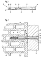
- the expansion dowel 10 has a dowel sleeve 12 made of plastic and an expansion screw 14 shown only in Figure 2.
- the dowel sleeve 12 is essentially tubular, it has a rear end a funnel-shaped, laterally projecting collar 16 for receiving a countersunk head 18 the expansion screw 14.
- the dowel sleeve 12 has two expansion and / or predetermined separation points 20, 22, which are designed as constrictions in the form of rounded, circumferential grooves are. With axial pull on the. Dowel sleeve 12 expands on its expansion and / or predetermined separation point 20, 22 and separates into two when a tearing force is exceeded or three parts.
- a first expansion and / or predetermined separation point 20 is from a longitudinal center of the Dowel sleeve 12 is arranged slightly offset in the direction of a front end of the dowel sleeve 12.
- a second expansion and / or predetermined separation point 22 is at an axial distance from The collar 16 is thus arranged in the rear area of the dowel sleeve 12.
- the longitudinal slots 24 Two extend opposite one another from the front expansion and / or predetermined separation point 20 arranged longitudinal slots 24 a bit towards the front End 19 of the dowel sleeve 12.
- the longitudinal slots 24 have one in their longitudinal center circular extension 26 on.
- the longitudinal slots 24 facilitate insertion of the Expansion screw 14 and a widening and spreading of the dowel sleeve 12 in the axial Area of the dowel sleeve 12 in which the longitudinal slots 24 are arranged.
- the dowel sleeve 12 has V-shaped slots 28, of which several are arranged one behind the other in the longitudinal direction of the dowel sleeve 12. Except the The V-shaped slots 28 visible in FIG. 1 have the dowel sleeve 12 opposite arranged V-shaped slots.
- the V-shaped slots 28 are with their tip directed to the front, their legs 30, 32 run obliquely to the rear.
- the expansion screw 14 consists of metal, in particular steel. It shows a first Screw thread 34 and a second screw thread at an axial distance behind it 36 on. Between the two screw threads 34, 36 and from the second screw thread 36 to the screw head 18, the expansion screw 14 has threadless shaft sections 38, 40 on. While the first screw thread 34 as a conventional Wood screw, triangular or pointed thread is formed the second Screw thread 36 has a sawtooth-shaped thread profile. A longer and in an acute angle, that is to say flat to a longitudinal direction of the expansion screw 14 Flank 42 is in the screwing direction of the expansion screw 14 on a rear Page arranged.
- the function of the expansion anchor 10 according to the invention is described below with reference to FIG. 2 explained in more detail:
- the dowel sleeve 12 is put through by the to be fastened Component 44 inserted into the drill hole in the masonry 46 and the expansion screw 14 is screwed into the dowel sleeve 12.
- the two screw threads 34, 36 are self-tapping, the dowel sleeve 12 therefore does not need a thread to be provided.
- the expansion screw 14 expands and spreads the dowel sleeve 12 and thereby anchors the expansion plug 10 in the drill hole in the masonry 46.
- the screw head 18 and the collar 16 of the dowel sleeve 12 overlap the one to be fastened Component 44 on the side facing away from the masonry 46 and thereby hold the component 44 on the masonry 46.
- the first expansion and / or predetermined separation point 20 in the area of a front end of the second screw thread 36 second expansion and / or setpoint separation point 22 is located between a rear end of the second screw thread 36 and the screw head 18.
- the first screw thread 34 is in an axially fixed engagement with the dowel sleeve 12 by positive locking first screw thread 34 also engages in one leg 30 of the V-shaped Slots 28 at the front end of the dowel sleeve 12.
- the other leg 32 enables an axial expansion or compression of the dowel sleeve 12 and thereby enables an adaptation to a distance between the threads of the first screw thread 34th
- the expansion screw 14 axially, for example, from the component 44 to be fastened acted upon, it moves axially in the dowel sleeve 12 to the rear.
- the rear, in Flank 42 aligned at an acute angle to the longitudinal direction of expansion screw 14 of the second screw thread 36 acts on the axial displacement of the expansion screw 14 in the dowel sleeve 12 in the manner of an expansion cone, the rear flank 42 spreads the Dowel sleeve on.
- the expansion dowel 10 according to the invention thus has a post-expansion behavior so that it has a high anchoring force even when expanding the borehole having.
- the second expansion and / or set point 42 favors the necessary for the re-spreading Relative movement of the expansion screw 14 in the dowel sleeve 12, since it is a Axial movement of the rear part of the dowel sleeve 12 relative to the front part of the Allows dowel sleeve 12.
- the first expansion and / or set separation point 20 an axial movement of the part of the dowel sleeve 12 in front of it relative to the part behind it. Due to the first expansion and / or setpoint separation point 20 the expansion plug 10 according to the invention is arranged similarly to two in a row and in particular expansion anchors connected to one another by the expansion screw 14 look at.
Landscapes
- Engineering & Computer Science (AREA)
- General Engineering & Computer Science (AREA)
- Mechanical Engineering (AREA)
- Dowels (AREA)
- Joining Of Building Structures In Genera (AREA)
- Piles And Underground Anchors (AREA)
- Pharmaceuticals Containing Other Organic And Inorganic Compounds (AREA)
- Materials For Medical Uses (AREA)
Applications Claiming Priority (2)
| Application Number | Priority Date | Filing Date | Title |
|---|---|---|---|
| DE10055866 | 2000-11-10 | ||
| DE10055866A DE10055866A1 (de) | 2000-11-10 | 2000-11-10 | Spreizdübel |
Publications (3)
| Publication Number | Publication Date |
|---|---|
| EP1205674A2 true EP1205674A2 (fr) | 2002-05-15 |
| EP1205674A3 EP1205674A3 (fr) | 2002-11-06 |
| EP1205674B1 EP1205674B1 (fr) | 2004-12-08 |
Family
ID=7662899
Family Applications (1)
| Application Number | Title | Priority Date | Filing Date |
|---|---|---|---|
| EP01124549A Expired - Lifetime EP1205674B1 (fr) | 2000-11-10 | 2001-10-13 | Cheville à expansion |
Country Status (6)
| Country | Link |
|---|---|
| EP (1) | EP1205674B1 (fr) |
| AT (1) | ATE284491T1 (fr) |
| CZ (1) | CZ20014041A3 (fr) |
| DE (2) | DE10055866A1 (fr) |
| HU (1) | HUP0104829A3 (fr) |
| PL (1) | PL350590A1 (fr) |
Cited By (2)
| Publication number | Priority date | Publication date | Assignee | Title |
|---|---|---|---|---|
| EP2037129A1 (fr) * | 2007-09-14 | 2009-03-18 | Allfa Dübel GmbH | Cheville de tige longue |
| EP2302226A1 (fr) * | 2009-09-29 | 2011-03-30 | fischerwerke GmbH & Co. KG | Cheville double et procédé de montage d'espacement |
Families Citing this family (2)
| Publication number | Priority date | Publication date | Assignee | Title |
|---|---|---|---|---|
| DE102005018485A1 (de) * | 2005-04-21 | 2006-10-26 | Fischerwerke Artur Fischer Gmbh & Co. Kg | Dübel zur Verankerung in Vollbaustoffen |
| DE102020102294A1 (de) | 2020-01-30 | 2021-08-05 | Dehn Se + Co Kg | Montagesystem |
Family Cites Families (8)
| Publication number | Priority date | Publication date | Assignee | Title |
|---|---|---|---|---|
| DE2607338C2 (de) * | 1976-02-23 | 1986-01-09 | Hilti Ag, Schaan | Schlagdübel mit Spreizhülse und Spreizelement |
| DE2947752A1 (de) * | 1979-11-27 | 1981-07-23 | M.Meisinger KG, 8890 Aichach | Kunststoffduebel |
| GB2091368B (en) * | 1981-01-21 | 1984-09-19 | Tucker Fasteners Ltd | Drive anchor |
| DE3317798A1 (de) * | 1983-05-17 | 1984-11-22 | Bernd 4352 Herten Gräwe | Befestigungselement fuer bauteile an mit loechern versehenen baukoerpern o. dgl. |
| DE3429585A1 (de) * | 1984-08-10 | 1986-02-20 | Alfons 5758 Fröndenberg Knoche | Aus einem kunststoffspreizduebel und einer befestigungsschraube bestehender befestigungssatz |
| DE9310356U1 (de) * | 1993-07-12 | 1993-09-23 | Mea Meisinger Stahl und Kunststoff GmbH, 86551 Aichach | Spreizduebel |
| DE19936927A1 (de) * | 1999-02-06 | 2000-08-10 | Fischer Artur Werke Gmbh | Kunststoffdübel |
| DE19915474A1 (de) * | 1999-04-06 | 2000-10-12 | Fischer Artur Werke Gmbh | Spreizdübel |
-
2000
- 2000-11-10 DE DE10055866A patent/DE10055866A1/de not_active Withdrawn
-
2001
- 2001-10-13 DE DE2001504755 patent/DE50104755D1/de not_active Expired - Fee Related
- 2001-10-13 EP EP01124549A patent/EP1205674B1/fr not_active Expired - Lifetime
- 2001-10-13 AT AT01124549T patent/ATE284491T1/de not_active IP Right Cessation
- 2001-11-08 PL PL01350590A patent/PL350590A1/xx not_active IP Right Cessation
- 2001-11-09 HU HU0104829A patent/HUP0104829A3/hu unknown
- 2001-11-09 CZ CZ20014041A patent/CZ20014041A3/cs unknown
Non-Patent Citations (1)
| Title |
|---|
| None |
Cited By (2)
| Publication number | Priority date | Publication date | Assignee | Title |
|---|---|---|---|---|
| EP2037129A1 (fr) * | 2007-09-14 | 2009-03-18 | Allfa Dübel GmbH | Cheville de tige longue |
| EP2302226A1 (fr) * | 2009-09-29 | 2011-03-30 | fischerwerke GmbH & Co. KG | Cheville double et procédé de montage d'espacement |
Also Published As
| Publication number | Publication date |
|---|---|
| HUP0104829A3 (en) | 2003-04-28 |
| ATE284491T1 (de) | 2004-12-15 |
| CZ20014041A3 (cs) | 2002-06-12 |
| EP1205674B1 (fr) | 2004-12-08 |
| HU0104829D0 (en) | 2002-01-28 |
| DE10055866A1 (de) | 2002-05-29 |
| EP1205674A3 (fr) | 2002-11-06 |
| PL350590A1 (en) | 2002-05-20 |
| HUP0104829A2 (en) | 2002-10-28 |
| DE50104755D1 (de) | 2005-01-13 |
Similar Documents
| Publication | Publication Date | Title |
|---|---|---|
| EP2309138B1 (fr) | Piton à expansion | |
| EP3047161B1 (fr) | Ancre extensible | |
| EP0308619B1 (fr) | Chéville à expansion | |
| DE3124823A1 (de) | Spreizduebel | |
| EP1183475A1 (fr) | Cheville destinee a etre fixee a des materiaux de construction creux et solides | |
| EP0723085B1 (fr) | Cheville à expansion | |
| WO2001066962A1 (fr) | Cheville a expansion | |
| EP1412644A1 (fr) | Cheville a expansion | |
| EP0381678B1 (fr) | Cheville a contre-depouille | |
| EP1205674B1 (fr) | Cheville à expansion | |
| DE4403894A1 (de) | Spreizdübel | |
| EP1872020B1 (fr) | Cheville pour ancrage dans des materiaux de construction en dur | |
| EP1026413B1 (fr) | Cheville en matière plastique et vis d'expansion | |
| EP0874167A1 (fr) | Cheville d'expansion | |
| EP0503677A2 (fr) | Ancre pour des charges lourdes | |
| EP0388694A1 (fr) | Cheville expansible | |
| EP0737817B1 (fr) | Dispositif de fixation avec élément d'expansion | |
| DE102004052184A1 (de) | Nageldübel | |
| EP0508096B1 (fr) | Procédé de fabrication d'une cheville d'expansion en métal | |
| EP0913592B1 (fr) | Cheville à percussion | |
| DE19720033A1 (de) | Spreizanker zum Befestigen an einem Hohlkammern aufweisenden Bauwerk | |
| WO2001061198A1 (fr) | Cheville a expansion | |
| EP0893610B1 (fr) | Cheville d'expansion | |
| DE9310356U1 (de) | Spreizduebel | |
| DE20106520U1 (de) | Dübel |
Legal Events
| Date | Code | Title | Description |
|---|---|---|---|
| PUAI | Public reference made under article 153(3) epc to a published international application that has entered the european phase |
Free format text: ORIGINAL CODE: 0009012 |
|
| AK | Designated contracting states |
Kind code of ref document: A2 Designated state(s): AT BE CH CY DE DK ES FI FR GB GR IE IT LI LU MC NL PT SE TR |
|
| AX | Request for extension of the european patent |
Free format text: AL;LT;LV;MK;RO;SI |
|
| PUAL | Search report despatched |
Free format text: ORIGINAL CODE: 0009013 |
|
| AK | Designated contracting states |
Kind code of ref document: A3 Designated state(s): AT BE CH CY DE DK ES FI FR GB GR IE IT LI LU MC NL PT SE TR |
|
| AX | Request for extension of the european patent |
Free format text: AL;LT;LV;MK;RO;SI |
|
| RIC1 | Information provided on ipc code assigned before grant |
Free format text: 7F 16B 13/06 A, 7F 16B 35/04 B, 7F 16B 5/02 B, 7F 16B 13/12 B |
|
| 17P | Request for examination filed |
Effective date: 20030214 |
|
| AKX | Designation fees paid |
Designated state(s): AT BE CH CY DE DK ES FI FR GB GR IE IT LI LU MC NL PT SE TR |
|
| 17Q | First examination report despatched |
Effective date: 20031106 |
|
| GRAP | Despatch of communication of intention to grant a patent |
Free format text: ORIGINAL CODE: EPIDOSNIGR1 |
|
| GRAS | Grant fee paid |
Free format text: ORIGINAL CODE: EPIDOSNIGR3 |
|
| GRAA | (expected) grant |
Free format text: ORIGINAL CODE: 0009210 |
|
| AK | Designated contracting states |
Kind code of ref document: B1 Designated state(s): AT BE CH CY DE DK ES FI FR GB GR IE IT LI LU MC NL PT SE TR |
|
| PG25 | Lapsed in a contracting state [announced via postgrant information from national office to epo] |
Ref country code: TR Free format text: LAPSE BECAUSE OF FAILURE TO SUBMIT A TRANSLATION OF THE DESCRIPTION OR TO PAY THE FEE WITHIN THE PRESCRIBED TIME-LIMIT Effective date: 20041208 Ref country code: NL Free format text: LAPSE BECAUSE OF FAILURE TO SUBMIT A TRANSLATION OF THE DESCRIPTION OR TO PAY THE FEE WITHIN THE PRESCRIBED TIME-LIMIT Effective date: 20041208 Ref country code: IT Free format text: LAPSE BECAUSE OF FAILURE TO SUBMIT A TRANSLATION OF THE DESCRIPTION OR TO PAY THE FEE WITHIN THE PRESCRIBED TIME-LIMIT;WARNING: LAPSES OF ITALIAN PATENTS WITH EFFECTIVE DATE BEFORE 2007 MAY HAVE OCCURRED AT ANY TIME BEFORE 2007. THE CORRECT EFFECTIVE DATE MAY BE DIFFERENT FROM THE ONE RECORDED. Effective date: 20041208 Ref country code: IE Free format text: LAPSE BECAUSE OF FAILURE TO SUBMIT A TRANSLATION OF THE DESCRIPTION OR TO PAY THE FEE WITHIN THE PRESCRIBED TIME-LIMIT Effective date: 20041208 Ref country code: GB Free format text: LAPSE BECAUSE OF FAILURE TO SUBMIT A TRANSLATION OF THE DESCRIPTION OR TO PAY THE FEE WITHIN THE PRESCRIBED TIME-LIMIT Effective date: 20041208 Ref country code: FR Free format text: LAPSE BECAUSE OF FAILURE TO SUBMIT A TRANSLATION OF THE DESCRIPTION OR TO PAY THE FEE WITHIN THE PRESCRIBED TIME-LIMIT Effective date: 20041208 Ref country code: FI Free format text: LAPSE BECAUSE OF FAILURE TO SUBMIT A TRANSLATION OF THE DESCRIPTION OR TO PAY THE FEE WITHIN THE PRESCRIBED TIME-LIMIT Effective date: 20041208 |
|
| REG | Reference to a national code |
Ref country code: GB Ref legal event code: FG4D Free format text: NOT ENGLISH |
|
| REG | Reference to a national code |
Ref country code: CH Ref legal event code: EP |
|
| REG | Reference to a national code |
Ref country code: IE Ref legal event code: FG4D Free format text: GERMAN |
|
| REF | Corresponds to: |
Ref document number: 50104755 Country of ref document: DE Date of ref document: 20050113 Kind code of ref document: P |
|
| PG25 | Lapsed in a contracting state [announced via postgrant information from national office to epo] |
Ref country code: SE Free format text: LAPSE BECAUSE OF FAILURE TO SUBMIT A TRANSLATION OF THE DESCRIPTION OR TO PAY THE FEE WITHIN THE PRESCRIBED TIME-LIMIT Effective date: 20050308 Ref country code: GR Free format text: LAPSE BECAUSE OF FAILURE TO SUBMIT A TRANSLATION OF THE DESCRIPTION OR TO PAY THE FEE WITHIN THE PRESCRIBED TIME-LIMIT Effective date: 20050308 Ref country code: DK Free format text: LAPSE BECAUSE OF FAILURE TO SUBMIT A TRANSLATION OF THE DESCRIPTION OR TO PAY THE FEE WITHIN THE PRESCRIBED TIME-LIMIT Effective date: 20050308 |
|
| PG25 | Lapsed in a contracting state [announced via postgrant information from national office to epo] |
Ref country code: ES Free format text: LAPSE BECAUSE OF FAILURE TO SUBMIT A TRANSLATION OF THE DESCRIPTION OR TO PAY THE FEE WITHIN THE PRESCRIBED TIME-LIMIT Effective date: 20050319 |
|
| NLV1 | Nl: lapsed or annulled due to failure to fulfill the requirements of art. 29p and 29m of the patents act | ||
| GBV | Gb: ep patent (uk) treated as always having been void in accordance with gb section 77(7)/1977 [no translation filed] |
Effective date: 20041208 |
|
| REG | Reference to a national code |
Ref country code: IE Ref legal event code: FD4D |
|
| PG25 | Lapsed in a contracting state [announced via postgrant information from national office to epo] |
Ref country code: CY Free format text: LAPSE BECAUSE OF FAILURE TO SUBMIT A TRANSLATION OF THE DESCRIPTION OR TO PAY THE FEE WITHIN THE PRESCRIBED TIME-LIMIT Effective date: 20051013 Ref country code: AT Free format text: LAPSE BECAUSE OF NON-PAYMENT OF DUE FEES Effective date: 20051013 |
|
| PLBE | No opposition filed within time limit |
Free format text: ORIGINAL CODE: 0009261 |
|
| STAA | Information on the status of an ep patent application or granted ep patent |
Free format text: STATUS: NO OPPOSITION FILED WITHIN TIME LIMIT |
|
| PG25 | Lapsed in a contracting state [announced via postgrant information from national office to epo] |
Ref country code: MC Free format text: LAPSE BECAUSE OF NON-PAYMENT OF DUE FEES Effective date: 20051031 Ref country code: LU Free format text: LAPSE BECAUSE OF NON-PAYMENT OF DUE FEES Effective date: 20051031 Ref country code: LI Free format text: LAPSE BECAUSE OF NON-PAYMENT OF DUE FEES Effective date: 20051031 Ref country code: CH Free format text: LAPSE BECAUSE OF NON-PAYMENT OF DUE FEES Effective date: 20051031 Ref country code: BE Free format text: LAPSE BECAUSE OF NON-PAYMENT OF DUE FEES Effective date: 20051031 |
|
| 26N | No opposition filed |
Effective date: 20050909 |
|
| EN | Fr: translation not filed | ||
| PGFP | Annual fee paid to national office [announced via postgrant information from national office to epo] |
Ref country code: DE Payment date: 20060523 Year of fee payment: 6 |
|
| REG | Reference to a national code |
Ref country code: CH Ref legal event code: PL |
|
| BERE | Be: lapsed |
Owner name: FISCHERWERKE ARTUR *FISCHER G.M.B.H. & CO. K.G. Effective date: 20051031 |
|
| PG25 | Lapsed in a contracting state [announced via postgrant information from national office to epo] |
Ref country code: PT Free format text: LAPSE BECAUSE OF NON-PAYMENT OF DUE FEES Effective date: 20050508 |
|
| PG25 | Lapsed in a contracting state [announced via postgrant information from national office to epo] |
Ref country code: DE Free format text: LAPSE BECAUSE OF NON-PAYMENT OF DUE FEES Effective date: 20080501 |