EP1205690A2 - Steuerung für ein automatisiertes, manuelles Getriebe - Google Patents
Steuerung für ein automatisiertes, manuelles Getriebe Download PDFInfo
- Publication number
- EP1205690A2 EP1205690A2 EP01126780A EP01126780A EP1205690A2 EP 1205690 A2 EP1205690 A2 EP 1205690A2 EP 01126780 A EP01126780 A EP 01126780A EP 01126780 A EP01126780 A EP 01126780A EP 1205690 A2 EP1205690 A2 EP 1205690A2
- Authority
- EP
- European Patent Office
- Prior art keywords
- hydraulic pressure
- gear
- transmission
- clutch
- working fluid
- Prior art date
- Legal status (The legal status is an assumption and is not a legal conclusion. Google has not performed a legal analysis and makes no representation as to the accuracy of the status listed.)
- Granted
Links
Images

Classifications
-
- F—MECHANICAL ENGINEERING; LIGHTING; HEATING; WEAPONS; BLASTING
- F16—ENGINEERING ELEMENTS AND UNITS; GENERAL MEASURES FOR PRODUCING AND MAINTAINING EFFECTIVE FUNCTIONING OF MACHINES OR INSTALLATIONS; THERMAL INSULATION IN GENERAL
- F16H—GEARING
- F16H61/00—Control functions within control units of change-speed- or reversing-gearings for conveying rotary motion ; Control of exclusively fluid gearing, friction gearing, gearings with endless flexible members or other particular types of gearing
- F16H61/0021—Generation or control of line pressure
- F16H61/0025—Supply of control fluid; Pumps therefor
- F16H61/0031—Supply of control fluid; Pumps therefor using auxiliary pumps, e.g. pump driven by a different power source than the engine
-
- F—MECHANICAL ENGINEERING; LIGHTING; HEATING; WEAPONS; BLASTING
- F16—ENGINEERING ELEMENTS AND UNITS; GENERAL MEASURES FOR PRODUCING AND MAINTAINING EFFECTIVE FUNCTIONING OF MACHINES OR INSTALLATIONS; THERMAL INSULATION IN GENERAL
- F16H—GEARING
- F16H61/00—Control functions within control units of change-speed- or reversing-gearings for conveying rotary motion ; Control of exclusively fluid gearing, friction gearing, gearings with endless flexible members or other particular types of gearing
- F16H61/12—Detecting malfunction or potential malfunction, e.g. fail safe ; Circumventing or fixing failures
-
- F—MECHANICAL ENGINEERING; LIGHTING; HEATING; WEAPONS; BLASTING
- F16—ENGINEERING ELEMENTS AND UNITS; GENERAL MEASURES FOR PRODUCING AND MAINTAINING EFFECTIVE FUNCTIONING OF MACHINES OR INSTALLATIONS; THERMAL INSULATION IN GENERAL
- F16H—GEARING
- F16H61/00—Control functions within control units of change-speed- or reversing-gearings for conveying rotary motion ; Control of exclusively fluid gearing, friction gearing, gearings with endless flexible members or other particular types of gearing
- F16H61/0021—Generation or control of line pressure
- F16H61/0025—Supply of control fluid; Pumps therefor
- F16H2061/0034—Accumulators for fluid pressure supply; Control thereof
-
- F—MECHANICAL ENGINEERING; LIGHTING; HEATING; WEAPONS; BLASTING
- F16—ENGINEERING ELEMENTS AND UNITS; GENERAL MEASURES FOR PRODUCING AND MAINTAINING EFFECTIVE FUNCTIONING OF MACHINES OR INSTALLATIONS; THERMAL INSULATION IN GENERAL
- F16H—GEARING
- F16H61/00—Control functions within control units of change-speed- or reversing-gearings for conveying rotary motion ; Control of exclusively fluid gearing, friction gearing, gearings with endless flexible members or other particular types of gearing
- F16H61/12—Detecting malfunction or potential malfunction, e.g. fail safe ; Circumventing or fixing failures
- F16H2061/1208—Detecting malfunction or potential malfunction, e.g. fail safe ; Circumventing or fixing failures with diagnostic check cycles; Monitoring of failures
-
- F—MECHANICAL ENGINEERING; LIGHTING; HEATING; WEAPONS; BLASTING
- F16—ENGINEERING ELEMENTS AND UNITS; GENERAL MEASURES FOR PRODUCING AND MAINTAINING EFFECTIVE FUNCTIONING OF MACHINES OR INSTALLATIONS; THERMAL INSULATION IN GENERAL
- F16H—GEARING
- F16H61/00—Control functions within control units of change-speed- or reversing-gearings for conveying rotary motion ; Control of exclusively fluid gearing, friction gearing, gearings with endless flexible members or other particular types of gearing
- F16H61/12—Detecting malfunction or potential malfunction, e.g. fail safe ; Circumventing or fixing failures
- F16H2061/1232—Bringing the control into a predefined state, e.g. giving priority to particular actuators or gear ratios
-
- F—MECHANICAL ENGINEERING; LIGHTING; HEATING; WEAPONS; BLASTING
- F16—ENGINEERING ELEMENTS AND UNITS; GENERAL MEASURES FOR PRODUCING AND MAINTAINING EFFECTIVE FUNCTIONING OF MACHINES OR INSTALLATIONS; THERMAL INSULATION IN GENERAL
- F16H—GEARING
- F16H61/00—Control functions within control units of change-speed- or reversing-gearings for conveying rotary motion ; Control of exclusively fluid gearing, friction gearing, gearings with endless flexible members or other particular types of gearing
- F16H61/12—Detecting malfunction or potential malfunction, e.g. fail safe ; Circumventing or fixing failures
- F16H2061/1256—Detecting malfunction or potential malfunction, e.g. fail safe ; Circumventing or fixing failures characterised by the parts or units where malfunctioning was assumed or detected
- F16H2061/126—Detecting malfunction or potential malfunction, e.g. fail safe ; Circumventing or fixing failures characterised by the parts or units where malfunctioning was assumed or detected the failing part is the controller
- F16H2061/1264—Hydraulic parts of the controller, e.g. a sticking valve or clogged channel
-
- F—MECHANICAL ENGINEERING; LIGHTING; HEATING; WEAPONS; BLASTING
- F16—ENGINEERING ELEMENTS AND UNITS; GENERAL MEASURES FOR PRODUCING AND MAINTAINING EFFECTIVE FUNCTIONING OF MACHINES OR INSTALLATIONS; THERMAL INSULATION IN GENERAL
- F16H—GEARING
- F16H61/00—Control functions within control units of change-speed- or reversing-gearings for conveying rotary motion ; Control of exclusively fluid gearing, friction gearing, gearings with endless flexible members or other particular types of gearing
- F16H61/12—Detecting malfunction or potential malfunction, e.g. fail safe ; Circumventing or fixing failures
- F16H2061/1256—Detecting malfunction or potential malfunction, e.g. fail safe ; Circumventing or fixing failures characterised by the parts or units where malfunctioning was assumed or detected
- F16H2061/126—Detecting malfunction or potential malfunction, e.g. fail safe ; Circumventing or fixing failures characterised by the parts or units where malfunctioning was assumed or detected the failing part is the controller
- F16H2061/1268—Electric parts of the controller, e.g. a defect solenoid, wiring or microprocessor
-
- F—MECHANICAL ENGINEERING; LIGHTING; HEATING; WEAPONS; BLASTING
- F16—ENGINEERING ELEMENTS AND UNITS; GENERAL MEASURES FOR PRODUCING AND MAINTAINING EFFECTIVE FUNCTIONING OF MACHINES OR INSTALLATIONS; THERMAL INSULATION IN GENERAL
- F16H—GEARING
- F16H61/00—Control functions within control units of change-speed- or reversing-gearings for conveying rotary motion ; Control of exclusively fluid gearing, friction gearing, gearings with endless flexible members or other particular types of gearing
- F16H61/16—Inhibiting or initiating shift during unfavourable conditions , e.g. preventing forward-reverse shift at high vehicle speed, preventing engine overspeed
- F16H2061/166—Preventing or initiating shifts for preventing stall or overspeed of engine
-
- F—MECHANICAL ENGINEERING; LIGHTING; HEATING; WEAPONS; BLASTING
- F16—ENGINEERING ELEMENTS AND UNITS; GENERAL MEASURES FOR PRODUCING AND MAINTAINING EFFECTIVE FUNCTIONING OF MACHINES OR INSTALLATIONS; THERMAL INSULATION IN GENERAL
- F16H—GEARING
- F16H61/00—Control functions within control units of change-speed- or reversing-gearings for conveying rotary motion ; Control of exclusively fluid gearing, friction gearing, gearings with endless flexible members or other particular types of gearing
- F16H61/26—Generation or transmission of movements for final actuating mechanisms
- F16H61/28—Generation or transmission of movements for final actuating mechanisms with at least one movement of the final actuating mechanism being caused by a non-mechanical force, e.g. power-assisted
- F16H61/30—Hydraulic or pneumatic motors or related fluid control means therefor
- F16H2061/305—Accumulators for fluid supply to the servo motors, or control thereof
-
- F—MECHANICAL ENGINEERING; LIGHTING; HEATING; WEAPONS; BLASTING
- F16—ENGINEERING ELEMENTS AND UNITS; GENERAL MEASURES FOR PRODUCING AND MAINTAINING EFFECTIVE FUNCTIONING OF MACHINES OR INSTALLATIONS; THERMAL INSULATION IN GENERAL
- F16H—GEARING
- F16H61/00—Control functions within control units of change-speed- or reversing-gearings for conveying rotary motion ; Control of exclusively fluid gearing, friction gearing, gearings with endless flexible members or other particular types of gearing
- F16H61/16—Inhibiting or initiating shift during unfavourable conditions , e.g. preventing forward-reverse shift at high vehicle speed, preventing engine overspeed
-
- F—MECHANICAL ENGINEERING; LIGHTING; HEATING; WEAPONS; BLASTING
- F16—ENGINEERING ELEMENTS AND UNITS; GENERAL MEASURES FOR PRODUCING AND MAINTAINING EFFECTIVE FUNCTIONING OF MACHINES OR INSTALLATIONS; THERMAL INSULATION IN GENERAL
- F16H—GEARING
- F16H61/00—Control functions within control units of change-speed- or reversing-gearings for conveying rotary motion ; Control of exclusively fluid gearing, friction gearing, gearings with endless flexible members or other particular types of gearing
- F16H61/68—Control functions within control units of change-speed- or reversing-gearings for conveying rotary motion ; Control of exclusively fluid gearing, friction gearing, gearings with endless flexible members or other particular types of gearing specially adapted for stepped gearings
- F16H61/682—Control functions within control units of change-speed- or reversing-gearings for conveying rotary motion ; Control of exclusively fluid gearing, friction gearing, gearings with endless flexible members or other particular types of gearing specially adapted for stepped gearings with interruption of drive
-
- Y—GENERAL TAGGING OF NEW TECHNOLOGICAL DEVELOPMENTS; GENERAL TAGGING OF CROSS-SECTIONAL TECHNOLOGIES SPANNING OVER SEVERAL SECTIONS OF THE IPC; TECHNICAL SUBJECTS COVERED BY FORMER USPC CROSS-REFERENCE ART COLLECTIONS [XRACs] AND DIGESTS
- Y10—TECHNICAL SUBJECTS COVERED BY FORMER USPC
- Y10T—TECHNICAL SUBJECTS COVERED BY FORMER US CLASSIFICATION
- Y10T74/00—Machine element or mechanism
- Y10T74/19—Gearing
- Y10T74/19219—Interchangeably locked
- Y10T74/19251—Control mechanism
Definitions
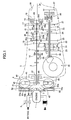
- Fig. 1 is a skeleton view showing a control apparatus of a transmission in accordance with the embodiment of the present invention.
- the synchromesh mechanism 31 includes a synchronous hub 31a fixed to the output shaft 4 and a synchronous sleeve 31b always engaging therewith.
- a transmission gear ratio is set to a first speed gear range
- a spline 22a integrally formed in the second speed driven gear 22 it is set to a second speed gear range.
- the input clutch 51 is structured so as to be hydraulically controlled independently of a circulating fluid within the torque converter 6. Since the rotation of the turbine runner 45 is transmitted to the input shaft 3 via the input clutch 51, and on the other hand, the lockup clutch 54 is connected to the clutch drum 52, the rotation of the crankshaft 7 is directly transmitted to the input shaft 3 when engaging the lockup clutch 54. Thus, the power from the crankshaft 7 is transmitted to the input shaft 3 via the torque converter 6 or the lockup clutch 54.
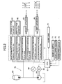
- Signals are inputted to the ECU 67 from an inhibitor switch 71, a vehicle speed sensor 75, and an engine speed sensor 76.
- an alarm lamp 77 for informing the driver that a trouble has occurred in a hydraulic pressure system 70 is connected to the ECU 67.
- the ECU 67 detects a position of the select lever based on the signals from the inhibitor switch 71, a current vehicle speed from the vehicle speed sensor, and an engine speed from the engine speed sensor 76, so that the driving condition of the vehicle can be detected based on the above detected data. According to the detected driving condition, the ECU 67 outputs driving signals to the electric motor 65 if necessary, in which each actuator 61-64 is controlled to be driven by the hydraulic pressure system 70.
- a part of the working fluid supplied from the oil pump 66 is stored in an accumulator (pressure storing means) 69, as shown in Fig. 2.
- a sealed container of the accumulator 69 is filled with a gas such as a nitrogen, and then the gas is compressed by pressing the working fluid into the accumulator, so that a pressure energy of the working fluid can be converted into a pressure energy of the gas to be stored. That is, the line pressure is stored in the accumulator 69, thereby stabilizing the line pressure.
- the select actuator 63 is controlled by the electromagnetic switching valves VA3, VA4, while the shift actuator 64 is controlled by the electromagnetic pressure control valve, because a two-position switching operation (a selecting operation) in the A direction can be sufficiently executed by simply pressing by a large operating force until striking against a dead stop, while a three-position switching operation (a shift operation) in the B direction requires a synchronism by the synchronous mechanism. Since an excessive operating force causes an abrasion of a synchronous ring thereof, it is desired to control the operating force itself. Further, since the shift operating force in the B direction is larger than the select operating force in the A direction, loud noises occur at a time of being brought into contact with the dead stop, so that a countermeasure against operating noises is required.
- the shift change operation is controlled by the ECU 67.
- a neutral position is selected by the select lever provided within the vehicle compartment in a state where the engine is driven, both of the lockup clutch 54 and the input clutch 51 are set in a released state.
- the ECU 67 controls the electromagnetic pressure control valve VA2 so as to supply the hydraulic pressure to the input clutch 51, so that the input clutch 51 is in a contact state due to the hydraulic pressure.
- the synchronous sleeve 31b is engaged with the spline 21a by the shift actuator 64 so as to achieve that the first speed transmission gear train becomes the power transmitting state and thereafter the hydraulic pressure is applied so as to engage the input clutch 51.
- the power of the engine 1 is transmitted to the input shaft 3 via the torque converter 6 and the input clutch 51, so that the vehicle can travel.
- the power is amplified due to a torque amplifying effect of the torque converter 6 so as to be transmitted to the input shaft 3.
- the electronic control throttle valve 2 is opened, and thus, according to an increase of the vehicle speed, the up-shift gear change operation is executed. Also, the down-shift gear change operation is executed in accordance with a reduction of the vehicle speed or a kick-down operation of deeply depressing the accelerator pedal. At this time, the shift change is automatically executed in accordance with a gear change pattern previously programmed in the ECU 67.
- step S2 in which the ECU 67 checks as to whether the electric motor 65 and oil pump 66 is normally working. That is, a rising rate of hydraulic pressure is detected from a rising value of hydraulic pressure within a predetermined time based on a detected value by the pressure sensor 68, which is compared with a predetermined value previously set. Normally, the rising rate of hydraulic pressure is constant and never less than the predetermined value if the electric motor 65 and oil pump 66 is normally working. However, in the case that, for example, there occurs malfunction in the electric motor 65 or leakage of the working fluid, the rising rate of hydraulic pressure is extremely lowered.
- the step goes to a step S3, in which the ECU 67 determines that there occurred a malfunction in the hydraulic pressure system 70 including the electric motor 65.
- the rising rate is over the predetermined value, it is determined that the hydraulic pressure system 70 is normally working, and thus the step terminates.
- the bypass clutch 18 is provided at the input shaft 3, but may be provided at the output shaft 4, or at the intermediate shaft independently located in parallel to the both.
- the bypass gears 17 and 27 are set to the gear ratio corresponding to the third speed gear range, but may be a gear ratio corresponding to a fourth or fifth speed gear range.
- the switching mechanism of the transmission gear ratio the synchromesh mechanisms 31 to 33 are used, but the structure is not limited to them, and a dog clutch switching or the like may be employed.
Landscapes
- Engineering & Computer Science (AREA)
- General Engineering & Computer Science (AREA)
- Mechanical Engineering (AREA)
- Control Of Transmission Device (AREA)
- Gear-Shifting Mechanisms (AREA)
Applications Claiming Priority (2)
| Application Number | Priority Date | Filing Date | Title |
|---|---|---|---|
| JP2000344900A JP2002147597A (ja) | 2000-11-13 | 2000-11-13 | 車両用自動変速機の制御装置 |
| JP2000344900 | 2000-11-13 |
Publications (3)
| Publication Number | Publication Date |
|---|---|
| EP1205690A2 true EP1205690A2 (de) | 2002-05-15 |
| EP1205690A3 EP1205690A3 (de) | 2004-06-16 |
| EP1205690B1 EP1205690B1 (de) | 2007-01-03 |
Family
ID=18819028
Family Applications (1)
| Application Number | Title | Priority Date | Filing Date |
|---|---|---|---|
| EP01126780A Expired - Lifetime EP1205690B1 (de) | 2000-11-13 | 2001-11-09 | Steuerung für ein automatisiertes, manuelles Getriebe |
Country Status (4)
| Country | Link |
|---|---|
| US (1) | US6546826B2 (de) |
| EP (1) | EP1205690B1 (de) |
| JP (1) | JP2002147597A (de) |
| DE (1) | DE60125690T2 (de) |
Cited By (3)
| Publication number | Priority date | Publication date | Assignee | Title |
|---|---|---|---|---|
| WO2003048614A1 (de) * | 2001-12-04 | 2003-06-12 | Zf Friedrichshafen Ag | Verfahren zur ansteuerung einer druckversorgungseinrichtung in einem hydraulikkreis |
| EP1860349A1 (de) * | 2006-05-23 | 2007-11-28 | Magneti Marelli Powertrain S.p.A. | Verfahren zur Steuerung einer Druckmittelvorrichtung zum Schalten eines servobetätigten Schaltgetriebes |
| CN108006097A (zh) * | 2016-10-27 | 2018-05-08 | 丰田自动车株式会社 | 车辆用变速器的控制装置 |
Families Citing this family (22)
| Publication number | Priority date | Publication date | Assignee | Title |
|---|---|---|---|---|
| JP3502058B2 (ja) * | 2001-04-16 | 2004-03-02 | 富士重工業株式会社 | 自動変速機 |
| DE10146958A1 (de) * | 2001-09-24 | 2003-04-17 | Zahnradfabrik Friedrichshafen | Modul für Aktuatoren in einem Fahrzeug |
| JP4323132B2 (ja) * | 2002-03-15 | 2009-09-02 | 株式会社日立製作所 | 自動車の制御方法,自動車の制御装置,変速機,変速機の制御装置および車両システム |
| JP2007120586A (ja) * | 2005-10-26 | 2007-05-17 | Toyota Motor Corp | 車両用自動変速機の制御装置 |
| DE102006016412A1 (de) * | 2006-04-07 | 2007-10-11 | Zf Friedrichshafen Ag | Verfahren und Vorrichtung zur Steuerung eines fluidbetätigten Steuersystems |
| EP1944532B1 (de) * | 2007-01-12 | 2009-08-26 | Magneti Marelli S.p.A. | Hydraulisch servogesteuerte Übertragung für ein mit einer internen Verbrennungsmaschine ausgerüsteten Strassenfahrzeug |
| JP4483871B2 (ja) * | 2007-02-05 | 2010-06-16 | トヨタ自動車株式会社 | 動力伝達装置の制御装置およびその制御方法 |
| JP4447613B2 (ja) * | 2007-02-08 | 2010-04-07 | トヨタ自動車株式会社 | ハイブリッド車両の駆動力制御装置 |
| JP5029394B2 (ja) * | 2008-01-31 | 2012-09-19 | トヨタ自動車株式会社 | 自動変速機の制御装置、制御方法およびその方法をコンピュータに実現させるプログラムならびにそのプログラムを記録した記録媒体 |
| US9764726B2 (en) | 2009-01-02 | 2017-09-19 | Ford Global Technologies, Llc | Methods and systems for assisted direct start control |
| US8328687B2 (en) | 2010-07-09 | 2012-12-11 | Ford Global Technologies, Llc | Method for controlling an engine that may be automatically stopped |
| US8414456B2 (en) | 2010-07-09 | 2013-04-09 | Ford Global Technologies, Llc | Method for starting an engine |
| US8864623B2 (en) | 2010-07-09 | 2014-10-21 | Ford Global Technologies, Llc | Method for controlling a transmission coupled to an engine that may be automatically stopped |
| KR101481267B1 (ko) * | 2013-05-20 | 2015-01-09 | 현대자동차주식회사 | 차량의 페일 세이프 장치 및 그 제어방법 |
| JP6501354B2 (ja) * | 2015-05-12 | 2019-04-17 | 株式会社エフ・シー・シー | 車両用動力伝達システム |
| WO2017074308A1 (en) * | 2015-10-27 | 2017-05-04 | Borgwarner Inc. | Automated manual transmission clutch with accumulator |
| ITUB20161185A1 (it) * | 2016-03-01 | 2017-09-01 | Magneti Marelli Spa | Procedimento per verificare un'eventuale riduzione del livello di olio in un sistema di attuazione idraulico, in particolare un sistema di attuazione idraulico per trasmissione di veicolo. |
| DE102016214370B3 (de) * | 2016-08-03 | 2017-12-14 | Audi Ag | Hydrauliksystem für ein Automatikgetriebe eines Kraftfahrzeugs |
| US10316963B2 (en) * | 2017-04-25 | 2019-06-11 | GM Global Technology Operations LLC | Pressure sensor rationality diagnostic for a dual clutch transmission |
| JP6443526B2 (ja) * | 2017-12-04 | 2018-12-26 | スズキ株式会社 | 車両用自動変速機 |
| KR102663169B1 (ko) * | 2018-12-27 | 2024-05-03 | 현대트랜시스 주식회사 | 차량의 dct 유압제어 회로 및 그 제어방법 |
| JP7070717B2 (ja) * | 2019-01-30 | 2022-05-18 | 株式会社アイシン | 車両用駆動装置 |
Family Cites Families (9)
| Publication number | Priority date | Publication date | Assignee | Title |
|---|---|---|---|---|
| DE2145667A1 (de) * | 1971-09-13 | 1973-03-22 | Bosch Gmbh Robert | Gangschaltvorrichtung |
| US3766793A (en) * | 1972-08-15 | 1973-10-23 | Gen Motors Corp | Transmission shift controls |
| JPS552807A (en) * | 1978-06-19 | 1980-01-10 | Nissan Motor Co Ltd | Parallel axial gear transmission |
| US4858501A (en) * | 1988-08-11 | 1989-08-22 | General Motors Corporation | Shift inhibit valve for a transmission control |
| DE4015290A1 (de) * | 1989-05-16 | 1990-11-22 | Zahnradfabrik Friedrichshafen | Elektropneumatisches schaltsystem |
| DE19605722C2 (de) * | 1996-02-16 | 1998-07-09 | Mannesmann Sachs Ag | Einrichtung zur Funktionsüberprüfung einer elektrisch steuerbaren Aktuatoranordnung |
| NL1002987C2 (nl) * | 1996-05-02 | 1997-11-06 | Applied Power Inc | Inrichting voor het kiezen en inschakelen van de versnelling van een mechanische versnellingsbak. |
| JP2002147601A (ja) * | 2000-11-13 | 2002-05-22 | Fuji Heavy Ind Ltd | 車両用自動変速機の制御装置 |
| FR2829822B1 (fr) * | 2001-09-14 | 2003-12-05 | Renault | Procede de commande des electrovannes d'une transmission automatisee |
-
2000
- 2000-11-13 JP JP2000344900A patent/JP2002147597A/ja active Pending
-
2001
- 2001-11-09 EP EP01126780A patent/EP1205690B1/de not_active Expired - Lifetime
- 2001-11-09 US US09/986,749 patent/US6546826B2/en not_active Expired - Fee Related
- 2001-11-09 DE DE60125690T patent/DE60125690T2/de not_active Expired - Fee Related
Cited By (5)
| Publication number | Priority date | Publication date | Assignee | Title |
|---|---|---|---|---|
| WO2003048614A1 (de) * | 2001-12-04 | 2003-06-12 | Zf Friedrichshafen Ag | Verfahren zur ansteuerung einer druckversorgungseinrichtung in einem hydraulikkreis |
| US7073328B2 (en) | 2001-12-04 | 2006-07-11 | Zf Friedrichshafen Ag | Method for controlling a pressure supply device in a hydraulic circuit |
| EP1860349A1 (de) * | 2006-05-23 | 2007-11-28 | Magneti Marelli Powertrain S.p.A. | Verfahren zur Steuerung einer Druckmittelvorrichtung zum Schalten eines servobetätigten Schaltgetriebes |
| CN108006097A (zh) * | 2016-10-27 | 2018-05-08 | 丰田自动车株式会社 | 车辆用变速器的控制装置 |
| CN108006097B (zh) * | 2016-10-27 | 2019-10-15 | 丰田自动车株式会社 | 车辆用变速器的控制装置 |
Also Published As
| Publication number | Publication date |
|---|---|
| US20020056332A1 (en) | 2002-05-16 |
| EP1205690A3 (de) | 2004-06-16 |
| DE60125690D1 (de) | 2007-02-15 |
| US6546826B2 (en) | 2003-04-15 |
| EP1205690B1 (de) | 2007-01-03 |
| JP2002147597A (ja) | 2002-05-22 |
| DE60125690T2 (de) | 2007-10-11 |
Similar Documents
| Publication | Publication Date | Title |
|---|---|---|
| EP1205690B1 (de) | Steuerung für ein automatisiertes, manuelles Getriebe | |
| KR960000593B1 (ko) | 차량용자동변속기의 변속제어장치 및 방법 | |
| US9032824B2 (en) | Control device for dual clutch transmission and control method for dual clutch transmission | |
| US7402123B2 (en) | Automatic transmission control method and system having fail-safe function | |
| EP2221512B1 (de) | Hydraulische Steuervorrichtung eines Automatikgetriebes | |
| EP2063151B1 (de) | Schaltungssteuerungsvorrichtung mit abnormaler Zustand eines automatisierten manuellen Getriebes | |
| US6865965B2 (en) | Hydraulic control system of automated manual transmission | |
| JPH0849763A (ja) | 自動機械式変速装置の制御方法及び装置 | |
| US20030056612A1 (en) | Transmission with automatic clutch | |
| US6732601B2 (en) | Control apparatus of an automated manual transmission | |
| JP4515592B2 (ja) | 車両の自動変速装置 | |
| US6551213B2 (en) | Control apparatus of vehicular automated manual transmission | |
| JP4493934B2 (ja) | 自動変速機の変速制御装置 | |
| US7128686B2 (en) | Method and apparatus for synchronized PTO control in a motor vehicle powertrain | |
| US6712725B2 (en) | Hydraulic control apparatus of an automatic transmission | |
| JP4284820B2 (ja) | 車両の自動変速装置 | |
| EP1462682A2 (de) | Schaltsteuereinrichtung eines automatisierten Fahrzeuggetriebes | |
| JP2002310278A (ja) | 自動変速機 | |
| JPH09112679A (ja) | 自動変速機用油圧制御装置 | |
| JP3142171B2 (ja) | 車両用自動変速機の変速制御方法 | |
| JP3214759B2 (ja) | 車両用自動変速機の制御装置 | |
| JP3005338B2 (ja) | 自動変速機の制御装置 | |
| JPH05203022A (ja) | 自動変速機の油圧制御装置 | |
| JP2002340111A (ja) | 副変速機付き変速装置 | |
| JPS62171554A (ja) | 自動変速機の変速制御装置 |
Legal Events
| Date | Code | Title | Description |
|---|---|---|---|
| PUAI | Public reference made under article 153(3) epc to a published international application that has entered the european phase |
Free format text: ORIGINAL CODE: 0009012 |
|
| AK | Designated contracting states |
Kind code of ref document: A2 Designated state(s): AT BE CH CY DE DK ES FI FR GB GR IE IT LI LU MC NL PT SE TR |
|
| AX | Request for extension of the european patent |
Free format text: AL;LT;LV;MK;RO;SI |
|
| PUAL | Search report despatched |
Free format text: ORIGINAL CODE: 0009013 |
|
| AK | Designated contracting states |
Kind code of ref document: A3 Designated state(s): AT BE CH CY DE DK ES FI FR GB GR IE IT LI LU MC NL PT SE TR |
|
| AX | Request for extension of the european patent |
Extension state: AL LT LV MK RO SI |
|
| 17P | Request for examination filed |
Effective date: 20041004 |
|
| 17Q | First examination report despatched |
Effective date: 20050110 |
|
| AKX | Designation fees paid |
Designated state(s): DE GB |
|
| RBV | Designated contracting states (corrected) |
Designated state(s): DE GB |
|
| GRAP | Despatch of communication of intention to grant a patent |
Free format text: ORIGINAL CODE: EPIDOSNIGR1 |
|
| GRAS | Grant fee paid |
Free format text: ORIGINAL CODE: EPIDOSNIGR3 |
|
| GRAA | (expected) grant |
Free format text: ORIGINAL CODE: 0009210 |
|
| AK | Designated contracting states |
Kind code of ref document: B1 Designated state(s): DE GB |
|
| REG | Reference to a national code |
Ref country code: GB Ref legal event code: FG4D |
|
| REF | Corresponds to: |
Ref document number: 60125690 Country of ref document: DE Date of ref document: 20070215 Kind code of ref document: P |
|
| PLBE | No opposition filed within time limit |
Free format text: ORIGINAL CODE: 0009261 |
|
| STAA | Information on the status of an ep patent application or granted ep patent |
Free format text: STATUS: NO OPPOSITION FILED WITHIN TIME LIMIT |
|
| 26N | No opposition filed |
Effective date: 20071005 |
|
| PGFP | Annual fee paid to national office [announced via postgrant information from national office to epo] |
Ref country code: DE Payment date: 20081107 Year of fee payment: 8 |
|
| PGFP | Annual fee paid to national office [announced via postgrant information from national office to epo] |
Ref country code: GB Payment date: 20081105 Year of fee payment: 8 |
|
| GBPC | Gb: european patent ceased through non-payment of renewal fee |
Effective date: 20091109 |
|
| PG25 | Lapsed in a contracting state [announced via postgrant information from national office to epo] |
Ref country code: DE Free format text: LAPSE BECAUSE OF NON-PAYMENT OF DUE FEES Effective date: 20100601 |
|
| PG25 | Lapsed in a contracting state [announced via postgrant information from national office to epo] |
Ref country code: GB Free format text: LAPSE BECAUSE OF NON-PAYMENT OF DUE FEES Effective date: 20091109 |