EP1205692A2 - Dispositif de changement de vitesses pour transmission multivitesses - Google Patents
Dispositif de changement de vitesses pour transmission multivitesses Download PDFInfo
- Publication number
- EP1205692A2 EP1205692A2 EP20010123012 EP01123012A EP1205692A2 EP 1205692 A2 EP1205692 A2 EP 1205692A2 EP 20010123012 EP20010123012 EP 20010123012 EP 01123012 A EP01123012 A EP 01123012A EP 1205692 A2 EP1205692 A2 EP 1205692A2
- Authority
- EP
- European Patent Office
- Prior art keywords
- finger
- shift
- switching
- receiving opening
- spring
- Prior art date
- Legal status (The legal status is an assumption and is not a legal conclusion. Google has not performed a legal analysis and makes no representation as to the accuracy of the status listed.)
- Withdrawn
Links
- 230000005540 biological transmission Effects 0.000 claims description 11
- 230000004308 accommodation Effects 0.000 abstract 1
- 238000013016 damping Methods 0.000 description 2
- 238000006073 displacement reaction Methods 0.000 description 2
- 238000003754 machining Methods 0.000 description 2
- 238000006243 chemical reaction Methods 0.000 description 1
- 230000001419 dependent effect Effects 0.000 description 1
- 238000011161 development Methods 0.000 description 1
- 230000018109 developmental process Effects 0.000 description 1
- 210000003746 feather Anatomy 0.000 description 1
- 238000000034 method Methods 0.000 description 1
- 230000001902 propagating effect Effects 0.000 description 1
- 230000001960 triggered effect Effects 0.000 description 1
- 230000036642 wellbeing Effects 0.000 description 1
Images


Classifications
-
- F—MECHANICAL ENGINEERING; LIGHTING; HEATING; WEAPONS; BLASTING
- F16—ENGINEERING ELEMENTS AND UNITS; GENERAL MEASURES FOR PRODUCING AND MAINTAINING EFFECTIVE FUNCTIONING OF MACHINES OR INSTALLATIONS; THERMAL INSULATION IN GENERAL
- F16H—GEARING
- F16H63/00—Control outputs from the control unit to change-speed- or reversing-gearings for conveying rotary motion or to other devices than the final output mechanism
- F16H63/02—Final output mechanisms therefor; Actuating means for the final output mechanisms
- F16H63/08—Multiple final output mechanisms being moved by a single common final actuating mechanism
- F16H63/20—Multiple final output mechanisms being moved by a single common final actuating mechanism with preselection and subsequent movement of each final output mechanism by movement of the final actuating mechanism in two different ways, e.g. guided by a shift gate
-
- F—MECHANICAL ENGINEERING; LIGHTING; HEATING; WEAPONS; BLASTING
- F16—ENGINEERING ELEMENTS AND UNITS; GENERAL MEASURES FOR PRODUCING AND MAINTAINING EFFECTIVE FUNCTIONING OF MACHINES OR INSTALLATIONS; THERMAL INSULATION IN GENERAL
- F16H—GEARING
- F16H63/00—Control outputs from the control unit to change-speed- or reversing-gearings for conveying rotary motion or to other devices than the final output mechanism
- F16H63/02—Final output mechanisms therefor; Actuating means for the final output mechanisms
- F16H63/30—Constructional features of the final output mechanisms
-
- F—MECHANICAL ENGINEERING; LIGHTING; HEATING; WEAPONS; BLASTING
- F16—ENGINEERING ELEMENTS AND UNITS; GENERAL MEASURES FOR PRODUCING AND MAINTAINING EFFECTIVE FUNCTIONING OF MACHINES OR INSTALLATIONS; THERMAL INSULATION IN GENERAL
- F16H—GEARING
- F16H63/00—Control outputs from the control unit to change-speed- or reversing-gearings for conveying rotary motion or to other devices than the final output mechanism
- F16H63/02—Final output mechanisms therefor; Actuating means for the final output mechanisms
- F16H63/30—Constructional features of the final output mechanisms
- F16H2063/3083—Shift finger arrangements, e.g. shape or attachment of shift fingers
-
- F—MECHANICAL ENGINEERING; LIGHTING; HEATING; WEAPONS; BLASTING
- F16—ENGINEERING ELEMENTS AND UNITS; GENERAL MEASURES FOR PRODUCING AND MAINTAINING EFFECTIVE FUNCTIONING OF MACHINES OR INSTALLATIONS; THERMAL INSULATION IN GENERAL
- F16H—GEARING
- F16H59/00—Control inputs to control units of change-speed- or reversing-gearings for conveying rotary motion
- F16H59/02—Selector apparatus
- F16H59/0208—Selector apparatus with means for suppression of vibrations or reduction of noise
Definitions
- the invention relates to a switching device for a multi-speed gear change transmission of a motor vehicle in which a longitudinally displaceable and / or shift shaft accommodated pivotably in a transmission housing via a switching finger connected to it in a receiving opening of a Driver engages a longitudinally displaceable shift rod, on one Shift fork is arranged, which is operatively connected to a sliding sleeve stands.
- Such switching devices for gear change transmissions have been around since known for a long time.
- a device is for example in the DE 195 80 804 C1 described.
- a gearbox of a manual transmission is a shift shaft in bearings in the direction of its axis and in The circumferential direction is arranged so as to be pivotable about this axis.
- On the Switch shaft is attached to a locking sleeve.
- the locking sleeve with corresponding locking recesses provided engage in the locking balls of a ball lock.
- Ball lock is fixed in the gear housing.
- the shift finger the locking sleeve in turn engages in a receiving opening of a longitudinally displaceable Shift rod so that with the help of attached to the shift rod Shift forks over sliding sleeves individual gear wheels of the transmission are switchable.
- the disadvantage here is that resonance-dependent starting from the drive train Vibrations via the contact of the shift finger and the opening of the Carrier are transferred to the selector shaft.
- the powertrain is there to be considered as a vibratory system, its individual components have different masses, stiffness and damping.
- Such vibrations which can be undesirable distortion noises, Rattling, rattling or vibrations on the shaft lever in the interior of a Making the motor vehicle noticeable reduces comfort.
- Under comfort is the subjective well-being of a vehicle occupant in the sense of the invention be in a motor vehicle that is essentially caused by vibrations affected by frequency, effective value, duration, direction and A distinction must be made between the place of exposure.
- the invention is therefore based on the object, the comfort of a switching device for a multi-speed gear change transmission.
- this task is performed according to the characterizing part of Claim 1 solved in that the switching finger in the switched state the receiving opening of the driver rests on both sides, the shift finger at least one sprung produced by an elastic spring element Has contact.
- This measure according to the invention ensures that vibrations, which is noticeable by the undesirable noises described above make, be damped, taking damping in a known manner the conversion of periodically supplied energy into another form of energy understand is.
- These noises are caused by torsional vibrations of the gear train caused.
- synchronizer rings, sliding sleeves, shift forks can also be excited to vibrate.
- the shift rod is in the switched state by tensioning the involved Partner eliminated the game and thus the chain of forwarding the propagating vibrations interrupted at this point, d. H. an improved one Achieved comfort of the circuit. Vibrations, for example from the sliding sleeve to the shift fork can now no noise generate more through a constantly changing contact on the shift finger.
- the switching finger has a fixed contact and a spring-loaded contact or two spring-loaded contacts.
- the spring element should be arranged in the area of the shift finger, with the most varied design variants for the design of the spring element are conceivable:
- the shift finger with at least one continuous Be bore provided in the two spaced apart by a spring balls displaceable against each other are arranged, being in the outer Area of the shift finger the diameter of the bore is less than that The diameter of the balls is like this and the hole inside the shift finger is arranged that in the switched state one of the balls on a wall of the receiving opening.
- the switch finger is in contact in the receiving opening by a fixed contact and by a sprung Contact realized.
- the Shift finger with two through holes arranged one above the other be provided in which two spaced apart from each other by a spring Slidable balls are arranged, being in the outer area of the shift finger the diameter of the holes is less than the diameter the balls and the holes are arranged within the shift finger are that in the switched state one of the balls on one wall of the receiving opening.
- both are investment points of the shift finger in the receiving opening realized by spring-loaded contacts.
- the spring element can be U-shaped, wherein a base part plugged onto the shift finger, at least the shift finger partially surrounding legs connects, one of which in the switched Condition on a wall of the receiving opening.
- one contact point is a fixed contact and the other a sprung one Contact is.
- the shift finger should be provided with a circumferential groove into which an O-ring is inserted.
- the spring element is to be connected to the shift shaft Switch sleeve be plugged in and from a part of the locking sleeve enclosing semicircular base and two angled Legs exist, one of which in the switched state on one Neighboring area of the receiving opening is present.
- This type of spring arrangement ensures that there is contact of the shift finger in the receiving opening is given, which in turn is on the one hand by a Fixed contact and on the other hand is realized by a spring-loaded contact.
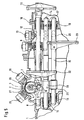
- the manual transmission shown in Figure 5 exists essentially from the transmission housing 1, in which the selector shaft 2 in In the direction of its axis 3 longitudinally displaceable and pivotable about its axis 3 is held over invisible bearings.
- the control shaft 2 is with the locking sleeve 4 connected, the shift finger 5 in the receiving opening 6 of the driver 7 engages.
- the driver 7 is in turn firmly connected to the shift rod 8, the roller-mounted longitudinal guides 9, 10 in the gear housing 1 is stored.
- the shift fork 11 is attached, the via a sliding sleeve, not shown, with the also not shown switchable gears is in operative connection.
- the shift rod is for fixation 8 provided with the locking contour 12, in which the ball lock 13 engages.
- shift rods 14 and 15 are on further longitudinal guides 16, 17, 18 and 19 mounted in the gear housing 1, these also others Have drivers 20, 21 and shift forks 22, 23 and locking contours 24, 25.
- the locking sleeve 4 connected to the control shaft 2 has on its outer surface also two locking contours 26 and 27, in which the ball locks 28 and 29 engage, so that the selector shaft 2 in the switched state secured both in the longitudinal and in the circumferential direction against displacement is.
- the shift finger 5 shown in FIGS. 1a, 1b is with the spring element 44 provided that from the through hole 30, the two therein through the Spring 32 is held at a distance from each other balls 31.
- the hole 30 is designed so that it unites on both sides in the outer area Has diameter that is slightly smaller than the diameter of the balls 31, so that they are prevented from falling out of the shift finger 5. This can be done, for example, by caulking.
- the shift finger 5 on both sides bears against the walls 33 and 34 of the receiving opening 6, so that the fixed contact 35 is formed on the left-hand side and the spring-loaded contact 36 is formed on the right-hand side is. If the driver 7 now vibrates via the drive train triggered, this is damped by the spring-loaded contact 36.
- the shift finger 5 shown in FIGS. 2a and 2b differs from 1a, 1b in that it has a spring element 45, which consists of two through bores 30 arranged one above the other consists in which in turn spaced apart by the spring 32 Balls 31 are arranged so that in the switched state according to FIG 2b on the left-hand and right-hand wall 33, 34, each with a spring Contact 36 results.
- a spring element 45 which consists of two through bores 30 arranged one above the other consists in which in turn spaced apart by the spring 32 Balls 31 are arranged so that in the switched state according to FIG 2b on the left-hand and right-hand wall 33, 34, each with a spring Contact 36 results.
- the shift finger 5 is in the receiving opening 6 held by the spring element 37 attached to this, the base part 38 has two angled legs 39 which at least the shift finger 5 partially enclose.
- the system is in the switched state according to FIG. 3b realized by shift finger 5 in the receiving opening 6 so that again the fixed contact 35 on the left and the spring-loaded contact 36 on the right is formed.
Landscapes
- Engineering & Computer Science (AREA)
- General Engineering & Computer Science (AREA)
- Mechanical Engineering (AREA)
- Gear-Shifting Mechanisms (AREA)
Applications Claiming Priority (2)
| Application Number | Priority Date | Filing Date | Title |
|---|---|---|---|
| DE10055593 | 2000-11-09 | ||
| DE2000155593 DE10055593A1 (de) | 2000-11-09 | 2000-11-09 | Schalteinrichtung für ein mehrgängiges Zahnräderwechselgetriebe eines Kraftfahrzeuges |
Publications (1)
| Publication Number | Publication Date |
|---|---|
| EP1205692A2 true EP1205692A2 (fr) | 2002-05-15 |
Family
ID=7662724
Family Applications (1)
| Application Number | Title | Priority Date | Filing Date |
|---|---|---|---|
| EP20010123012 Withdrawn EP1205692A2 (fr) | 2000-11-09 | 2001-09-26 | Dispositif de changement de vitesses pour transmission multivitesses |
Country Status (2)
| Country | Link |
|---|---|
| EP (1) | EP1205692A2 (fr) |
| DE (1) | DE10055593A1 (fr) |
Cited By (4)
| Publication number | Priority date | Publication date | Assignee | Title |
|---|---|---|---|---|
| EP2116746A1 (fr) * | 2008-05-07 | 2009-11-11 | GM Global Technology Operations, Inc. | Mécanisme de contrôle de déplacement |
| WO2013029721A1 (fr) * | 2011-08-26 | 2013-03-07 | Hoerbiger Automotive Komfortsysteme Gmbh | Système d'assistance au changement de rapports de transmission |
| GB2509972A (en) * | 2013-01-21 | 2014-07-23 | Gm Global Tech Operations Inc | Shift mechanism with shift finger having a damping member |
| FR3064329A1 (fr) * | 2017-03-27 | 2018-09-28 | Peugeot Citroen Automobiles Sa | Boite de vitesses a vibrations reduites |
Families Citing this family (7)
| Publication number | Priority date | Publication date | Assignee | Title |
|---|---|---|---|---|
| EP1626209B1 (fr) | 2004-08-09 | 2012-10-10 | Getrag Ford Transmissions GmbH | Commande interne des boîtes de vitesses avec dispositif de billage et de verrouillage |
| FR2887949B1 (fr) * | 2005-07-04 | 2008-07-18 | Renault Sas | Billage embarque sur doigt de passage |
| FR2888303A1 (fr) * | 2005-07-05 | 2007-01-12 | Renault Sas | Dispositif de billage et boite de vitesses a arbres paralleles |
| FR2897917B1 (fr) | 2006-02-24 | 2008-06-06 | Peugeot Citroen Automobiles Sa | Boite de vitesse de vehicule automobile |
| DE102006023527A1 (de) * | 2006-05-19 | 2007-11-22 | Zf Friedrichshafen Ag | Schaltvorrichtung für ein Handschaltgetriebe eines Kraftfahrzeuges |
| DE102011110611A1 (de) * | 2011-08-16 | 2013-02-21 | GM Global Technology Operations LLC (n. d. Gesetzen des Staates Delaware) | Übertragungsglied für das Schaltgetriebe eines Kraftfahrzeuges, insbesondere Schaltgabel |
| DE102015220466B3 (de) * | 2015-10-21 | 2017-01-05 | Bayerische Motoren Werke Aktiengesellschaft | Einrichtung zum Schalten eines Getriebes |
Citations (1)
| Publication number | Priority date | Publication date | Assignee | Title |
|---|---|---|---|---|
| DE19580804C1 (de) | 1994-07-27 | 1999-09-30 | Schaeffler Waelzlager Ohg | Rastierhülse für die Sicherung von Verstellpositionen eines Stellelementes, insbesondere eines Schaltgestänges für Kraftfahrzeuge |
Family Cites Families (2)
| Publication number | Priority date | Publication date | Assignee | Title |
|---|---|---|---|---|
| JPS57139830A (en) * | 1981-02-20 | 1982-08-30 | Nissan Motor Co Ltd | Operation mechanism of manual transmission |
| DE4223409A1 (de) * | 1992-07-16 | 1992-11-26 | Zahnradfabrik Friedrichshafen | Gangschalteinrichtung fuer wechselgetriebe |
-
2000
- 2000-11-09 DE DE2000155593 patent/DE10055593A1/de not_active Withdrawn
-
2001
- 2001-09-26 EP EP20010123012 patent/EP1205692A2/fr not_active Withdrawn
Patent Citations (1)
| Publication number | Priority date | Publication date | Assignee | Title |
|---|---|---|---|---|
| DE19580804C1 (de) | 1994-07-27 | 1999-09-30 | Schaeffler Waelzlager Ohg | Rastierhülse für die Sicherung von Verstellpositionen eines Stellelementes, insbesondere eines Schaltgestänges für Kraftfahrzeuge |
Cited By (7)
| Publication number | Priority date | Publication date | Assignee | Title |
|---|---|---|---|---|
| EP2116746A1 (fr) * | 2008-05-07 | 2009-11-11 | GM Global Technology Operations, Inc. | Mécanisme de contrôle de déplacement |
| WO2013029721A1 (fr) * | 2011-08-26 | 2013-03-07 | Hoerbiger Automotive Komfortsysteme Gmbh | Système d'assistance au changement de rapports de transmission |
| CN103765057A (zh) * | 2011-08-26 | 2014-04-30 | 贺尔碧格汽车舒适系统有限责任公司 | 换挡力支持装置 |
| CN103765057B (zh) * | 2011-08-26 | 2016-11-02 | 贺尔碧格汽车舒适系统有限责任公司 | 换档力支持装置 |
| GB2509972A (en) * | 2013-01-21 | 2014-07-23 | Gm Global Tech Operations Inc | Shift mechanism with shift finger having a damping member |
| FR3064329A1 (fr) * | 2017-03-27 | 2018-09-28 | Peugeot Citroen Automobiles Sa | Boite de vitesses a vibrations reduites |
| WO2018178529A1 (fr) | 2017-03-27 | 2018-10-04 | Psa Automobiles Sa | Boîte de vitesses à vibrations réduites |
Also Published As
| Publication number | Publication date |
|---|---|
| DE10055593A1 (de) | 2002-05-29 |
Similar Documents
| Publication | Publication Date | Title |
|---|---|---|
| DE102004022413B4 (de) | Doppelkupplungsgetriebe | |
| DE19741633C1 (de) | Schaltvorrichtung für ein Wechselgetriebe von Kraftfahrzeugen | |
| DE10316163A1 (de) | Mehrstufiges Schaltgetriebe für eine Brennkraftmaschine | |
| DE1550701A1 (de) | Drehzahl-UEbersetzungsgetriebe | |
| EP1205692A2 (fr) | Dispositif de changement de vitesses pour transmission multivitesses | |
| DE19702541B4 (de) | Zweiteiliges Gangrad für Schaltgetriebe | |
| DE1904663B2 (de) | Mechanische schalteinrichtung fuer ein zahnraederwechselgetriebe mit zusatzgetriebe | |
| DE3808025A1 (de) | Schalthebel | |
| DE2460769B2 (de) | Lagerung für einen Schalthebel in einem Kraftfahrzeug | |
| WO2009033932A2 (fr) | Dispositif de changement de vitesse | |
| DE19624857A1 (de) | Kurzbauendes Sechsganggetriebe | |
| EP0399106B1 (fr) | Arbre de commande de changement de vitesse avec amortisseur de vibrations | |
| DE3634174A1 (de) | Vorrichtung zum daempfen von schwingungen in einer getriebeschaltvorrichtung fuer fahrzeuge | |
| DE69007749T2 (de) | Gangschaltungsvorrichtung. | |
| EP2614918B1 (fr) | Procédé de fabrication d'un tube commutateur avec perçage d'ouvertures par laser | |
| EP0681124A2 (fr) | Dispositif amortisseur de vibrations dans un mécanisme de changement de vitesses d'une transmission de véhicule | |
| DE102004036498A1 (de) | Einrichtung zur Rastierung und Verriegelung für Mehrfachkupplungsgetriebe | |
| DE102011001162A1 (de) | Übertragungselement zum Betätigen eines Schaltelementes und Schaltvorrichtung | |
| DE102005062248A1 (de) | Schaltanordnung mit einer Schaltgabel | |
| DE4407540B4 (de) | Steuereinrichtung für ein Getriebe | |
| DE102013224741A1 (de) | Manuell betätigbare Schalteinrichtung eines Zahnräderwechselgetriebes | |
| DE102019132883A1 (de) | Kettenschaltung | |
| DE102008053142B4 (de) | Schaltbetätigungsvorrichtung | |
| DE102009056299A1 (de) | Schaltelement für ein Schaltgetriebe | |
| DE19941795C1 (de) | Automatikschaltgriff mit Druckmechanismus |
Legal Events
| Date | Code | Title | Description |
|---|---|---|---|
| PUAI | Public reference made under article 153(3) epc to a published international application that has entered the european phase |
Free format text: ORIGINAL CODE: 0009012 |
|
| 17P | Request for examination filed |
Effective date: 20010926 |
|
| AK | Designated contracting states |
Kind code of ref document: A2 Designated state(s): AT BE CH CY DE DK ES FI FR GB GR IE IT LI LU MC NL PT SE TR |
|
| AX | Request for extension of the european patent |
Free format text: AL;LT;LV;MK;RO;SI |
|
| RAP1 | Party data changed (applicant data changed or rights of an application transferred) |
Owner name: INA-SCHAEFFLER KG |
|
| STAA | Information on the status of an ep patent application or granted ep patent |
Free format text: STATUS: THE APPLICATION IS DEEMED TO BE WITHDRAWN |
|
| 18D | Application deemed to be withdrawn |
Effective date: 20040401 |
|
| P01 | Opt-out of the competence of the unified patent court (upc) registered |
Effective date: 20230522 |