EP1205725A2 - Echangeur de chaleur - Google Patents
Echangeur de chaleur Download PDFInfo
- Publication number
- EP1205725A2 EP1205725A2 EP01660204A EP01660204A EP1205725A2 EP 1205725 A2 EP1205725 A2 EP 1205725A2 EP 01660204 A EP01660204 A EP 01660204A EP 01660204 A EP01660204 A EP 01660204A EP 1205725 A2 EP1205725 A2 EP 1205725A2
- Authority
- EP
- European Patent Office
- Prior art keywords
- heat exchanger
- heat transfer
- wires
- heat
- twisted
- Prior art date
- Legal status (The legal status is an assumption and is not a legal conclusion. Google has not performed a legal analysis and makes no representation as to the accuracy of the status listed.)
- Withdrawn
Links
Images


Classifications
-
- F—MECHANICAL ENGINEERING; LIGHTING; HEATING; WEAPONS; BLASTING
- F28—HEAT EXCHANGE IN GENERAL
- F28F—DETAILS OF HEAT-EXCHANGE AND HEAT-TRANSFER APPARATUS, OF GENERAL APPLICATION
- F28F1/00—Tubular elements; Assemblies of tubular elements
- F28F1/10—Tubular elements and assemblies thereof with means for increasing heat-transfer area, e.g. with fins, with projections, with recesses
- F28F1/12—Tubular elements and assemblies thereof with means for increasing heat-transfer area, e.g. with fins, with projections, with recesses the means being only outside the tubular element
- F28F1/122—Tubular elements and assemblies thereof with means for increasing heat-transfer area, e.g. with fins, with projections, with recesses the means being only outside the tubular element and being formed of wires
-
- F—MECHANICAL ENGINEERING; LIGHTING; HEATING; WEAPONS; BLASTING
- F28—HEAT EXCHANGE IN GENERAL
- F28D—HEAT-EXCHANGE APPARATUS, NOT PROVIDED FOR IN ANOTHER SUBCLASS, IN WHICH THE HEAT-EXCHANGE MEDIA DO NOT COME INTO DIRECT CONTACT
- F28D7/00—Heat-exchange apparatus having stationary tubular conduit assemblies for both heat-exchange media, the media being in contact with different sides of a conduit wall
- F28D7/02—Heat-exchange apparatus having stationary tubular conduit assemblies for both heat-exchange media, the media being in contact with different sides of a conduit wall the conduits being helically coiled
- F28D7/024—Heat-exchange apparatus having stationary tubular conduit assemblies for both heat-exchange media, the media being in contact with different sides of a conduit wall the conduits being helically coiled the conduits of only one medium being helically coiled tubes, the coils having a cylindrical configuration
Definitions
- the present invention relates to a heat exchanger consisting of a thermopositive core part and thermopositive heat transfer elements, in which heat exchanger
- heat exchanger In thermal engineering, many types of heat exchanger are known, which can be used e.g. for the heating or cooling of liquids, gases, powders or solid objects and also for the vaporization of liquids and condensation of vapors.
- An example of the cooling of solid objects is the cooling of electronic components.
- the heat transfer elements of a heat exchanger are generally metallic parts which are so shaped that they allow a maximal capacity and efficiency of heat transfer from a heating medium to a medium to be heated or from a medium to be cooled to a cooling medium.
- the heat transfer surfaces of the heat transfer elements are usually shaped as e.g. a planar, grooved or spicular surfaces.
- the commonest solutions consist of laminated radiators, finned tubular radiators, or finned tubular radiators having fins cleaved into a spicular form. Generally, however, fairly simple forms are adopted because of the cost, but in this case it is difficult to obtain a large heat delivery surface especially in the gas carrying section as it also involves a large pressure drop.
- the object of the invention is to achieve a new heat exchanger that does not have the disadvantages described above and is substantially more efficient than prior-art heat exchangers.
- the heat transfer elements of the heat exchanger such as wires, bristles, fibers, strips or equivalent, are directed radially in different directions from the compression surfaces or pieces of the core part. By using radial wires, bristles, fibers or strips, a uniform heat flow in different directions from the core part is achieved.
- a fifth preferred embodiment of the device of the invention is characterized in that two or more heat exchangers formed from helical tube are connected in parallel in the same space so that the inlet orifices of the heat exchangers for the supply of a heat transfer medium are connected together and similarly the medium outlet orifices of the heat exchangers are connected together.
- a sixth preferred embodiment of the device of the invention is characterized in that one or more heat exchangers formed from helical tube are implemented as a separate unit having a preferably circular cross-section and so designed that it can be easily mounted in and removed from its place of installation, which preferably is a ventilation duct of circular cross-section.
- a seventh preferred embodiment of the device of the invention is characterized in that the heat transfer wires placed in the compression gap between the tubes or tube portions of the heat exchanger twisted about each other are at least partially immersed in a liquid to be vaporized.
- An eighth embodiment of the device of the invention is characterized in that the heat transfer wires placed in the compression gap between the tubes or tube portions of the heat exchanger twisted about each other are at least partially located in a vapor space where condensation of vapor occurs on the surface of the heat transfer wires.
- the heat transfer wires squeezed between the tubes or tube portions twisted about each other are copper wires, aluminum wires or carbon fibers. Copper wires may also be shaped e.g. by flattening their ends into a flat shape.
- Fig. 1 presents a heat exchanger 30 having a core part 31 consisting of a metal tube which has been first bent over, whereupon the two tube portions bent against each other have been twisted about each other.
- the heat transfer wires 32 are left squeezed between the portions of the helical tube 31 being tightened against each other.
- a connection piece 35 Connected to the ends of the helical tube 31 of the heat exchanger 30 is a connection piece 35 comprising an inlet orifice 33 and an outlet orifice 34 for a heat transfer medium, such as a liquid.
- the medium used on the side of the heat transfer wires may be a liquid, a vaporizable liquid, a condensable vapor or a flowing gas, usually air.
- the medium flowing inside the tube may be a gas, a condensable vapor, a vaporizable liquid or a heat carrier liquid, usually water.
- Fig. 2 presents a cross-section of a heat exchanger 30, showing that the heat transfer wires 32 are squeezed between the two parts of a helical tube 31.
- the wires 32 are directed radially away from the gap between the helical tubes 31.
- a heat exchanger 30 is mounted in an air duct 36 where an air current is flowing. Via the heat transfer wires 32 and a liquid supplied into the helical tube 31, heat can be transferred from the liquid to the air flowing in the duct 36 or vice versa.
- the medium supplied into the helical tube 31 may also be a vaporizable liquid, e.g. a vaporizable refrigerant in a refrigerator application.
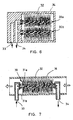
- a heat exchanger 30 as illustrated in Fig. 3 may also be mounted in a steam conduit, where steam will condense on the surface of the wires 32.
- Fig. 4 presents a cross-section of the heat exchanger 30 in Fig. 3. It can be seen from the figure that the heat transfer wires 32 mainly fill the duct 36 completely. The wires 32 are so thin that their air drag in the duct 36 is insignificant. Still, the total area of the wires 32 is so large that they produce efficient heat transfer.
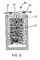
- Fig. 5 illustrates another way of using a heat exchanger 30.
- the heat exchanger 30 is placed e.g. in metal hydride powder 37.
- Heat transfer wires 32 and helical tubes 13 perform effectively also when heat is to be transferred into or from powder.
- Fig. 6 presents two heat exchangers 30a and 30b connected together so that the heat carrier liquid is supplied into both heat exchangers 30a and 30b via a common inlet channel 33.
- the heat exchangers 30a and 30b also have a common outlet channel 34.
- Fig. 7 presents a heat exchanger 30 placed in a duct 36 and comprising two separate tubes 31a and 31b twisted about each other.
- the adjacent ends of both helical tubes 31a and 31b at each end of the heat exchanger 30 are connected both to an inlet channel 33 and to an outlet channel 34.
- the heat carrier liquid flows in the same direction in both helical tubes 31a and 31b.
- the medium fed into the helical tube 31 may also be a vaporizable liquid, e.g. a vaporizable refrigerant in a cooling application.
- the duct 36 may also carry a steam flow, in which case the heat exchanger functions as a condenser as steam condenses on the wires 32.
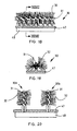
- Fig. 8 presents a diagrammatic cross-section of a heat exchanger unit 40 comprising seven heat exchangers 30 according to the invention mounted in a duct 36.
- the heat transfer wires 32 of each heat exchanger 30 partially intermesh with corresponding heat transfer wires 32 of adjacent heat exchangers 30.
- the duct 36 is so densely filled with heat transfer wires 32 that a good efficiency of the heat exchanger unit 40 is achieved.
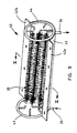
- Fig. 9 presents a heat exchanger unit 40 designed to be placed in a service door of a ventilation duct and comprising seven heat exchangers 30 grouped in the manner illustrated by Fig. 8. For the sake of clarity, Fig. 9 only shows some of the heat exchangers 30. For those heat exchangers that are not shown in Fig. 9, only the ends of the liquid supply pipes are depicted, to which the ends of the heat exchangers are connected.
- the heat exchanger unit 40 of Fig. 9 is provided with a support plate 41 of semicircular cross-section and flanges 42a and 42b comprised in it. Placed at each end of the heat exchanger unit 40 is a ring 43, 44. Ring 43 is an inlet ring supplying a heat transfer medium into all heat exchangers 30 in the heat exchanger unit 40. Correspondingly, ring 44 at the opposite end of the heat exchanger unit 40 is an outlet ring common to all the heat exchangers 30.
- the heat transfer medium is passed via the ring f to all the heat exchangers 30 in the heat exchanger unit 40.
- the following figures 11 and 12 show how the flanges 42a and 42b of the heat exchanger unit 40 can be fitted to corresponding flanges of a ventilation duct, with the support plate 41 forming part of the ventilation duct.
- Fig. 11 presents a ventilation duct 50 and a heat exchanger unit 40 designed to be fitted in it.
- the ventilation duct 50 is provided with a service door opening 51 located in its lower surface and having a size corresponding to the support plate 41.
- the heat exchanger unit 40 is mounted by placing its mounting flanges 42 against mounting flanges 52 provided at the edges of the service door opening 51.
- Fig. 12 presents the heat exchanger unit 40 installed in the service door opening of the ventilation duct 50.
- the heat exchangers 30 now fill the entire cross-sectional area of the ventilation duct 50.
- Fig. 12 shows in a diagrammatic form the topmost and bottommost heat exchangers in the duct 50 to visualize the placement of the heat exchangers in the ventilation duct 50.
- Fig. 13 presents an embodiment of the heat exchanger 30 in which the heat transfer wires 32 are squeezed between the spirals of a single helical tube 31.
- Fig. 14 presents a vaporizer 60 comprising a heat exchanger 30 placed in a chamber 61 and immersed in vaporizable liquid 62 in the chamber 61. Part of the heat transfer wires 32 of the heat exchanger 30 is inside the vaporizable liquid 62 and part of them is above the liquid surface, in the air space of the chamber 61.
- Fig. 15 presents a heat exchanger 30 comprising several elements 31 twisted about each other.
- the elements 31 may be rods, such as e.g. four rods, or two rods bent over against each other as shown in Fig. 16. In this case, heat transfer occurs by conduction via the rods 31.
- the elements 31 in Fig. 16 may also consist of tubes, as shown in the cross-sectional view in Fig. 17, in which case heat transfer occurs by the agency of a medium, such as a liquid, flowing through the tubes 31.
- Fig. 18 and 19 present a heat exchanger 30 designed for the cooling of electronic components.
- the core part 31 of the heat exchanger 30 and the cooling plate 47 attached to it can be mounted on top of a heat developing component 48, such as e.g. a microprocessor.
- Fig. 20 likewise presents an embodiment of the heat exchanger 30 in which the cooling plate 47 has been pressed e.g. onto an electronic component 48 to be cooled.
- the helical tubes 31 of the heat exchanger 30 are mounted in an upright position.
- Fig. 21 presents a cross-sectional view of an embodiment of the heat exchanger 30 consisting of a combination of nested heat exchangers. Placed inside the helical tubes 31a and 31b of the main heat exchanger 30 are corresponding heat exchangers 30a and 30b having core parts 31a and 31b of thin metal wire. Using such an arrangement, the internal heat transfer in the helical tubes 31a and 31b of the main heat exchanger 30 can be made more effective.
Landscapes
- Engineering & Computer Science (AREA)
- Physics & Mathematics (AREA)
- Thermal Sciences (AREA)
- Mechanical Engineering (AREA)
- General Engineering & Computer Science (AREA)
- Geometry (AREA)
- Heat-Exchange Devices With Radiators And Conduit Assemblies (AREA)
- Sealing Devices (AREA)
Applications Claiming Priority (2)
| Application Number | Priority Date | Filing Date | Title |
|---|---|---|---|
| FI20002454A FI20002454A7 (fi) | 2000-11-09 | 2000-11-09 | Lämmönsiirrin |
| FI20002454 | 2000-11-09 |
Publications (2)
| Publication Number | Publication Date |
|---|---|
| EP1205725A2 true EP1205725A2 (fr) | 2002-05-15 |
| EP1205725A3 EP1205725A3 (fr) | 2003-01-02 |
Family
ID=8559459
Family Applications (1)
| Application Number | Title | Priority Date | Filing Date |
|---|---|---|---|
| EP01660204A Withdrawn EP1205725A3 (fr) | 2000-11-09 | 2001-11-07 | Echangeur de chaleur |
Country Status (4)
| Country | Link |
|---|---|
| US (1) | US20020053422A1 (fr) |
| EP (1) | EP1205725A3 (fr) |
| CA (1) | CA2361207A1 (fr) |
| FI (1) | FI20002454A7 (fr) |
Cited By (1)
| Publication number | Priority date | Publication date | Assignee | Title |
|---|---|---|---|---|
| WO2004093496A1 (fr) * | 2003-04-02 | 2004-10-28 | Tutco, Inc. | Appareil chauffant avec resistance electrique a enroulement ouvert mettant en oeuvre des fils de resistance torsades et procedes de fabrication associes |
Families Citing this family (9)
| Publication number | Priority date | Publication date | Assignee | Title |
|---|---|---|---|---|
| US20100147486A1 (en) * | 2008-12-16 | 2010-06-17 | Jan Vetrovec | Thermal energy storage apparatus |
| IN2012DN00280A (fr) | 2009-07-10 | 2015-05-08 | Etalim Inc | |
| US9382874B2 (en) | 2010-11-18 | 2016-07-05 | Etalim Inc. | Thermal acoustic passage for a stirling cycle transducer apparatus |
| US10048019B2 (en) * | 2014-12-22 | 2018-08-14 | Hamilton Sundstrand Corporation | Pins for heat exchangers |
| US9988718B2 (en) | 2015-06-19 | 2018-06-05 | Rolls-Royce Corporation | Directed energy deposition with cooling mechanism |
| US10647060B2 (en) | 2016-11-23 | 2020-05-12 | Shapeways, Inc. | Techniques for manufacturing and cooling three-dimensional objects |
| US20180141285A1 (en) * | 2016-11-23 | 2018-05-24 | William Carter Davis | Techniques for manufacturing and cooling three-dimensional objects |
| US11071234B2 (en) * | 2018-10-30 | 2021-07-20 | Board Of Trastees Of The University Of Arkansas | Helical fin design by additive manufacturing of metal for enhanced heat sink for electronics cooling |
| US11187466B2 (en) * | 2019-07-26 | 2021-11-30 | Denso International America, Inc. | Heat exchanger and heat exchanging system |
Family Cites Families (4)
| Publication number | Priority date | Publication date | Assignee | Title |
|---|---|---|---|---|
| US3534814A (en) * | 1967-06-28 | 1970-10-20 | American Standard Inc | Heat exchanger construction |
| NZ243797A (en) * | 1991-07-31 | 1994-01-26 | Ronald Albert Pain | Opposed bayonet heat exchanger with spaced baffles: baffles formed by |
| DE19624937A1 (de) * | 1996-06-22 | 1998-01-02 | Dickgreber Johannes | Wärmetauscher |
| DE19701833A1 (de) * | 1997-01-21 | 1998-07-23 | Viessmann Werke Kg | Wärmetauscher |
-
2000
- 2000-11-09 FI FI20002454A patent/FI20002454A7/fi not_active Application Discontinuation
-
2001
- 2001-11-05 US US09/985,662 patent/US20020053422A1/en not_active Abandoned
- 2001-11-07 CA CA002361207A patent/CA2361207A1/fr not_active Abandoned
- 2001-11-07 EP EP01660204A patent/EP1205725A3/fr not_active Withdrawn
Cited By (2)
| Publication number | Priority date | Publication date | Assignee | Title |
|---|---|---|---|---|
| WO2004093496A1 (fr) * | 2003-04-02 | 2004-10-28 | Tutco, Inc. | Appareil chauffant avec resistance electrique a enroulement ouvert mettant en oeuvre des fils de resistance torsades et procedes de fabrication associes |
| CN100525546C (zh) * | 2003-04-02 | 2009-08-05 | 图特科有限公司 | 使用绞合电阻线的开放式线圈电气电阻加热器以及制造该加热器的方法 |
Also Published As
| Publication number | Publication date |
|---|---|
| CA2361207A1 (fr) | 2002-05-09 |
| US20020053422A1 (en) | 2002-05-09 |
| FI20002454L (fi) | 2002-05-10 |
| EP1205725A3 (fr) | 2003-01-02 |
| FI20002454A0 (fi) | 2000-11-09 |
| FI20002454A7 (fi) | 2002-05-10 |
Similar Documents
| Publication | Publication Date | Title |
|---|---|---|
| US6449979B1 (en) | Refrigerant evaporator with refrigerant distribution | |
| US6272881B1 (en) | Refrigerant evaporator and manufacturing method for the same | |
| EP2392886B1 (fr) | Tube de distributeur réfrigérant insensible à l'orientation | |
| TW552382B (en) | Evaporator, manufacturing method of the same, header for evaporator and refrigeration system | |
| JPH04132446U (ja) | 自動車のガソリン冷却装置 | |
| US2119761A (en) | Heat interchange device | |
| US20030178188A1 (en) | Micro-channel heat exchanger | |
| EP0751365A2 (fr) | Dispositif de transfert de chaleur avec une bande métallique pourvue d'orifices longitudinaux | |
| EP1205725A2 (fr) | Echangeur de chaleur | |
| US20050269069A1 (en) | Heat transfer apparatus with enhanced micro-channel heat transfer tubing | |
| US20150007780A1 (en) | Coil and serpentine bent fin tube condensing heat exchanger | |
| US20030196783A1 (en) | Refrigeration evaporator | |
| CN100447518C (zh) | 热交换器 | |
| US2792201A (en) | Heat exchanger | |
| CN109819635B (zh) | 散热装置 | |
| US7546867B2 (en) | Spirally wound, layered tube heat exchanger | |
| US8136578B2 (en) | Heat exchanger for EGR-gas | |
| CN108627035A (zh) | 换热组件和换热系统 | |
| JP4399925B2 (ja) | 犠牲腐食層の形成方法、熱交換器及び複式熱交換器 | |
| EP1475579A2 (fr) | Unité de condensation | |
| KR20100032388A (ko) | 가정용 냉장고들 및 냉동고들용 후벽 응축기 | |
| JPH0755380A (ja) | 熱交換器 | |
| US7913512B2 (en) | Air-heated heat exchanger | |
| JPH0653376A (ja) | 半導体素子冷却ユニット | |
| JP4224803B2 (ja) | 熱交換器 |
Legal Events
| Date | Code | Title | Description |
|---|---|---|---|
| PUAI | Public reference made under article 153(3) epc to a published international application that has entered the european phase |
Free format text: ORIGINAL CODE: 0009012 |
|
| AK | Designated contracting states |
Kind code of ref document: A2 Designated state(s): AT BE CH CY DE DK ES FI FR GB GR IE IT LI LU MC NL PT SE TR |
|
| AX | Request for extension of the european patent |
Free format text: AL;LT;LV;MK;RO;SI |
|
| PUAL | Search report despatched |
Free format text: ORIGINAL CODE: 0009013 |
|
| AK | Designated contracting states |
Kind code of ref document: A3 Designated state(s): AT BE CH CY DE DK ES FI FR GB GR IE IT LI LU MC NL PT SE TR |
|
| AX | Request for extension of the european patent |
Free format text: AL;LT;LV;MK;RO;SI |
|
| 17P | Request for examination filed |
Effective date: 20030702 |
|
| AKX | Designation fees paid |
Designated state(s): AT BE CH CY DE DK ES FI FR GB GR IE IT LI LU MC NL PT SE TR |
|
| 17Q | First examination report despatched |
Effective date: 20030905 |
|
| STAA | Information on the status of an ep patent application or granted ep patent |
Free format text: STATUS: THE APPLICATION IS DEEMED TO BE WITHDRAWN |
|
| 18D | Application deemed to be withdrawn |
Effective date: 20040116 |