EP1205764A2 - Verfahren, Gerät und System zur schnellen Erfassung von einem Spreizspektrumsignal - Google Patents
Verfahren, Gerät und System zur schnellen Erfassung von einem Spreizspektrumsignal Download PDFInfo
- Publication number
- EP1205764A2 EP1205764A2 EP01309427A EP01309427A EP1205764A2 EP 1205764 A2 EP1205764 A2 EP 1205764A2 EP 01309427 A EP01309427 A EP 01309427A EP 01309427 A EP01309427 A EP 01309427A EP 1205764 A2 EP1205764 A2 EP 1205764A2
- Authority
- EP
- European Patent Office
- Prior art keywords
- code
- frequency
- frequencies
- replica
- section
- Prior art date
- Legal status (The legal status is an assumption and is not a legal conclusion. Google has not performed a legal analysis and makes no representation as to the accuracy of the status listed.)
- Ceased
Links
Images


Classifications
-
- G—PHYSICS
- G01—MEASURING; TESTING
- G01S—RADIO DIRECTION-FINDING; RADIO NAVIGATION; DETERMINING DISTANCE OR VELOCITY BY USE OF RADIO WAVES; LOCATING OR PRESENCE-DETECTING BY USE OF THE REFLECTION OR RERADIATION OF RADIO WAVES; ANALOGOUS ARRANGEMENTS USING OTHER WAVES
- G01S19/00—Satellite radio beacon positioning systems; Determining position, velocity or attitude using signals transmitted by such systems
- G01S19/01—Satellite radio beacon positioning systems transmitting time-stamped messages, e.g. GPS [Global Positioning System], GLONASS [Global Orbiting Navigation Satellite System] or GALILEO
- G01S19/13—Receivers
- G01S19/24—Acquisition or tracking or demodulation of signals transmitted by the system
- G01S19/29—Acquisition or tracking or demodulation of signals transmitted by the system carrier including Doppler, related
Definitions
- This method relates, in general, to CDMA (Code Division Multiple Access) spread spectrum receivers, and more specifically, to fast acquisition GPS (Global Positioning System) receivers.
- CDMA Code Division Multiple Access
- GPS Global Positioning System
- Spread spectrum communication in its basic form is a method of taking a data signal that is used to modulate a sinusoidal carrier and then spreading its bandwidth to a much larger value, e.g. in a global positioning system (GPS) application by multiplying a single-frequency carrier by a high-rate binary (-1,1) pseudo-random noise (PRN) code sequence that is known to GPS users.
- the signal that is transmitted includes a data component, a PRN component, and a (sinusoidal) carrier component.
- a synchronized replica of the transmitted PRN code is required to de-spread the data sequence.
- Initial synchronization called acquisition
- fine synchronization which is called tracking.
- the present invention relates to acquisition of a spread spectrum signal. Acquisition is the process by which the replica PRN code is synchronized (to within a small timing offset) with the code conveyed by the received signal either for the first time or after losing a previously acquired signal, and also by which the carrier frequency of the received signal is determined.
- an acquisition system must accurately determine any frequency-shifting of the received signal from the transmitted frequency in order to accurately wipeoff (remove) the carrier signal.
- Frequency-shifting can be caused by relative motion of the transmitter and receiver (Doppler-shifting) as well as by clock inaccuracies (so that a transmitter and receiver sometimes do not agree on what is in fact the same frequency).
- the carrier frequency-shifting results in a modulation of a code component after carrier wipeoff in the receiver.
- the replica code sequence be not only time-aligned with the received code sequence, but also modulated to compensate for the frequency-shifting so as to fully eliminate the PRN sequence and leave behind only the data conveyed by the received signal.
- the acquisition process is therefore a two-dimensional search, a search both in code phase and in frequency.
- the search interval in the frequency domain can be as large as +/-6 kHz.
- the phase of the received code relative to the replica can be any possible value of code phase, due to uncertainties in position of the satellite and time of transmission of the received signal.
- a PRN code period is typically 1023 chips, the term chips being used to designate bits of code conveyed by the transmitted signal, as opposed to bits of data.
- the acquisition module of a receiver must search a 12 kHz-wide interval with 1023 ⁇ k s different code phases, where k s denotes the number of samples per chip.
- a GPS receiver designed for indoor operation must have an operating mode with equivalent noise bandwidth on the order of 10Hz in the acquisition stage. Even with an equivalent noise bandwidth as small as 10Hz though, for reliable tracking some post-detection filtering must still be performed as well as some further refining of the value determined for the carrier frequency in the acquisition stage.
- the granularity of 10Hz requires that the receiver search 1200 ⁇ k s ⁇ 1023 different code/frequency combinations and makes the sequential search so time-consuming as to be unrealistic, motivating the use of parallel and fast search methods.
- Some existing methods often intentionally modulate the signal being acquired, sequentially or in parallel, to advance the search in frequency.
- the present invention provides a method, a corresponding apparatus, and a corresponding system, for acquiring a received spread spectrum signal, the received signal having a carrier component at a carrier frequency, a code component having a code period, and a data component, the acquiring including matching the phase of a replica of the code component to the phase of the received code component and also determining a possible shift in the carrier frequency away from a nominal carrier frequency, the acquiring having an intrinsic bandwidth that is substantially the inverse of a predetermined fraction of a code period and also having a design bandwidth that is a fraction of the intrinsic bandwidth including possibly the entire intrinsic bandwidth, the method comprising the steps of: obtaining samples of the received signal spanning one code period after the received signal is demodulated at the nominal carrier frequency, the obtaining of the samples being performed at a sampling rate, the samples being distributed over a number of sections as a predetermined number of samples per section, the inverse of the product of the number of sections and the code period determining the intrinsic bandwidth; determining a first frequency from among an ordered set
- the correlations used in the acquisition process are continued over several code periods, the correlations over the several code periods being coherently combined (i.e. taking into account both the sign and the magnitude of each term being combined) using compensation factors based on different trial second frequencies.
- a system for acquiring a spread spectrum signal is not limited to acquiring a spread spectrum signal in any particular context, such as GPS, nor is it limited to acquiring a particular kind of spread spectrum signal.
- a system according to the present invention for acquiring a spread spectrum signal can be of use in any application in which a spread spectrum signal is to be acquired, as long as the spread spectrum signal includes a code component and a carrier component.
- x ( n ) s ( n ) + x noise ( n )
- the data bit duration is usually several code periods (usually 20 code periods in the case of a GPS signal).
- the effect of the data component of the received signal is to slowly modulate the received signal, and as long as correlations are performed over only a single code period or a relatively small number of code periods, the effect of the data modulation can be ignored.
- the common scaling factor Ae j ⁇ is also ignored since it does not affect the system design.
- the code phase is estimated based on calculating a correlation of the replica code with the incoming signal. The correlation is calculated using a sliding correlator, having taps with weights equal to the sample values of the replica, for successive positions of the received signal in the sliding correlator.
- An equivalent perspective is one in which the sliding correlator slides its replica over the received signal and computes a correlation for each successive position of the replica and so for different replica phases n mf measured with respect to the same arbitrary time or chip reference as the actual code phase n c , the quantity n mf being a cyclic variable with period equal to the number of samples of the replica.
- the correlation is a maximum (i.e. unity, if not degraded by a carrier frequency shift or modulation of the received signal by the data it conveys).
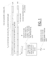
- Fig. 1 illustrates the notion of a sliding correlator computing a correlation c i ( n mf ) of a replica with a signal fragment with the same duration as the code period (the i th fragment counting from an arbitrary starting point) of the received signal, given by the argument i ⁇ N cp +n+n mf indicating that the correlation is over the i th set of N cp samples of the received signal (starting counting from an arbitrary time or sample reference), N cp being the number of samples acquired during one code period.
- the code component is usually a pseudo random number (PRN) code. Due to special properties of such codes, the correlator output is significantly smaller when the replica is not aligned with the received code, and the correlator output is maximal at the position at which the replica phase coincides with that of the code component of the received signal.
- PRN pseudo random number
- one code period for replica length is used, and samples of the received signal sequentially shift into a block of shift registers having a combined length N cp (spanning one code period). Each further received sample shifts the already received samples one position forward in the block of shift registers, and the portion of the received signal so obtained, having length N cp , is correlated with the replica.
- the correlation is the summation of the element-wise multiplication of the replica and the portion of the received signal in the shift register block, as indicated by equation (1A) for a correlation over a single code period, or equation (1B) for a correlation over a number K cp of code periods.
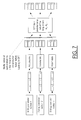
- Fig. 2 illustrates performing a correlation over several code periods, what might be called a super correlation, according to equation (1B).
- Any frequency shift in the received signal should be compensated for prior to calculating the correlation between the received signal and the replica because a frequency shift modulates the received signal via the sinusoid exp ⁇ jw ( n - n c + n mf ) ⁇ (see equation (1B)), disturbing the correlation.
- the frequency shift, if any, is not known a priori; thus, a two-dimensional search must be performed in acquiring the received signal, a search for both the code phase and any frequency shift.
- the received signal should be demodulated using a compensating factor of exp(- jw andn ), where n is an index corresponding to the different samples of the received signal (and so corresponds indirectly to a series of instants of time).
- the compensating factor of exp(- jw andn ) the correlation of equation (1B) becomes,
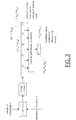
- Fig. 3 illustrates calculating the correlation between the code component of the received signal and a replica according to equation (2).
- Such a sliding correlator has an intrinsic bandwidth that is the inverse of the code period (1kHz in case of a GPS signal). Not all of the intrinsic bandwidth must be used, however, and in the present invention, the amount of the intrinsic bandwidth that is used is chosen to give a balance between bandwidth (used), aliasing, and frequency resolution. (In case of using a multi-section sliding correlator, as discussed below, the intrinsic bandwidth of the sliding correlator is the number of sections multiplied by the intrinsic bandwidth for a single-section sliding correlator.)
- a frequency shift compensation can be performed before computing the correlation in coarse steps of up to approximately 1kHz for a GPS signal, followed by a fine frequency shift compensation in fine steps of less than 1kHz (or whatever coarse step is used) on the output of the correlation.
- the choice of a particular coarse frequency step, a design choice is limited to values less than the intrinsic bandwidth of the sliding correlator, which is in turn dictated by the code period.
- the value chosen for the coarse frequency step is here called the design bandwidth.
- the K cp N cp samples of the received signal over which a correlation is to be performed are multiplied (mixed) by a coarse compensation sinusoid exp(- jw c n ), with the index n indicating the current incoming signal sample.
- the one-code-period-long correlation is performed in a correlator (inner summation).
- the one-code-period-long correlation results are combined a number of times equal to the number of fine frequency shifts w f (outer summation). This is performed for each code phase n mf .
- Equation (3) an approximation of equation (2), is valid only for frequency shifts within a coarse frequency step of the (trial) coarse frequency being used in the correlation.
- correlations are also computed in a way similar to what is indicated by equation (3), but in the present invention, the correlations are computed over sections of a code period using a multi-section correlator (one section for each fraction of the code period), not an entire code period, as in equation (3).
- the (full) correlations over an entire code period are combined into a single, super correlation over several code periods, and in the present invention, as discussed below in connection with Fig. 5, several section correlations are combined again into a super correlation, the super correlation then again amounting to a correlation over several code periods.
- one correlation calculation for each possible code phase n mf is used to check for different fine frequency shifts in a 1kHz range about a trial coarse frequency shift. More specifically, for one fine frequency one needs several sequential outputs of the correlator corresponding to the same phase. With a sliding correlator type implementation, the sequential outputs for the given phase are one code period apart.
- the index k cp references those sequential outputs; it specifies a particular correlator output value, for a particular code phase, and several such output values are needed to perform the correlation computations for a fine frequency, the outputs being combined using a compensation factor that depends on the fine frequency. In other words, perform the following steps:
- Equation (3) has two drawbacks.
- the searching for the fine frequency shift is usually done using calculations at the different possible fine frequency shifts performed in parallel, while the coarse frequency compensation is performed on the input to the correlation calculation.
- the present invention acquisition parameterized for balancing aliasing cancellation, resolution, and bandwidth
- the correlation process can be split into several section correlations, each performed using only a fraction of the K cp N cp samples of the received signal, or in other words the samples in a section of the received signal.
- Each such section correlation can then be implemented using a section of a multi-section sliding correlator.
- An acquisition system using such a multi-section sliding correlator analyzes the alignment of the replica code with the code component of the received signal by correlating the sections of the replica with the sections of the received signal saved at the current stage (corresponding to the position of the received signal) in the shift register block of the multi-section sliding correlator.
- the (full) correlation, for each fine frequency, of the replica with the one-code-period-long portion of the received signal is obtained by combining properly the section correlations for each fine frequency.
- K cp N se section outputs are available for each value of n mf .
- the process therefore uses K cp N cp samples, providing outputs at K cp N cp different stages (positions of the received signal).
- the section outputs for a given n mf are accumulated (stored) one by one until all such K cp are stored. They are then multiplied by a compensation factor, corresponding to a particular fine frequency and section number, and added to produce a unique output for that fine frequency and corresponding to the given n mf .
- an accumulating variable instead of accumulating the section outputs for each n mf performing the correlation calculation after all necessary section outputs are stored to obtain the correlation for a particular fine frequency and code phase n mf , an accumulating variable, initialized to zero, is used and each section output is multiplied by the compensation factor for the particular fine frequency being tried and added the accumulating variable as soon as the section output becomes available.
- the section correlations from the different sections of the sliding correlator are combined using particular coefficients (compensation factors).
- compensation factors coefficients that are aligned. Then component-wise multiplication of the replica with the code component of the received signal wipes off the code component, and what is left in the received signal is modulation by the data being conveyed by the received signal and sinusoidal modulation due to any frequency shift.
- N c is the number of such noncoherent additions
- N cp N ss N se
- K cp K cp successive full correlations are combined to yield a super correlation
- n n ss + n se N ss + k cp N ss N se is a dummy index ranging over all such N samples (and so corresponding to different instants of time, since each sample arrives at a different instant of time).
- equation (3a) computes first a section correlation for each section, via the innermost summation working in combination with the middle summation, but in the process accumulates the section correlations into a correlation for a single code period.
- the outermost summation, the summation over the number of code periods (i.e. over k cp ) and the middle summation (over n se ) in combination compute the correlation over K cp code periods, i.e. a super correlation.
- Equation (3a) shows only what is here called coherent combining of terms of a (compensated) correlation, i.e. each term in a summation over a set of terms is accumulated taking into account both its magnitude and its sign.
- the method of the present invention also comprehends using a non-coherent combining of terms, i.e. reckoning a summation of only the magnitudes of terms in a set of terms, or, in other words, reckoning a summation of terms by taking the magnitude of each term to be summed and accumulating the magnitude in the summation without regard for the sign of the term.
- the invention comprehends forming a non-coherent combining of several different (full) correlations c ( n mf , k cp , w c ) (correlations over a single code period) for each replica code phase and for each fine frequency compensation factor, i.e. forming the non-coherent super correlation,
- the invention also comprehends performing a non-coherent combining of either two or more super correlations so as to form the quantity (what might be called a grand correlation of type 1), or performing a non-coherent combining of two or more non-coherent super correlations so as to form the quantity (what might be called a grand correlation of type 2),
- the present invention differs from the prior art in that it uses an N se -section correlator to provide N se correlations each over a different 1/ N th / se of a code period. These section correlations are then combined to form a (full, one-code-period-long) correlation, and then, as in the prior art, the correlations are accumulated over several full code periods to provide a super correlation. (As explained below, however, the present invention also provides for a balancing of various competing features of an acquisition system, namely aliasing cancellation, frequency resolution and bandwidth.)
- the correlation (a section correlation) performed by each section of the correlator adds the pure sinusoidal modulations (neglecting the data modulation) according to, where
- the multi-section sliding correlator acts like a lowpass filter when the replica and code component of the received signal are aligned; the low frequency sinusoids pass through the correlator, while high frequency sinusoids are suppressed.
- a frequency interval extending to ⁇ 500Hz about any given coarse frequency is the search area for a fine frequency shift in this case, and fine frequency shifts of up to 500Hz from a given coarse frequency are compensated for after the correlation operation, not before.
- Compensating for the fine frequency shift after the correlation operation is important if the output of the correlator is processed in parallel and for many frequencies in the 1kHz interval about a coarse frequency since only one correlator processing stage is needed and the fine frequency compensation after the correlator is performed at a significantly slower rate, thus requiring less computational load.
- a balancing of aliasing cancellation, frequency resolution and design bandwidth is performed using a multi-section sliding correlator.
- the intrinsic bandwidth is the inverse of 1/ N th / se of a code period, i.e. the inverse of the interval spanned by a section of the correlator.
- An increase in N se increases the intrinsic bandwidth of the sliding correlator, as indicated by F ss ( w ).
- N se sections of the correlator In general, with N se sections of the correlator, one can choose to increase the design bandwidth N se times (compared to the design bandwidth for a single-section correlator), but there is a tradeoff. Increasing the number N se of sections allows increasing the design bandwidth, but also increases the complexity of the acquisition. Since any implementation of an acquisition system according to equation (5) will necessarily have finite resources (memory and computing index), the resources available for parallel processing in performing the fine frequency compensation and the required resolution of the acquisition dictate the design bandwidth and thus the number N se of sections for the correlator.
- Fig. 5 illustrates an acquisition process according to equation (7), and so the acquisition process of Fig. 4 modified to provide aliasing cancellation by using a multi-section sliding correlator and performing corresponding section correlations which are then combined (using a fine frequency shift compensation factor) to yield a (full) correlation (for one code period), a correlation which may be combined with correlations for other code periods to yield a super correlation.
- the duration of a data bit is 20 msec in a typical GPS signal, which is why the accumulation of correlation results should never be performed for more than 20 code periods, preferably from 10 to 16 code periods.
- the above computation can be performed using a discrete Fourier transform (DFT).
- DFT discrete Fourier transform
- Equation (9) can be rewritten to make explicit the DFT.
- equation (9) becomes, where The single sum of equation (9') makes explicit that the correlation is a DFT of the quantity .
- the frequency span for the case when a DFT is used is maximum, i.e. fine frequencies are in the range of N se kHz (meaning ⁇ N se /2 kHz about any given coarse frequency shift), the maximum possible bandwidth.
- the design bandwidth is equal to the intrinsic bandwidth when a DFT is used, at least when a DFT is used without any special arrangements.
- the resolution is 1/ K cp kHz.
- two of the three parameters B , f res , and N f are chosen independently to strike a desired balance between the contradictory requirements of aliasing cancellation (the more sections the better), design bandwidth (the smaller the design bandwidth, the better the aliasing cancellation), and frequency resolution or, correspondingly, parallelism (the greater the number of fine frequencies the greater the parallelism).
- the design bandwidth B is thus divided among N f subbands, i.e. among the N f fine frequencies spanning the interval between any two adjacent coarse frequencies.
- a DFT to perform the correlation does not allow controlling the design bandwidth (unless special techniques are used to allow controlling the design bandwidth).
- a grid can be used to adjust the design bandwidth B when the correlation is performed using direct computation of the correlation according to equation (7) or other techniques for the fast computation of the correlation according to equation (7).
- the system is completely defined so as to achieve any desired trade-off between aliasing cancellation, bandwidth increase and frequency resolution.
- Fig. 6 shows an implementation of the present invention in which section correlations are accumulated over several code periods, then used to compute the correlator outputs compensated based on various fine frequencies.
- the implementation of Fig. 6 can be based on the DFT technique, as indicated in Fig. 7, which shows an implementation in which the entire intrinsic bandwidth is used as the design bandwidth, although, as mentioned above, it is possible to use DFT to perform the correlations and adjust the design bandwidth to be less than the entire intrinsic bandwidth.
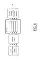
- Fig. 8 illustrates an architecture for use in accumulating the section correlation results, an architecture providing memory resources that are allocated differently depending on the tradeoff desired between bandwidth, resolution, and aliasing cancellation.
- the memory size is the code period multiplied by the number of correlator sections and also by the number of code periods. Thus, memory could be allocated either to the number of code periods (better frequency resolution) or to the number of sections (greater separation of coarse frequencies).
- a trading off between resolution and design bandwidth is done first by using appropriate fine frequency compensating factors exp ⁇ - jw f N ss ( n se + k cp N se ) ⁇ .
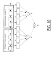
- correlations for variable section lengths can be made using a tree of adders (as indicated in Fig. 10 below), i.e. correlations can be made using one or another number of sections all of the same length, but a length chosen to give the desired tradeoff between bandwidth and resolution.
- the desired tradeoff is achieved by choosing how many fine frequencies to use and by choosing how many sections of a sliding correlator to implement.
- Fig. 9 illustrates another implementation, one in which the effect of any frequency shift is compensated for in each section correlation, and the section correlations are then combined, for each fine frequency, to yield a (full) correlation, which are then (optionally) accumulated over several periods to yield a super correlation. No accumulation of section correlations is performed in such an implementation.
- Fig. 10 illustrates one possible way of implementing the section correlations performed by either above implementation as a block of shift registers and adders.
- the section correlation results can then be combined to form section correlations of different lengths and even a (full) correlation output, i.e. a correlation over one entire code period, when needed.
Landscapes
- Engineering & Computer Science (AREA)
- Radar, Positioning & Navigation (AREA)
- Remote Sensing (AREA)
- Computer Networks & Wireless Communication (AREA)
- Physics & Mathematics (AREA)
- General Physics & Mathematics (AREA)
- Position Fixing By Use Of Radio Waves (AREA)
Applications Claiming Priority (2)
| Application Number | Priority Date | Filing Date | Title |
|---|---|---|---|
| US708966 | 2000-11-08 | ||
| US09/708,966 US6735243B1 (en) | 2000-11-08 | 2000-11-08 | Method, apparatus and system for fast acquisition of a spread spectrum signal |
Publications (2)
| Publication Number | Publication Date |
|---|---|
| EP1205764A2 true EP1205764A2 (de) | 2002-05-15 |
| EP1205764A3 EP1205764A3 (de) | 2004-08-18 |
Family
ID=24847922
Family Applications (1)
| Application Number | Title | Priority Date | Filing Date |
|---|---|---|---|
| EP01309427A Ceased EP1205764A3 (de) | 2000-11-08 | 2001-11-07 | Verfahren, Gerät und System zur schnellen Erfassung von einem Spreizspektrumsignal |
Country Status (2)
| Country | Link |
|---|---|
| US (1) | US6735243B1 (de) |
| EP (1) | EP1205764A3 (de) |
Cited By (2)
| Publication number | Priority date | Publication date | Assignee | Title |
|---|---|---|---|---|
| WO2005003807A1 (en) * | 2003-07-03 | 2005-01-13 | Nemerix Sa | Gps receiver with fast acquisition time |
| US7551132B2 (en) | 2004-07-02 | 2009-06-23 | Nemerix Sa | GPS receiver with fast acquisition time |
Families Citing this family (18)
| Publication number | Priority date | Publication date | Assignee | Title |
|---|---|---|---|---|
| US6990140B2 (en) | 2001-05-17 | 2006-01-24 | Trimble Navigation Limited | Signal receiver using coherent integration in interleaved time periods for signal acquisition at low signal strength |
| US7164736B2 (en) * | 2001-06-22 | 2007-01-16 | Sirf Technology, Inc. | Synthesizing coherent correlation sums at one or multiple carrier frequencies using correlation sums calculated at a course set of frequencies |
| US7027534B2 (en) * | 2001-06-22 | 2006-04-11 | Sirf Technology, Inc. | Extracting fine-tuned estimates from correlation functions evaluated at a limited number of values |
| US6898234B1 (en) * | 2001-06-27 | 2005-05-24 | Trimble Navigation Limited | Signal receiver for integrating and combining integrations in alternating time segments for signal acquisition at low signal strength |
| US7499428B2 (en) * | 2002-11-07 | 2009-03-03 | Qualcomm, Incorporated | Method, apparatus, and system for receiving data on a first frequency band and observing a second frequency band |
| US20050050130A1 (en) * | 2003-09-02 | 2005-03-03 | Dabak Anand G. | Ranging in multi-band OFDM communications systems |
| US7702002B2 (en) * | 2004-01-28 | 2010-04-20 | Qualcomm Incorporated | Rapid acquisition methods and apparatus for GPS signals |
| US7548199B2 (en) | 2004-09-20 | 2009-06-16 | The United States Of America As Represented By The Administrator Of The National Aeronautics And Space Administration | Radiation-hardened fast acquisition/weak signal tracking system and method |
| KR101097853B1 (ko) * | 2005-11-30 | 2011-12-23 | 삼성전자주식회사 | 시변 위상에 적응적으로 동작하는 상관방법 및 그 상관기 |
| US8391339B2 (en) * | 2006-07-05 | 2013-03-05 | CSR Technology Holdings Inc. | Correlator sum method for spread spectrum signal receivers |
| US8396097B1 (en) * | 2007-06-25 | 2013-03-12 | L-3 Communications Corp | IIR sliding window integrator and search engine delay component for reducing the preamble size of a discovery burst |
| US7940834B2 (en) * | 2008-05-15 | 2011-05-10 | Trimble Navigation Limited | Signal receiver using data bit search in alternating time segments |
| US8212720B2 (en) * | 2008-09-24 | 2012-07-03 | Texas Instruments Incorporated | Detecting lack of movement to aid GNSS receivers |
| ES2622283T3 (es) | 2010-11-02 | 2017-07-06 | Qualcomm Incorporated | Transmisión de retroalimentación de solicitud de repetición automática híbrida en un sistema de comunicación de múltiples portadoras de componentes usando recursos de solicitud de planificación |
| US8717922B2 (en) * | 2011-01-28 | 2014-05-06 | Nec Laboratories America, Inc. | Multitaper spectrum sensing systems and methods |
| FR2971653B1 (fr) * | 2011-02-11 | 2013-03-22 | Sagem Defense Securite | Procede d'acquisition avec multi-correlation frequentielle amelioree |
| US11630217B2 (en) * | 2019-05-21 | 2023-04-18 | Deere & Company | Methods and devices for global navigation satellite system (GNSS) signal acquisition |
| CN115685271B (zh) * | 2022-12-29 | 2023-03-17 | 中国人民解放军国防科技大学 | 一种大多普勒下时分导航信号的两级快速信号捕获方法 |
Family Cites Families (9)
| Publication number | Priority date | Publication date | Assignee | Title |
|---|---|---|---|---|
| US5579338A (en) * | 1992-06-29 | 1996-11-26 | Mitsubishi Denki Kabushiki Kaisha | Spread spectrum receiver using partial correlations |
| US5402347A (en) * | 1993-07-22 | 1995-03-28 | Trimble Navigation Limited | Satellite search methods for improving time to first fix in a GPS receiver |
| US6151353A (en) * | 1996-07-12 | 2000-11-21 | General Electric Company | Pre-acquisition frequency offset removal in a GPS receiver |
| JP3376224B2 (ja) * | 1996-10-23 | 2003-02-10 | 株式会社エヌ・ティ・ティ・ドコモ | Ds−cdma基地局間非同期セルラ方式における初期同期方法および受信機 |
| GB9724048D0 (en) | 1997-11-14 | 1998-01-14 | Univ Edinburgh | Communications terminal and operating method |
| US6363049B1 (en) * | 1998-03-25 | 2002-03-26 | Sony Corporation | Adaptive acquisition system for CDMA and spread spectrum systems compensating for frequency offset and noise |
| EP0975100A1 (de) * | 1998-07-23 | 2000-01-26 | Siemens Aktiengesellschaft | Verfahren und Empfänger für Wiedergewinnung von Daten in einen Funksignal |
| US6137433A (en) * | 1999-03-18 | 2000-10-24 | The United States Of America As Represented By The Secretary Of Commerce | Scatterometer with adaptable spatial resolution |
| JP3322240B2 (ja) * | 1999-05-10 | 2002-09-09 | 日本電気株式会社 | Cdma受信機 |
-
2000
- 2000-11-08 US US09/708,966 patent/US6735243B1/en not_active Expired - Lifetime
-
2001
- 2001-11-07 EP EP01309427A patent/EP1205764A3/de not_active Ceased
Cited By (3)
| Publication number | Priority date | Publication date | Assignee | Title |
|---|---|---|---|---|
| WO2005003807A1 (en) * | 2003-07-03 | 2005-01-13 | Nemerix Sa | Gps receiver with fast acquisition time |
| EP2290832A3 (de) * | 2003-07-03 | 2011-03-23 | Qualcomm Incorporated | GPS empfänger mit kurzer Akquisitionszeit |
| US7551132B2 (en) | 2004-07-02 | 2009-06-23 | Nemerix Sa | GPS receiver with fast acquisition time |
Also Published As
| Publication number | Publication date |
|---|---|
| EP1205764A3 (de) | 2004-08-18 |
| US6735243B1 (en) | 2004-05-11 |
Similar Documents
| Publication | Publication Date | Title |
|---|---|---|
| US6735243B1 (en) | Method, apparatus and system for fast acquisition of a spread spectrum signal | |
| US7224721B2 (en) | System for direct acquisition of received signals | |
| JP5059268B2 (ja) | スペクトル拡散受信機用信号捕捉システム | |
| US7876811B2 (en) | Method and apparatus for detecting spreading-code synchronization for spectrum spreading signals | |
| EP1071966B1 (de) | Angepasster Filter | |
| US7042930B2 (en) | Spread spectrum bit boundary correlation search acquisition system | |
| US9223028B2 (en) | System and method for fast code phase and carrier frequency acquisition in GPS receiver | |
| US20040196894A1 (en) | Determining the correlation between received samples and available replica samples | |
| US20050254560A1 (en) | Apparatus and method for acquiring spread-spectrum signals | |
| KR20030060975A (ko) | 정합 필터로 gps 신호를 프로세싱하는 방법 및 장치 | |
| JP3906913B2 (ja) | スペクトラム拡散信号復調方法および装置 | |
| US20040141574A1 (en) | Determination of the code phase between a code modulated signal and a replica code sequence | |
| US7277476B2 (en) | Determining the correlation between received samples and available replica samples | |
| Sagiraju et al. | Block correlator for tracking GPS/GNSS Signals | |
| US7286594B2 (en) | Determination of the correlation phase between a signal and a replica sequence | |
| JP2004510136A (ja) | 時間シフトされた信号発生方法 | |
| KR20020050242A (ko) | 스프레드 스펙트럼 수신기용 신호 어퀴지션 시스템 | |
| HK1035932B (en) | Fast acquisition, high sensitivity gps receiver | |
| AU8756098A (en) | Fast acquisition, high sensitivity gps receiver | |
| HK1129143A (en) | A method and system related to implementing information of satellite signal received from several kinds of satellite system |
Legal Events
| Date | Code | Title | Description |
|---|---|---|---|
| PUAI | Public reference made under article 153(3) epc to a published international application that has entered the european phase |
Free format text: ORIGINAL CODE: 0009012 |
|
| AK | Designated contracting states |
Kind code of ref document: A2 Designated state(s): AT BE CH CY DE DK ES FI FR GB GR IE IT LI LU MC NL PT SE TR |
|
| AX | Request for extension of the european patent |
Free format text: AL;LT;LV;MK;RO;SI |
|
| PUAL | Search report despatched |
Free format text: ORIGINAL CODE: 0009013 |
|
| AK | Designated contracting states |
Kind code of ref document: A3 Designated state(s): AT BE CH CY DE DK ES FI FR GB GR IE IT LI LU MC NL PT SE TR |
|
| AX | Request for extension of the european patent |
Extension state: AL LT LV MK RO SI |
|
| 17P | Request for examination filed |
Effective date: 20050216 |
|
| AKX | Designation fees paid |
Designated state(s): AT BE CH CY DE DK ES FI FR GB GR IE IT LI LU MC NL PT SE TR |
|
| 17Q | First examination report despatched |
Effective date: 20050415 |
|
| STAA | Information on the status of an ep patent application or granted ep patent |
Free format text: STATUS: THE APPLICATION HAS BEEN REFUSED |
|
| 18R | Application refused |
Effective date: 20111024 |