EP1205775A1 - Polariseur - Google Patents
Polariseur Download PDFInfo
- Publication number
- EP1205775A1 EP1205775A1 EP01126604A EP01126604A EP1205775A1 EP 1205775 A1 EP1205775 A1 EP 1205775A1 EP 01126604 A EP01126604 A EP 01126604A EP 01126604 A EP01126604 A EP 01126604A EP 1205775 A1 EP1205775 A1 EP 1205775A1
- Authority
- EP
- European Patent Office
- Prior art keywords
- retardation
- polarizing element
- film
- light
- transparent protective
- Prior art date
- Legal status (The legal status is an assumption and is not a legal conclusion. Google has not performed a legal analysis and makes no representation as to the accuracy of the status listed.)
- Granted
Links
- 230000001681 protective effect Effects 0.000 claims abstract description 48
- 238000010521 absorption reaction Methods 0.000 claims abstract description 30
- 229920002451 polyvinyl alcohol Polymers 0.000 claims description 9
- 239000004372 Polyvinyl alcohol Substances 0.000 claims description 8
- ZCYVEMRRCGMTRW-UHFFFAOYSA-N 7553-56-2 Chemical compound [I] ZCYVEMRRCGMTRW-UHFFFAOYSA-N 0.000 claims description 2
- 229910052740 iodine Inorganic materials 0.000 claims description 2
- 239000011630 iodine Substances 0.000 claims description 2
- 150000001875 compounds Chemical class 0.000 claims 1
- 239000010410 layer Substances 0.000 description 32
- 230000000052 comparative effect Effects 0.000 description 30
- 230000008859 change Effects 0.000 description 26
- 230000003287 optical effect Effects 0.000 description 14
- 229920000642 polymer Polymers 0.000 description 13
- 238000002834 transmittance Methods 0.000 description 12
- 230000005540 biological transmission Effects 0.000 description 11
- 230000000694 effects Effects 0.000 description 11
- 239000010419 fine particle Substances 0.000 description 9
- 239000004973 liquid crystal related substance Substances 0.000 description 9
- 239000006185 dispersion Substances 0.000 description 8
- 238000000034 method Methods 0.000 description 8
- 230000009466 transformation Effects 0.000 description 8
- 239000000853 adhesive Substances 0.000 description 7
- 230000001747 exhibiting effect Effects 0.000 description 7
- 229920002284 Cellulose triacetate Polymers 0.000 description 5
- 229920006257 Heat-shrinkable film Polymers 0.000 description 5
- NNLVGZFZQQXQNW-ADJNRHBOSA-N [(2r,3r,4s,5r,6s)-4,5-diacetyloxy-3-[(2s,3r,4s,5r,6r)-3,4,5-triacetyloxy-6-(acetyloxymethyl)oxan-2-yl]oxy-6-[(2r,3r,4s,5r,6s)-4,5,6-triacetyloxy-2-(acetyloxymethyl)oxan-3-yl]oxyoxan-2-yl]methyl acetate Chemical compound O([C@@H]1O[C@@H]([C@H]([C@H](OC(C)=O)[C@H]1OC(C)=O)O[C@H]1[C@@H]([C@@H](OC(C)=O)[C@H](OC(C)=O)[C@@H](COC(C)=O)O1)OC(C)=O)COC(=O)C)[C@@H]1[C@@H](COC(C)=O)O[C@@H](OC(C)=O)[C@H](OC(C)=O)[C@H]1OC(C)=O NNLVGZFZQQXQNW-ADJNRHBOSA-N 0.000 description 5
- 238000004040 coloring Methods 0.000 description 5
- 230000008569 process Effects 0.000 description 5
- 239000011241 protective layer Substances 0.000 description 5
- KQOMUSLQKQAVTD-UHFFFAOYSA-N sodium 4-hydroxy-3-[(4-nitrophenyl)diazenyl]naphthalene-1,5-disulfonic acid Chemical compound C1=CC2=C(C=C(C(=C2C(=C1)S(=O)(=O)O)O)N=NC3=CC=C(C=C3)[N+](=O)[O-])S(=O)(=O)O.[Na+] KQOMUSLQKQAVTD-UHFFFAOYSA-N 0.000 description 5
- 238000006073 displacement reaction Methods 0.000 description 4
- 230000010287 polarization Effects 0.000 description 4
- 239000012790 adhesive layer Substances 0.000 description 3
- 239000003795 chemical substances by application Substances 0.000 description 3
- 239000000470 constituent Substances 0.000 description 3
- 239000000975 dye Substances 0.000 description 3
- 238000010438 heat treatment Methods 0.000 description 3
- 238000005259 measurement Methods 0.000 description 3
- 230000007935 neutral effect Effects 0.000 description 3
- 229920006254 polymer film Polymers 0.000 description 3
- -1 polypropylene Polymers 0.000 description 3
- 239000011347 resin Substances 0.000 description 3
- 229920005989 resin Polymers 0.000 description 3
- VYPSYNLAJGMNEJ-UHFFFAOYSA-N Silicium dioxide Chemical compound O=[Si]=O VYPSYNLAJGMNEJ-UHFFFAOYSA-N 0.000 description 2
- PPBRXRYQALVLMV-UHFFFAOYSA-N Styrene Chemical compound C=CC1=CC=CC=C1 PPBRXRYQALVLMV-UHFFFAOYSA-N 0.000 description 2
- GWEVSGVZZGPLCZ-UHFFFAOYSA-N Titan oxide Chemical compound O=[Ti]=O GWEVSGVZZGPLCZ-UHFFFAOYSA-N 0.000 description 2
- MCMNRKCIXSYSNV-UHFFFAOYSA-N Zirconium dioxide Chemical compound O=[Zr]=O MCMNRKCIXSYSNV-UHFFFAOYSA-N 0.000 description 2
- NIXOWILDQLNWCW-UHFFFAOYSA-N acrylic acid group Chemical group C(C=C)(=O)O NIXOWILDQLNWCW-UHFFFAOYSA-N 0.000 description 2
- 239000007864 aqueous solution Substances 0.000 description 2
- 239000011247 coating layer Substances 0.000 description 2
- 238000001035 drying Methods 0.000 description 2
- 239000011521 glass Substances 0.000 description 2
- 230000006872 improvement Effects 0.000 description 2
- 238000003475 lamination Methods 0.000 description 2
- 230000007774 longterm Effects 0.000 description 2
- 229920000058 polyacrylate Polymers 0.000 description 2
- 229920000515 polycarbonate Polymers 0.000 description 2
- 239000004417 polycarbonate Substances 0.000 description 2
- 229920000728 polyester Polymers 0.000 description 2
- 229920002635 polyurethane Polymers 0.000 description 2
- 239000004814 polyurethane Substances 0.000 description 2
- 230000009467 reduction Effects 0.000 description 2
- YCKRFDGAMUMZLT-UHFFFAOYSA-N Fluorine atom Chemical compound [F] YCKRFDGAMUMZLT-UHFFFAOYSA-N 0.000 description 1
- 239000004721 Polyphenylene oxide Substances 0.000 description 1
- 239000004743 Polypropylene Substances 0.000 description 1
- DPOPAJRDYZGTIR-UHFFFAOYSA-N Tetrazine Chemical compound C1=CN=NN=N1 DPOPAJRDYZGTIR-UHFFFAOYSA-N 0.000 description 1
- PNEYBMLMFCGWSK-UHFFFAOYSA-N aluminium oxide Inorganic materials [O-2].[O-2].[O-2].[Al+3].[Al+3] PNEYBMLMFCGWSK-UHFFFAOYSA-N 0.000 description 1
- 239000001000 anthraquinone dye Substances 0.000 description 1
- 229910000410 antimony oxide Inorganic materials 0.000 description 1
- 239000000987 azo dye Substances 0.000 description 1
- 230000015572 biosynthetic process Effects 0.000 description 1
- KGBXLFKZBHKPEV-UHFFFAOYSA-N boric acid Chemical compound OB(O)O KGBXLFKZBHKPEV-UHFFFAOYSA-N 0.000 description 1
- 239000004327 boric acid Substances 0.000 description 1
- CXKCTMHTOKXKQT-UHFFFAOYSA-N cadmium oxide Inorganic materials [Cd]=O CXKCTMHTOKXKQT-UHFFFAOYSA-N 0.000 description 1
- CFEAAQFZALKQPA-UHFFFAOYSA-N cadmium(2+);oxygen(2-) Chemical compound [O-2].[Cd+2] CFEAAQFZALKQPA-UHFFFAOYSA-N 0.000 description 1
- BRPQOXSCLDDYGP-UHFFFAOYSA-N calcium oxide Chemical compound [O-2].[Ca+2] BRPQOXSCLDDYGP-UHFFFAOYSA-N 0.000 description 1
- ODINCKMPIJJUCX-UHFFFAOYSA-N calcium oxide Inorganic materials [Ca]=O ODINCKMPIJJUCX-UHFFFAOYSA-N 0.000 description 1
- 239000000292 calcium oxide Substances 0.000 description 1
- 229920002678 cellulose Polymers 0.000 description 1
- 239000001913 cellulose Substances 0.000 description 1
- 238000010276 construction Methods 0.000 description 1
- 229920006037 cross link polymer Polymers 0.000 description 1
- 230000007423 decrease Effects 0.000 description 1
- 230000006866 deterioration Effects 0.000 description 1
- 238000009792 diffusion process Methods 0.000 description 1
- 239000000428 dust Substances 0.000 description 1
- 230000005684 electric field Effects 0.000 description 1
- 238000004049 embossing Methods 0.000 description 1
- 238000005530 etching Methods 0.000 description 1
- 238000011156 evaluation Methods 0.000 description 1
- 229910052731 fluorine Inorganic materials 0.000 description 1
- 239000011737 fluorine Substances 0.000 description 1
- 229910003437 indium oxide Inorganic materials 0.000 description 1
- PJXISJQVUVHSOJ-UHFFFAOYSA-N indium(iii) oxide Chemical compound [O-2].[O-2].[O-2].[In+3].[In+3] PJXISJQVUVHSOJ-UHFFFAOYSA-N 0.000 description 1
- 229940077844 iodine / potassium iodide Drugs 0.000 description 1
- 238000010030 laminating Methods 0.000 description 1
- 239000002346 layers by function Substances 0.000 description 1
- 239000000203 mixture Substances 0.000 description 1
- JFNLZVQOOSMTJK-KNVOCYPGSA-N norbornene Chemical compound C1[C@@H]2CC[C@H]1C=C2 JFNLZVQOOSMTJK-KNVOCYPGSA-N 0.000 description 1
- VTRUBDSFZJNXHI-UHFFFAOYSA-N oxoantimony Chemical compound [Sb]=O VTRUBDSFZJNXHI-UHFFFAOYSA-N 0.000 description 1
- 239000002245 particle Substances 0.000 description 1
- 230000035515 penetration Effects 0.000 description 1
- 229920003207 poly(ethylene-2,6-naphthalate) Polymers 0.000 description 1
- 229920003229 poly(methyl methacrylate) Polymers 0.000 description 1
- 229920002492 poly(sulfone) Polymers 0.000 description 1
- 229920000570 polyether Polymers 0.000 description 1
- 239000011112 polyethylene naphthalate Substances 0.000 description 1
- 229920000139 polyethylene terephthalate Polymers 0.000 description 1
- 239000005020 polyethylene terephthalate Substances 0.000 description 1
- 239000004926 polymethyl methacrylate Substances 0.000 description 1
- 229920000098 polyolefin Polymers 0.000 description 1
- 229920001155 polypropylene Polymers 0.000 description 1
- 230000002633 protecting effect Effects 0.000 description 1
- 230000002787 reinforcement Effects 0.000 description 1
- 238000007788 roughening Methods 0.000 description 1
- 238000005488 sandblasting Methods 0.000 description 1
- 239000000377 silicon dioxide Substances 0.000 description 1
- 229920005573 silicon-containing polymer Polymers 0.000 description 1
- 238000001179 sorption measurement Methods 0.000 description 1
- 230000003595 spectral effect Effects 0.000 description 1
- 229920003051 synthetic elastomer Polymers 0.000 description 1
- 239000005061 synthetic rubber Substances 0.000 description 1
- XOLBLPGZBRYERU-UHFFFAOYSA-N tin dioxide Chemical compound O=[Sn]=O XOLBLPGZBRYERU-UHFFFAOYSA-N 0.000 description 1
- 229910001887 tin oxide Inorganic materials 0.000 description 1
- XLYOFNOQVPJJNP-UHFFFAOYSA-N water Substances O XLYOFNOQVPJJNP-UHFFFAOYSA-N 0.000 description 1
Images


Classifications
-
- G—PHYSICS
- G02—OPTICS
- G02B—OPTICAL ELEMENTS, SYSTEMS OR APPARATUS
- G02B5/00—Optical elements other than lenses
- G02B5/30—Polarising elements
-
- G—PHYSICS
- G02—OPTICS
- G02F—OPTICAL DEVICES OR ARRANGEMENTS FOR THE CONTROL OF LIGHT BY MODIFICATION OF THE OPTICAL PROPERTIES OF THE MEDIA OF THE ELEMENTS INVOLVED THEREIN; NON-LINEAR OPTICS; FREQUENCY-CHANGING OF LIGHT; OPTICAL LOGIC ELEMENTS; OPTICAL ANALOGUE/DIGITAL CONVERTERS
- G02F1/00—Devices or arrangements for the control of the intensity, colour, phase, polarisation or direction of light arriving from an independent light source, e.g. switching, gating or modulating; Non-linear optics
- G02F1/01—Devices or arrangements for the control of the intensity, colour, phase, polarisation or direction of light arriving from an independent light source, e.g. switching, gating or modulating; Non-linear optics for the control of the intensity, phase, polarisation or colour
- G02F1/13—Devices or arrangements for the control of the intensity, colour, phase, polarisation or direction of light arriving from an independent light source, e.g. switching, gating or modulating; Non-linear optics for the control of the intensity, phase, polarisation or colour based on liquid crystals, e.g. single liquid crystal display cells
- G02F1/133—Constructional arrangements; Operation of liquid crystal cells; Circuit arrangements
- G02F1/1333—Constructional arrangements; Manufacturing methods
- G02F1/1335—Structural association of cells with optical devices, e.g. polarisers or reflectors
- G02F1/133528—Polarisers
-
- G—PHYSICS
- G02—OPTICS
- G02B—OPTICAL ELEMENTS, SYSTEMS OR APPARATUS
- G02B5/00—Optical elements other than lenses
- G02B5/30—Polarising elements
- G02B5/3083—Birefringent or phase retarding elements
-
- G—PHYSICS
- G02—OPTICS
- G02F—OPTICAL DEVICES OR ARRANGEMENTS FOR THE CONTROL OF LIGHT BY MODIFICATION OF THE OPTICAL PROPERTIES OF THE MEDIA OF THE ELEMENTS INVOLVED THEREIN; NON-LINEAR OPTICS; FREQUENCY-CHANGING OF LIGHT; OPTICAL LOGIC ELEMENTS; OPTICAL ANALOGUE/DIGITAL CONVERTERS
- G02F1/00—Devices or arrangements for the control of the intensity, colour, phase, polarisation or direction of light arriving from an independent light source, e.g. switching, gating or modulating; Non-linear optics
- G02F1/01—Devices or arrangements for the control of the intensity, colour, phase, polarisation or direction of light arriving from an independent light source, e.g. switching, gating or modulating; Non-linear optics for the control of the intensity, phase, polarisation or colour
- G02F1/13—Devices or arrangements for the control of the intensity, colour, phase, polarisation or direction of light arriving from an independent light source, e.g. switching, gating or modulating; Non-linear optics for the control of the intensity, phase, polarisation or colour based on liquid crystals, e.g. single liquid crystal display cells
- G02F1/133—Constructional arrangements; Operation of liquid crystal cells; Circuit arrangements
- G02F1/1333—Constructional arrangements; Manufacturing methods
- G02F1/1335—Structural association of cells with optical devices, e.g. polarisers or reflectors
- G02F1/13363—Birefringent elements, e.g. for optical compensation
- G02F1/133634—Birefringent elements, e.g. for optical compensation the refractive index Nz perpendicular to the element surface being different from in-plane refractive indices Nx and Ny, e.g. biaxial or with normal optical axis
Definitions
- the present invention relates to a polarizer by which light leakage based on changes of polarizing element axes caused by a change of a viewing angle between polarizing elements disposed in the form of crossed-Nicol can be prevented in a wide range of the visible light to thereby achieve liquid-crystal display of a wide viewing angle, or the like.
- the background-art polarizer was provided to compensate for the displacement in absorption axis or the like between polarizing elements due to the change of the viewing angle as follows.
- a transparent protective film to be bonded to one or each of opposite surfaces of a polarizing element for improving durability against penetration of moisture or the like a film exhibiting retardation characteristic of about a half wavelength with respect to visible light was used instead of an isotropic transparent protective film constituted by a triacetylcellulose (TAC) film or the like exhibiting little birefringence which had been generated otherwise.
- TAC triacetylcellulose
- wavelength dispersion which is a phenomenon that the retardation varies in accordance with the wavelength
- the function of the retardation film as a half-wave plate works only for light with a specific wavelength.
- the retardation film cannot function as a half-wave plate accurately, so that the light with the other wavelengths is inferior in the characteristic of linear polarization.
- a coloring problem when the characteristic of the retardation film is optimized to compensate for light with a wavelength near to 550 nm exhibiting a maximum value in luminous efficiency, light with the other wavelengths is colored in blue because the condition for the light is displaced from the aforementioned optimizing condition.
- the coloring problem reveals itself as a problem in deterioration of neutral characteristic of display.
- An object of the present invention is to develop a polarizer in which light leakage hardly occurs while coloring owing to wavelength dispersion hardly occurs to thereby achieve excellent neutral characteristic even in the case where polarizing elements disposed in the form of crossed-Nicol are obliquely viewed at an azimuth displaced from the optical axis thereof.
- a polarizer which exhibits a compensating function for canceling the change of an optical axis such as an absorption axis of a polarizing element by changing an optical axis such as a slow axis of each of retardation films constituting a transparent protective film in accordance with the change of a viewing angle so that both light leakage and wavelength dispersion of retardation can be suppressed not only at an azimuth parallel with the optical axis of polarizing elements disposed in the form of crossed-Nicol but also at an azimuth displaced from the optical axis to thereby achieve excellent neutral characteristic (colorlessness) and make linear polarization characteristic difficult to change.
- the use of the polarizer permits the formation of a liquid-crystal display device, or the like, excellent in display quality such as high contrast ratio at a wide viewing angle.
- the polarizer is excellent in reduction of thickness and weight because the two layers of retardation films serve as a transparent protective film.
- the polarizing element it is possible to use a suitable one capable of transmitting linearly polarized light when natural light is made incident on the polarizing element, without any particular limitation.
- the preferred polarizing element is a polarizing element by which transmitted light excellent in the degree of polarization can be obtained with good light transmittance.
- an absorption-dichromatic polarizing element which transmits linearly polarized light while absorbing the other light when natural light is made incident on the polarizing element.
- the absorption-dichromatic polarizing element is preferably made of a polarizing film.
- the absorption-dichromatic polarizing element may be constituted by an oriented layer obtained by applying a liquid-crystal dichromatic dye.
- the absorption-dichromatic polarizing element made of a polarizing film it is also possible to use any suitable one. From the point of view of obtaining linearly polarized light in a wide wave range of the visible light, or the like, it is possible to use a polyvinyl alcohol film made of a polymer such as polyvinyl alcohol or partially formalized polyvinyl alcohol, the film being oriented and aligned after impregnated with iodine or/and a dichromatic dye such as an azo dye, an anthraquinone dye, a tetrazine dye, or the like, by a suitable system such as an adsorption system. Especially, a uniaxially oriented film is preferably used.
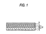
- the transparent protective films 2 and 3 are bonded/laminated onto one or both of opposite surfaces of the polarizing element 1.
- at least the transparent protective film 2, which is disposed on one of the opposite surfaces of the polarizing element 1 is made of two layers of retardation films 21 and 22 constituted by a combination of a retardation film with Nz of from 0.65 to 0.85 and a retardation film with Nz of from 0.15 to 0.35, each of the retardation films exhibiting an in-plane retardation of from 190 to 320 nm with respect to light having a wavelength of 550 nm.
- Nz (nx - nz)/(nx - ny) on the condition of nx > ny when nx and ny are in-plane refractive indices of each retardation film, and nz is a refractive index in a direction of the thickness of each retardation film.
- the two layers of retardation films are bonded/laminated to/on each other so that the slow axis of each of the retardation films is parallel with the absorption axis of the polarizing element.
- the parallel relationship between the slow axis and the absorption axis does not mean a perfect parallel state in terms of accuracy in working or the like.
- the slow axis of each of the retardation films and the absorption axis of the polarizing element are based on the viewing angle from the front (azimuth angle: 0).
- the sequence of laminating the retardation films with different Nz can be selected at option.
- the retardation film 22 with Nz of from 0.15 to 0.35 is bonded/laminated onto the polarizing element 1 through the retardation film 21 with Nz of from 0.65 to 0.85.
- This sequence of arrangement is preferred from the point of view of the compensating effect.
- each of the retardation films can be obtained as a birefringent film constituted by a polymer film oriented by a suitable system such as a uniaxial orientation system, a biaxial orientation system, or the like.
- a retardation film excellent in light transmittance and little in alignment unevenness and retardation unevenness is used preferably.
- a retardation film exhibiting the aforementioned characteristics of retardation and Nz can be formed by a suitable method such as a method in which a heat-shrinkable film is bonded to a polymer film and oriented under the function of shrinking force of the heat-shrinkable film by heating to thereby control the refractive index in the direction of the thickness, a method in which a polymer film is obtained while controlling alignment by applying an electric field in the direction of the thickness and then the film is oriented, or the like.
- the retardation and Nz can be changed by changing the kind of polymer or the orientation condition of the film to be processed, the kind of the heat-shrinkable film, the applied voltage, and so on.
- Nz is set to be not larger than 0 or not smaller than 1.
- the polymer forming the retardation film it is possible to use a suitable one without any particular limitation. Especially, a polymer excellent in transparency is preferred. From the point of view of suppressing the change of the retardation caused by the generation of stress, a polymer with a small photoelastic coefficient is preferred.
- the preferred polymer include: polycarbonate; polyallylate; polysulfone; polyolefin such as polypropylene; polyester such as polyethylene terephthalate or polyethylene naphthalate; vinyl alcohol polymer; norbornene polymer; acrylic polymer; styrene polymer; cellulose polymer; mixture polymer of two kinds or three or more kinds of the aforementioned polymers; and so on.
- the bonding/lamination of the polarizing element onto the transparent protective film or onto the retardation film as one of constituent members of the transparent protective film is provided for the purposes of: improving the protecting effect; preventing the optical axis from being displaced; preventing foreign matter such as dust or the like from entering the polarizing element; and so on.
- the bonding/lamination can be performed by a suitable system such as a bonding system using a transparent adhesive layer or the like.
- the adhesive agent used in the system is not particularly limited.
- an adhesive agent not requiring any high-temperature process at the time of curing/drying is preferred and an adhesive agent not requiring any long-term curing process or any long- term drying time is preferred.
- a polyvinyl alcohol adhesive agent or a tackiness agent can be used preferably.
- the adhesive layer for bonding the retardation film and the polarizing element to each other is not shown in Fig. 1.
- the tackiness agent it is possible to use one that is formed from a suitable polymer such as acrylic polymer, silicone polymer, polyester, polyurethane, polyether, synthetic rubber, or the like. Especially, an acrylic tackiness agent is preferred from the point of view of optical transparency, tackiness, weather resistance, and so on.
- the adhesive layer 4, especially the tacky layer may be provided on one or each of opposite surfaces of the polarizer for the purpose of bonding the polarizer onto a subject to be bonded such as a liquid-crystal cell or the like, as occasion demands.
- a separator or the like may be temporarily attached to the tacky layer until the surface of the tacky layer is exposed to the outside and put into practical use.
- such transparent protective films provided for suitable purposes such as improvement in reinforcement, heat resistance, humidity resistance, or the like, may be disposed on opposite surfaces of the polarizing element 1 as occasion demands.
- one of the transparent protective films may be formed, in accordance with the background art, as a coating layer of a suitable resin such as TAC or a layer of a laminate of resin films when the transparent protective film is not made of the aforementioned retardation film.
- the transparent protective layer provided in the aforementioned case preferably, has a retardation as small as possible in order to maintain the above-mentioned compensating effect. If there is some retardation, it is preferable that Nz is 0 or 1 or near 0 or 1.
- the transparent protective layer with Nz of 0 or near 0 is preferably provided so that a fast axis of the layer is parallel with the absorption axis of the polarizing element.
- the transparent protective layer with Nz of 1 or near 1 is preferably provided so that the slow axis of the layer is parallel with the absorption axis of the polarizing element.
- FIGs. 2A to 2C are schematic views each using a Poincare sphere for showing a state of displacement of the axis of the polarizer owing to the change of the viewing angle.
- Fig. 2A shows the polarizer according to the present invention.
- Figs. 2B and 2C show the background-art polarizers, respectively. That is, Fig. 2B shows the polarizer according to Unexamined Japanese Patent Publication No. Hei.
- a transparent protective film exhibiting birefringence with a retardation of from 190 to 320 nm and with Nz of from 0.1 to 0.9 is disposed so that the slow axis of the transparent protective film is parallel with the absorption axis of a polarizing element.
- Fig. 2C shows the polarizer in which a film having an in-plane retardation not larger than about 30 nm and having Nz in a range of from 1 to 30 is used as the transparent protective film.
- the radius expresses a viewing angle.
- the thick line shows a state in which the apparent angle of the optical axis changes in accordance with the change of the viewing angle viewed from the direction of zero degree on the condition that the absorption axis A of the polarizing element is arranged at 45 degrees.
- the change of the optical axis is larger than the real change for explanation's sake .
- Figs . 2A to 2C show the absorption axis A of the polarizing element and the slow axis S of each retardation film (transparent protective film), the relationship between the transmission axis of the polarizing element and the fast axis of the retardation film also changes in the same manner as in Figs.
- the absorption axis A of the polarizing element changes to become gradually parallel with the viewing angle in accordance with the change of the viewing angle. That is, the angle of the absorption axis A in each of Figs. 2A to 2C changes largely from its original angle.
- the transmission axis T (broken line) parallel with the absorption axis A in the case where another polarizing element is disposed on the retardation film side of the polarizer in the form of crossed-Nicol, changes in a direction reverse to the absorption axis A in accordance with the change of the viewing angle, and the displacement in angle between the transmission axis T and the absorption axis A increases gradually.
- the cases in Figs. 2A and 2C show the same changes as described above.
- the angle of the slow axis S3 of the transparent protective film can be regarded as zero degree because the slow axis S3 is generated always approximately horizontally with respect to the viewing angle in accordance with the change of the viewing angle. Moreover, the retardation gradually increases in accordance with the change of the viewing angle.
- the maximum value of the retardation is about 40 nm
- light ⁇ transmitted through the polarizing element is subjected to rotational transformation with the slow axis S3 as its center on the Poincare sphere.
- the magnitude of the function varies in accordance with the wavelength of the light, so that the rotational speed of the light increases as the wavelength of the light decreases (wavelength dispersion).
- the light ⁇ broadens from ⁇ blue to ⁇ red as shown in Fig. 2C.
- the transmittance of the light transmitted through the polarizing element of the transmission axis T is also influenced by the retardation caused by the transparent protective film so that the transmittance of the light increases (light leakage).
- the angle hardly changes when Nz of the slow axis S2 of the transparent protective film takes a value which is in a range of from 0.1 to 0.9 and which is in the vicinity of 0.5 (0.5 in Fig. 2B).
- the axial change of the slow axis S2 due to the viewing angle hardly occurs.
- the influence of the retardation does not appear because the optical axis of the transparent protective film coincides with that of the polarizing element in the frontal direction, but the influence of the retardation appears when the optical axis of the transparent protective film and the optical axis of the polarizing element are displaced from each other.
- the in-plane retardation is equal to about a half wavelength of visible light.
- light ⁇ transmitted through the polarizing element is subjected to rotational transformation by ⁇ with the slow axis S2 as its center on the Poincare sphere, so that the light ⁇ is transformed into a position substantially symmetrical with the absorption axis A about the slow axis S2.
- the light ⁇ approximately becomes the linearly polarized light at an angle near the angle changed in accordance with the change of the transmission axis T of the polarizing element disposed in the form of crossed-Nicol, so that the light ⁇ is compensated for to maintain the relation of crossed-Nicol.
- the light leakage is reduced remarkably.
- the retardation is displaced from a half wavelength, so that the angle of the rotational transformation formed thus cannot be exactly ⁇ but to be larger or smaller than ⁇ .
- the resulting light is displaced from the angle changed in accordance with the change of the transmission axis T of the polarizing element disposed in the form of crossed-Nicol, or the elliptically polarized light.
- the light is transmitted through the polarizing element of the transmission axis T, so that light leakage in blue or red occurs as shown in Fig 2C to thereby result in increase in the perpendicularly crossing transmittance or to thereby cause coloring.
- the slow axis S21 of the retardation film 21 as one of constituent members of the transparent protective film 2 in the polarizer according to the present invention changes by an angle in the vicinity of a half of the difference between its original angle and the changed angle of the absorption axis A because Nz of the retardation film is in a range of from 0.65 to 0.85 (0.75 in Fig. 2A).
- Nz of the retardation film is in a range of from 0.65 to 0.85 (0.75 in Fig. 2A).
- the change of the axis owing to the viewing angle always becomes about 1/2 as large as the change of the absorption axis A.
- the influence of the retardation appears along with the axial displacement between the retardation film 21 and the polarizing element in the same manner as in Fig.
- the slow axis S22 of the retardation film 22 is displaced to an axis symmetrical with the changed slow axis S21.
- the slow axis S22 of the retardation film 22 having Nz to be 0.25 is changed symmetrically with the change of the slow axis S21 of the retardation film 21 having Nz to be 0.75, so that the slow axis S22 is changed, relative to the absorption axis A, to be 1/2 as large as the change in angle of the transmission axis T of the polarizing element disposed in the form of crossed-Nicol.
- the light ⁇ blue to ⁇ red subjected to rotational transformation in the retardation film 21 is further subjected to rotational transformation by ⁇ with the slow axis S22 as its center on the Poincare sphere.
- the light broadens from ⁇ blue to ⁇ red because of wavelength dispersion.
- the change in this case has a function for canceling the previous change.
- the light is compensated for so as to converge at an angle sustantially equal to the transmission axis T of the polarizing element disposed in the form of crossed-Nicol regardless of the wavelength as shown in Fig. 2A.
- the relation of cross-Nicol can be maintained with respect to the substantially whole range of wavelength. For example, even in the case where the central wavelength is 550 nm, light leakage in blue or red is prevented so that coloring of the transmitted light is prevented.
- the polarizer according to the present invention can be used preferably for the suitable purpose in accordance with the background art, for example, for the purpose of forming a liquid-crystal display device or the like.
- suitable functional layers such as a protective layer for various kinds of purposes, an anti-reflection layer or/and an anti-glare layer for the purpose of preventing surface reflection or the like, a light-diffusing layer, and so on, may be provided on one or both of opposite surfaces of the polarizer.
- the anti-reflection layer can be formed suitably as a light-coherent film such as a fluorine polymer coat layer, a multilayer metal-deposited film, or the like.
- the anti-glare layer can be also formed by a suitable system in which, for example, a resin coating layer containing fine particles is applied or a fine roughness structure is provided on a surface by a suitable system such as embossing, sandblasting, etching, or the like, to thereby diffuse surface-reflected light.
- a suitable system such as embossing, sandblasting, etching, or the like, to thereby diffuse surface-reflected light.
- the light-diffusing layer can be also formed in the same manner as the anti-glare layer.
- examples of the fine particles may include inorganic fine particles and organic fine particles with an average particle size of from 0.5 to 20 ⁇ m.
- the inorganic fine particles are made of silica, calcium oxide, alumina, titania, zirconia, tin oxide, indium oxide, cadmium oxide, antimony oxide, etc. and may be electrically conductive.
- the organic fine particles are made of suitably crosslinked or non-crosslinked polymers such as polymethyl methacrylate and polyurethane. One member or a combination of two or more members suitably selected from the inorganic fine particles and the organic fine particles maybe used as the fine particles.
- the anti-glare layer or the light-diffusing layer may be formed to be integrated with the transparent protective film by diffusion, surface-roughening, or the like, of the transparent protective film.
- the liquid-crystal display device can be formed by use of the polarizer according to the present invention instead of the background-art polarizer and by disposing the polarizer on one or each of opposite sides of the liquid-crystal cell.
- the transparent protective film constituted by two layers of retardation films is disposed so as to be located between the polarizing element and the liquid-crystal cell.
- the location of the transparent protective film is not limited thereto.
- a polyvinyl alcohol film was immersed in hot water so as to be swollen. Then, the film was dyed in an aqueous solution of iodine/potassium iodide and uniaxially oriented in an aqueous solution of boric acid to thereby obtain a polarizing element. Simplex transmittance, parallel transmittance and cross transmittance of the polarizing element were measured by a spectrophotometer. As a result, the transmittance was 43.5 % and the degree of polarization was 99.9 %.
- Heat-shrinkable films were bonded to opposite surfaces of a polycarbonate (PC) film through tacky layers respectively.
- the resulting film was uniaxially oriented under heating to thereby obtain a retardation film A with an in-plane retardation of 268 nm and Nz of 0.74 with respect to light with a wavelength of 550 nm (this rule will apply hereunder).
- a retardation film B with an in-plane retardation of 260 nm and Nz of 0.26 was obtained.
- a TAC film was bonded to one surface of the polarizing element obtained in Reference Example through a polyvinyl alcohol adhesive agent to thereby form a transparent protective layer.
- a transparent protective film which was constituted by the retardation film A bonded onto the other surface of the polarizing element through a polyvinyl alcohol adhesive agent, and the retardation film B superposedly bonded onto the retardation film A through an acrylic tacky layer was formed.
- a polarizer constituted by the polarizing element and the transparent protective film was obtained.
- the orientation axis in each of the retardation films served as the slow axis, so that bonding was performed so that the slow axis was parallel with the absorption axis of the polarizing element.
- a polarizer was obtained in the same manner as in Example 1 except that a retardation film A with an in-plane retardation of 265 nm and Nz of 0.82 and a retardation film B with an in-plane retardation of 260 nm and Nz of 0.21 were obtained and used in Example 2.
- a polarizer was obtained in the same manner as in Example 1 except that a retardation film A with an in-plane retardation of 259 nm and Nz of 0.67 and a retardation film B with an in-plane retardation of 262 nm and Nz of 0.32 were obtained and used in Example 3.
- a polarizer was obtained in the same manner as in Example 1 except that the transparent protective film constituted by the retardation films A and B was replaced by a transparent protective film constituted by a TAC film with an in-plane retardation of 6 nm and Nz of 8.
- a polarizer was obtained in the same manner as in Example 1 except that the retardation filmAwas replaced by a retardation film with an in-plane retardation of 265 nm and Nz of 1.01.
- the retardation film was uniaxially oriented under heating without any heat-shrinkable film bonded thereto.
- a polarizer was obtained in the same manner as in Example 1 except that a retardation film A with an in-plane retardation of 630 nm and Nz of 0.91 and a retardation film B with an in-plane retardation of 515 nm and Nz of 0.67 were obtained and used in Comparative Example 3.
- a polarizer was obtained in the same manner as in Example 1 except that a retardation film A with an in-plane retardation of 263 nm and Nz of 0.41 and a retardation film B with an in-plane retardation of 255 nm and Nz of 0.17 were obtained and used in Comparative Example 4.
- a polarizer was obtained in the same manner as in Example 1 except that a retardation film A with an in-plane retardation of 274 nm and Nz of 0.94 and a retardation film B with an in-plane retardation of 277 nm and Nz of 0.92 were obtained and used in Comparative Example 5.
- a polarizer was obtained in the same manner as in Example 1 except that the transparent protective film constituted by the retardation films A and B was replaced by a transparent protective film constituted by a retardation film with an in-plane retardation of 260 nm and Nz of 0.75.
- the retardation film was obtained in the same manner as in Example 1.
- the spectroscopic intensity in the polarizer obtained in each of Examples 1 to 3 and Comparative Examples 1 to 6 was measured by an apparatus shown in Fig. 3. That is, parallel rays were generated by a combination of a light source K, a pinhole P and lenses R. The parallel rays were made incident onto a sample S constituted by the polarizer obtained in each of Examples 1 to 3 and Comparative Examples 1 to 6. Light transmitted through the sample S passed through a spectroscope B and was received by a detector D, so that the spectroscopic intensity of the light was measured.
- the sample S is obtained by bonding a transparent protective film side (constituted by retardation films, a retardation film, or the like) of the polarizer onto a surface of a glass plate through a tacky layer so as to make the absorption axis of the polarizer be inclined to the side at an angle of 45 degrees, and by bonding another polarizing element onto the other surface of the glass plate through another tacky layer in the form of crossed-Nicol.
- a transparent protective film side constituted by retardation films, a retardation film, or the like
- the sample S was mounted onto a rotary stage capable of rotating by ⁇ around a rotation axis ⁇ perpendicular to the parallel rays so that the transparent protective film (constituted by the retardation film(s)) of the sample S was disposed on the light source side so as to be perpendicular to the light rays and so that the absorption axis of the polarizing element was formed 45 degrees with respect to the rotation axis ⁇ .
- Transmittance was calculated from the ratio of the spectroscopic intensity measured as described above to reference spectroscopic intensity.
- L, a and b were calculated from the transmittance value on the basis of three stimulus values, so that the color difference ⁇ E0 from a black point was obtained.
- spectral transmittance was measured in the same manner as described above on the condition that the sample S was rotated by 75 degrees around the rotation axis ⁇ . Hence, the color difference ⁇ E75 from a black point was obtained. At the same time, the color difference ⁇ E75-0 was calculated from the color coordinates at the respective rotational angles of 0 degree and 75 degrees on the basis of results of the aforementioned measurement.
- the reference spectroscopic intensity was based on the spectroscopic intensity of the apparatus in the condition that the sample S was removed from the apparatus shown in Fig. 3.
- Comparative Example 4 the compensating effect was smaller and the light leakage was larger in comparison with that in each of Examples 1 to 3.
- Comparative Example 5 light leakage was generated to have the same level as that in Comparative Example 1 and the improving effect was not found. Accordingly, it is apparent that the combination of Nz according to the present invention is essential to appearance of the required compensating effect.
- Comparative Example 6 the color difference ⁇ E75 was smaller than that in Comparative Example 1 but the values of a and b were large so that transmitted light was discolored in violet even in eye observation. This means that optimal compensation was not made for the blue or red region. It was confirmed that the color difference ⁇ E gradually increased and discoloring (light leakage) gradually increased even in eye observation as the rotational angle increased within a range between 0 degree and 75 degrees.
Landscapes
- Physics & Mathematics (AREA)
- Nonlinear Science (AREA)
- General Physics & Mathematics (AREA)
- Optics & Photonics (AREA)
- Mathematical Physics (AREA)
- Chemical & Material Sciences (AREA)
- Crystallography & Structural Chemistry (AREA)
- Polarising Elements (AREA)
- Liquid Crystal (AREA)
Applications Claiming Priority (2)
| Application Number | Priority Date | Filing Date | Title |
|---|---|---|---|
| JP2000340416A JP2002148433A (ja) | 2000-11-08 | 2000-11-08 | 偏光板 |
| JP2000340416 | 2000-11-08 |
Publications (2)
| Publication Number | Publication Date |
|---|---|
| EP1205775A1 true EP1205775A1 (fr) | 2002-05-15 |
| EP1205775B1 EP1205775B1 (fr) | 2004-10-20 |
Family
ID=18815335
Family Applications (1)
| Application Number | Title | Priority Date | Filing Date |
|---|---|---|---|
| EP01126604A Expired - Lifetime EP1205775B1 (fr) | 2000-11-08 | 2001-11-07 | Polariseur |
Country Status (5)
| Country | Link |
|---|---|
| US (1) | US6961180B2 (fr) |
| EP (1) | EP1205775B1 (fr) |
| JP (1) | JP2002148433A (fr) |
| KR (1) | KR100779307B1 (fr) |
| TW (1) | TWI224686B (fr) |
Cited By (1)
| Publication number | Priority date | Publication date | Assignee | Title |
|---|---|---|---|---|
| CN115826299A (zh) * | 2021-08-31 | 2023-03-21 | 夏普显示科技株式会社 | 光学元件和具备光学元件的液晶显示装置 |
Families Citing this family (14)
| Publication number | Priority date | Publication date | Assignee | Title |
|---|---|---|---|---|
| ATE513236T1 (de) * | 2002-03-25 | 2011-07-15 | Zeon Corp | Optischer film und prozess zu seiner herstellung |
| KR100925330B1 (ko) * | 2002-11-26 | 2009-11-04 | 엘지디스플레이 주식회사 | 액정표시장치 편광판 제조방법 |
| JP4882376B2 (ja) | 2003-11-21 | 2012-02-22 | 日本ゼオン株式会社 | 液晶表示装置 |
| US7667793B2 (en) | 2003-11-21 | 2010-02-23 | Zeon Corporation | Liquid crystal display device |
| JP3841306B2 (ja) * | 2004-08-05 | 2006-11-01 | 日東電工株式会社 | 位相差フィルムの製造方法 |
| JP2006091836A (ja) * | 2004-08-26 | 2006-04-06 | Nitto Denko Corp | 位相差フィルムおよびその製造方法、ならびに、該位相差フィルムを用いた光学フィルム、液晶パネルおよび液晶表示装置 |
| JP2006071705A (ja) * | 2004-08-31 | 2006-03-16 | Konica Minolta Opto Inc | 偏光板及び液晶表示装置 |
| US7821598B2 (en) * | 2006-12-21 | 2010-10-26 | Nitto Denko Corporation | Method of manufacturing polarizer, polarizer, polarizing plate, and image display |
| JP4878306B2 (ja) * | 2007-02-09 | 2012-02-15 | 株式会社 日立ディスプレイズ | 液晶表示装置 |
| TWI637197B (zh) * | 2013-08-09 | 2018-10-01 | 住友化學股份有限公司 | Optical film |
| KR101691691B1 (ko) * | 2013-12-30 | 2016-12-30 | 제일모직주식회사 | 편광자, 이의 제조방법, 이를 포함하는 편광판 및 이를 포함하는 광학표시장치 |
| JP6797537B2 (ja) * | 2016-03-11 | 2020-12-09 | 日東電工株式会社 | 光学補償層付偏光板およびそれを用いた有機elパネル |
| JP7334047B2 (ja) * | 2019-03-13 | 2023-08-28 | 日東電工株式会社 | 画像表示装置および該画像表示装置に用いられる円偏光板 |
| KR102859724B1 (ko) * | 2020-03-18 | 2025-09-15 | 삼성디스플레이 주식회사 | 표시 장치 |
Citations (4)
| Publication number | Priority date | Publication date | Assignee | Title |
|---|---|---|---|---|
| US2441049A (en) * | 1944-09-29 | 1948-05-04 | Polaroid Corp | Composite achromatic wave plates comprising superimposed sheets of differently birefringent, molecularly oriented, transparent, solid, organic plastic material |
| EP0350075A2 (fr) * | 1988-07-08 | 1990-01-10 | Kabushiki Kaisha Toshiba | Dispositif d'affichage à cristal liquide |
| US5227903A (en) * | 1991-09-20 | 1993-07-13 | Casio Computer Co., Ltd. | Liquid crystal display device with at least one biaxial retardation film having nx >nz >ny |
| US5594568A (en) * | 1993-12-15 | 1997-01-14 | Ois Optical Imaging Systems, Inc. | LCD with a pair of retardation films on one side of normally white liquid crystal layer |
Family Cites Families (4)
| Publication number | Priority date | Publication date | Assignee | Title |
|---|---|---|---|---|
| JPH0223304A (ja) | 1988-07-12 | 1990-01-25 | Toray Ind Inc | 可視偏光フイルム |
| JP3165168B2 (ja) | 1991-04-02 | 2001-05-14 | 日東電工株式会社 | 偏光板及び液晶表示装置 |
| JP3165178B2 (ja) | 1991-06-19 | 2001-05-14 | 日東電工株式会社 | 偏光板及び液晶表示装置 |
| JPH11149015A (ja) * | 1997-11-14 | 1999-06-02 | Nitto Denko Corp | 積層波長板、円偏光板及び液晶表示装置 |
-
2000
- 2000-11-08 JP JP2000340416A patent/JP2002148433A/ja active Pending
-
2001
- 2001-11-07 EP EP01126604A patent/EP1205775B1/fr not_active Expired - Lifetime
- 2001-11-08 US US09/986,432 patent/US6961180B2/en not_active Expired - Lifetime
- 2001-11-08 KR KR1020010069363A patent/KR100779307B1/ko not_active Expired - Fee Related
- 2001-11-08 TW TW090127742A patent/TWI224686B/zh not_active IP Right Cessation
Patent Citations (4)
| Publication number | Priority date | Publication date | Assignee | Title |
|---|---|---|---|---|
| US2441049A (en) * | 1944-09-29 | 1948-05-04 | Polaroid Corp | Composite achromatic wave plates comprising superimposed sheets of differently birefringent, molecularly oriented, transparent, solid, organic plastic material |
| EP0350075A2 (fr) * | 1988-07-08 | 1990-01-10 | Kabushiki Kaisha Toshiba | Dispositif d'affichage à cristal liquide |
| US5227903A (en) * | 1991-09-20 | 1993-07-13 | Casio Computer Co., Ltd. | Liquid crystal display device with at least one biaxial retardation film having nx >nz >ny |
| US5594568A (en) * | 1993-12-15 | 1997-01-14 | Ois Optical Imaging Systems, Inc. | LCD with a pair of retardation films on one side of normally white liquid crystal layer |
Cited By (1)
| Publication number | Priority date | Publication date | Assignee | Title |
|---|---|---|---|---|
| CN115826299A (zh) * | 2021-08-31 | 2023-03-21 | 夏普显示科技株式会社 | 光学元件和具备光学元件的液晶显示装置 |
Also Published As
| Publication number | Publication date |
|---|---|
| EP1205775B1 (fr) | 2004-10-20 |
| US6961180B2 (en) | 2005-11-01 |
| US20020089748A1 (en) | 2002-07-11 |
| KR100779307B1 (ko) | 2007-11-23 |
| TWI224686B (en) | 2004-12-01 |
| JP2002148433A (ja) | 2002-05-22 |
| KR20020035791A (ko) | 2002-05-15 |
Similar Documents
| Publication | Publication Date | Title |
|---|---|---|
| EP1202083B1 (fr) | Polariseur | |
| EP1205776B1 (fr) | Polariseur | |
| US6934081B2 (en) | Polarizing plate and method of manufacturing the same, and liquid crystal display using the polarizing plate | |
| EP2508940A1 (fr) | Dispositif d'affichage à cristaux liquides | |
| US6927821B2 (en) | Optically compensatory polarizer and liquid-crystal display device | |
| US6771340B1 (en) | Composite retarder plate having retarder film with at least one refractive index different from the other indices and a liquid crystal polymer phase sheet having a transparent layer with all refractive indices different from one another | |
| EP1205775B1 (fr) | Polariseur | |
| EP1202082B1 (fr) | Polariseur | |
| US6791645B2 (en) | Optical sheet, polarizer and liquid-crystal display device | |
| US6881456B2 (en) | Optical sheet, polarizer and liquid-crystal display device | |
| US6710830B2 (en) | Optical sheet, polarizer and liquid-crystal display device | |
| JP2000075132A (ja) | 散乱型楕円偏光板及び液晶表示装置 | |
| JP4936487B2 (ja) | 偏光板 | |
| JP2002022947A (ja) | 散乱型楕円偏光板及び液晶表示装置 | |
| JP4936486B2 (ja) | 偏光板 |
Legal Events
| Date | Code | Title | Description |
|---|---|---|---|
| PUAI | Public reference made under article 153(3) epc to a published international application that has entered the european phase |
Free format text: ORIGINAL CODE: 0009012 |
|
| AK | Designated contracting states |
Kind code of ref document: A1 Designated state(s): AT BE CH CY DE DK ES FI FR GB GR IE IT LI LU MC NL PT SE TR |
|
| AX | Request for extension of the european patent |
Free format text: AL;LT;LV;MK;RO;SI |
|
| 17P | Request for examination filed |
Effective date: 20020920 |
|
| AKX | Designation fees paid |
Designated state(s): NL |
|
| GRAH | Despatch of communication of intention to grant a patent |
Free format text: ORIGINAL CODE: EPIDOS IGRA |
|
| GRAS | Grant fee paid |
Free format text: ORIGINAL CODE: EPIDOSNIGR3 |
|
| GRAA | (expected) grant |
Free format text: ORIGINAL CODE: 0009210 |
|
| AK | Designated contracting states |
Kind code of ref document: B1 Designated state(s): NL |
|
| REG | Reference to a national code |
Ref country code: IE Ref legal event code: FG4D |
|
| PLBE | No opposition filed within time limit |
Free format text: ORIGINAL CODE: 0009261 |
|
| STAA | Information on the status of an ep patent application or granted ep patent |
Free format text: STATUS: NO OPPOSITION FILED WITHIN TIME LIMIT |
|
| 26N | No opposition filed |
Effective date: 20050721 |
|
| PGFP | Annual fee paid to national office [announced via postgrant information from national office to epo] |
Ref country code: NL Payment date: 20161010 Year of fee payment: 16 |
|
| REG | Reference to a national code |
Ref country code: NL Ref legal event code: MM Effective date: 20171201 |
|
| PG25 | Lapsed in a contracting state [announced via postgrant information from national office to epo] |
Ref country code: NL Free format text: LAPSE BECAUSE OF NON-PAYMENT OF DUE FEES Effective date: 20171201 |