EP1205862A2 - Procédé et dispositif de modélisation électronique de câblage pour engines d'avion - Google Patents
Procédé et dispositif de modélisation électronique de câblage pour engines d'avion Download PDFInfo
- Publication number
- EP1205862A2 EP1205862A2 EP01308663A EP01308663A EP1205862A2 EP 1205862 A2 EP1205862 A2 EP 1205862A2 EP 01308663 A EP01308663 A EP 01308663A EP 01308663 A EP01308663 A EP 01308663A EP 1205862 A2 EP1205862 A2 EP 1205862A2
- Authority
- EP
- European Patent Office
- Prior art keywords
- harness
- dimensional
- aircraft engine
- accordance
- angle
- Prior art date
- Legal status (The legal status is an assumption and is not a legal conclusion. Google has not performed a legal analysis and makes no representation as to the accuracy of the status listed.)
- Withdrawn
Links
Images




Classifications
-
- G—PHYSICS
- G06—COMPUTING OR CALCULATING; COUNTING
- G06F—ELECTRIC DIGITAL DATA PROCESSING
- G06F30/00—Computer-aided design [CAD]
- G06F30/10—Geometric CAD
- G06F30/15—Vehicle, aircraft or watercraft design
-
- G—PHYSICS
- G06—COMPUTING OR CALCULATING; COUNTING
- G06F—ELECTRIC DIGITAL DATA PROCESSING
- G06F2113/00—Details relating to the application field
- G06F2113/16—Cables, cable trees or wire harnesses
-
- Y—GENERAL TAGGING OF NEW TECHNOLOGICAL DEVELOPMENTS; GENERAL TAGGING OF CROSS-SECTIONAL TECHNOLOGIES SPANNING OVER SEVERAL SECTIONS OF THE IPC; TECHNICAL SUBJECTS COVERED BY FORMER USPC CROSS-REFERENCE ART COLLECTIONS [XRACs] AND DIGESTS
- Y10—TECHNICAL SUBJECTS COVERED BY FORMER USPC
- Y10T—TECHNICAL SUBJECTS COVERED BY FORMER US CLASSIFICATION
- Y10T29/00—Metal working
- Y10T29/49—Method of mechanical manufacture
- Y10T29/49002—Electrical device making
- Y10T29/49117—Conductor or circuit manufacturing
- Y10T29/49194—Assembling elongated conductors, e.g., splicing, etc.
- Y10T29/49201—Assembling elongated conductors, e.g., splicing, etc. with overlapping orienting
Definitions
- This invention relates generally to aircraft engine harnesses and, more particularly, to modeling systems used to model aircraft engine harnesses.
- Aircraft engines typically include a plurality of wiring harnesses used to electrically couple a plurality of engine components.
- Each harness includes a plurality of connectors electrically coupled with a plurality of wire cables.
- the harnesses typically include a plurality of wire cable branches extending in various angles and directions from a central wire cable.
- an engine mock-up is utilized to determine how each wiring harness should be routed across the engine. More specifically, rope is often routed across the engine to simulate the wiring harness and to produce a template of each wiring harness.
- each wiring harness is physically untwisted and measured to determine an unfolded state. After the unfolded state of each wiring harness is determined, drawings are generated for manufacturing and inspection. Because of the complexity of the aircraft engines, the harnesses are often complex, and the process of determining an unfolded state for each of the wiring harnesses may be a time-consuming, challenging, and laborious task, and may not yield accurate results.
- a modeling system converts a three-dimensionally defined aircraft engine harness into a two-dimensional electronic model. Specifically, the modeling system electronically unfolds the three-dimensionally defined harness to create a plurality of two-dimensional stick format drawings that are viewable along a plurality of orientations. Furthermore, a processor executing the modeling system determines a plurality of design parameters for the harness and displays the drawings and design parameters in a format that may be used for inspection purposes and manufacturing purposes. More specifically, the processor determines a plurality of angles, diameters, and lengths employed within the three-dimensionally defined harness. As a result, the modeling system facilitates accurately unfolding three-dimensionally defined harnesses to create two-dimensional electronic representations in a cost-effective and reliable manner.
- FIG. 1 is a block diagram of a processing system 10 according to one embodiment of the present invention.
- Processing system 10 includes a central processing unit (CPU) 12, a random access memory (RAM) 14, an output device 16, for example a monitor, a mass storage device 18, and an input device 20, for example a keyboard.
- Processing system 10 may be a single user system, for example, a microcomputer, or a multi-user system including a server (not shown) and a plurality of devices (not shown) connected to the server.
- processing system 10 is accessible via the Internet through many interfaces including through a network, such as a local area network (LAN) or a wide area network (WAN), through dial-in-connections, cable modems and special high-speed ISDN lines.
- LAN local area network
- WAN wide area network
- system 10 may include multiple input devices 20, i.e., a keyboard, a mouse, or various automated data input devices, i.e., an optical scanner (not shown).
- a modeling system program 30 is stored in mass storage device 18 and is executed by processing system 10.
- modeling system program 30 uses icds wiring that is similar to icds bracket disclosed in U.S. Patent Number 5,689,435.
- Figure 2 is a perspective view of an exemplary aircraft engine harness 40 including a plurality of connector fittings 42 and at least one base connector 44. More specifically, aircraft engine harness 40 is a three-dimensionally defined harness. Harness connector fittings 42 connect with various aircraft engine components (not shown) to enable harness 40 to electrically couple the aircraft engine components. In the exemplary embodiment, aircraft engine harness 40 includes three connector fittings 42 and one base connector 44. A connector fitting 45 is known as an end connector fitting.
- Base connector 44 includes a receptacle portion 46, a base portion 48, and a wire connection portion 50.
- Receptacle portion 46 extends outwardly from base portion 48 and has a substantially circular cross-sectional profile.
- a key 52 extends from a connect point 54 of receptacle portion 46 inward towards base portion 48. Receptacle portion key 52 ensures base connector 44 is connected to the aircraft engine component in a proper orientation with respect to the aircraft engine component.
- Base connector base portion 48 extends concentrically from base connector receptacle portion 46 to wire connection portion 50.
- Wire connection portion 50 extends substantially perpendicularly from base portion 48 to an outer end 56, such that an elbow 58 is defined between base connector base portion 48 and wire connection portion 50.
- Wire connection portion 50 connects to a wire cable 60.
- Wire cable 60 extends from base connector 44 to end connector fitting 45.
- a plurality of flexible cable branches 62 extend between wire cable 60 and each connector fitting 42 to electrically couple each connector fitting 42 to wire cable 60.
- Cable branches 62 extend in a plurality of angular orientations and planar and non-planar directions from wire cable 60.
- Each connector fitting 42 includes a body portion 70 and a receptacle portion 72.
- Receptacle portion 72 extends substantially perpendicularly from body portion 70 and includes a key (not shown) and a center axis of symmetry 74.
- the receptacle portion key ensures that each connector fitting 42 is attached to a respective aircraft engine component in a proper orientation with respect to the aircraft engine component.
- Each body portion 70 extends between a connect point 76 and receptacle portion 72, and includes a center axis of symmetry 78.
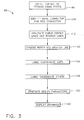
- FIG 3 is an exemplary embodiment of an information flow diagram 80 illustrating process steps executed by processing system 10 under the control of program 30 (shown in Figure 1).
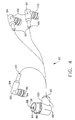
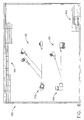
- Figures 4 and 5 illustrate exemplary outputs generated with program 30.
- Executing information flow diagram 80 with processing system 10 under the control of program 30 generates a two-dimensional electronically modeled aircraft engine harness 82 from a three-dimensionally defined harness, such as aircraft engine harness 40 (shown in Figure 2).
- connector fittings 84 are defined 86 using a plurality of connector fitting ports 88 as shown in Figure 4. Specifically, each connector fitting 84 is defined 86 in terms of a connector port 90, a direction port 92, a free port 94, and a key port 96. Each connector fitting 84 is defined using (X, Y, Z) coordinates.
- each connector port 90 identifies a connector fitting connect point 76 (shown in Figure 2).
- Each direction port 92 identifies an intersection between connector fitting receptacle portion center axis of symmetry 74 (shown in Figure 2) and connector fitting body portion axis of symmetry 78 (shown in Figure 2).
- Each free port 94 identifies a connector fitting receptacle portion 72 (shown in Figure 2), and each key port 96 identifies the connector fitting receptacle portion key.
- a base connector 100 and an end connector 102 are identified 104 and then defined 86 using connector fitting ports 88. More specifically, connector fitting ports 90, 92, 94, and 96 are used to identify portions of base connector 100 and end connector 102 that are respectively identical to those connector fitting portions identified above with the same connector fitting port. Accordingly, base connector 100, end connector 102, and each connector fitting 84 are defined 86 using four connector fitting ports 88.
- a cable center line 108 and branch lines 110 are generated 112 as shown in Figure 5.
- Cable center line 108 extends linearly between base connector 100 and end connector 102
- branch lines 110 extend linearly between cable center line 108 and each respective connector fitting 84.
- One branch line 110 is then chosen 120 to be a reference branch line.
- branch line 110 is chosen 120, an X and Y plane are established and a reference coordinate axes C sys is labeled 124 at base connector 100.
- coordinate points A, B, C, D, E, F, G, H, J, K, L, M, N, and P are labeled 128 representing each connector fitting port 88 previously defined and branch points G and L representing an intersection between each branch line 110 and cable center line 108.
- Design parameters, described in more detail below, for aircraft engine harness 82 are then generated 130. Additionally, a two-dimensional electronically modeled aircraft harness drawing (not shown in Figures 4 and 5) is generated 132. More specifically, program 30 converts a three-dimensionally defined harness 40 into a two-dimensional stick form drawing that represents harness 40. Converting harness 40 into a two-dimensional stick form drawing is sometimes referred to as unfolding. Program 30 facilitates defining harness 40 quickly, reliably, and in a condition that is suitable for manufacturing and inspection.
- the design parameters and drawings are then displayed 140.
- the design parameters are displayed 140 in a tabular format (not shown in Figures 4 and 5) and are included and displayed 140 with the drawings.
- Figure 6 is an exemplary output 150 generated using modeling system 30 (shown in Figure 3) and illustrating two-dimensional electronically modeled aircraft harness 82.
- harness 82 is illustrated in a first orientation 152 viewed along an X-Y plane, and a second orientation 154 along a Z-X plane.
- harness 82 may be rotated to any other orientation.
- output 150 also includes a reference table 160 and a title box 162.
- Figure 7 is an exemplary reference table 160 generated by processing system 10 (shown in Figure 1) under the control of program 30 (shown in Figure 1) and in accordance with the method shown in Figure 2.
- Reference table 160 includes a plurality of data portions 163 utilized for manufacturing and inspection. More specifically, reference table data portions 163 enable a harness (not shown) to be manufactured from a two-dimensional electronically modeled aircraft engine harness, such as harness 82 (shown in Figure 6).
- a length chart portion 164 provides various lengths 166 of segments 168 of harness 82 (shown in Figure 6). More specifically, length chart portion 164 provides ordinate lengths along harness cable center line 108 and each branch line 110. Harness segments 168 are defined using coordinate points A, B, C, D, E, F, G, H, J, K, L, M, N, and P, and branch points G and L.
- a segment length chart portion 170 provides lengths 172 of harness 82 between harness branches 110. Segment length chart portion 170 also provides segment diameters 174 of portions 176 of harness 82 along harness cable center line 108 and each branch line. Harness portions 176 are defined using coordinate points A, B, C, D, E, F, G, H, J, K, L, M, N, and P, and branch points G and L. Diameters 174 are determined using a diameter calculation program (not shown).
- a branch angle chart portion 180 provides branch breakout angles 182 (illustrated in Figure 5) of various defined portions 184 of harness 82. Portions 184 are defined using coordinate points A, B, C, D, E, F, G, H, J, K, L, M, N, and P, and branch points G and L. In one embodiment, breakout angles 182 are in increments of approximately fifteen degrees, and each breakout angle 182 is between approximately thirty and ninety degrees.
- a turn table angle chart portion 190 defines a turn table angle 192 (illustrated in Figure 4) between two planes 194 defined with adjacent harness branches 110.
- the planes intersect in a straight line (not shown) that is coincident with centerlines (not shown) of each straight length common to both angles.
- Turn table angle 192 is defined between the straight length and a previous branch breakout angle 182, and is measured in a counter-clockwise direction from a plane 194 defined by a previous branch 110.
- a base and true angle chart portion 200 defines a base angle 202 (measured relative to X-Y plane 154 and to branches 204, and measured in a counter-clockwise direction from the X-axis).
- a true angle 206 is measured from X-Y plane 154.
- a fitting and master key-way turn table angle portion 210 defines a turn table angle 212 using a straight line (not shown) that is coincident with an intersection between a first three point plane (not shown) and a second three point plane.
- Turn table angle 212 is defined between the straight line and a previous angle 214, and measured in a counter-clockwise direction from the plane of previous angle 214.
- the modeling system generates a two-dimensional electronic model from a three-dimensionally defined harness. Furthermore, the modeling system facilitates unfolding a three-dimensionally defined harness in a shorter time duration than is possible with known harness unfolding methods. Accordingly, the modeling system provides a definition of a harness that is the same in a manufactured condition as in a designed condition. As a result, the modeling system produces two-dimensional electronic models for manufacturing in a cost-effective and reliable manner.
Landscapes
- Engineering & Computer Science (AREA)
- Physics & Mathematics (AREA)
- Geometry (AREA)
- General Physics & Mathematics (AREA)
- Theoretical Computer Science (AREA)
- Mathematical Optimization (AREA)
- Computational Mathematics (AREA)
- Mathematical Analysis (AREA)
- Aviation & Aerospace Engineering (AREA)
- Pure & Applied Mathematics (AREA)
- Computer Hardware Design (AREA)
- Evolutionary Computation (AREA)
- General Engineering & Computer Science (AREA)
- Automation & Control Theory (AREA)
- Processing Or Creating Images (AREA)
- Installation Of Indoor Wiring (AREA)
Applications Claiming Priority (4)
| Application Number | Priority Date | Filing Date | Title |
|---|---|---|---|
| US780814 | 1997-01-09 | ||
| US24156000P | 2000-10-19 | 2000-10-19 | |
| US241560P | 2000-10-19 | ||
| US09/780,814 US7024341B2 (en) | 2000-10-19 | 2001-02-09 | Methods and apparatus for electronically modeling aircraft engine harnesses |
Publications (2)
| Publication Number | Publication Date |
|---|---|
| EP1205862A2 true EP1205862A2 (fr) | 2002-05-15 |
| EP1205862A3 EP1205862A3 (fr) | 2003-09-03 |
Family
ID=26934394
Family Applications (1)
| Application Number | Title | Priority Date | Filing Date |
|---|---|---|---|
| EP01308663A Withdrawn EP1205862A3 (fr) | 2000-10-19 | 2001-10-11 | Procédé et dispositif de modélisation électronique de câblage pour engines d'avion |
Country Status (3)
| Country | Link |
|---|---|
| US (1) | US7024341B2 (fr) |
| EP (1) | EP1205862A3 (fr) |
| JP (1) | JP2002178998A (fr) |
Cited By (3)
| Publication number | Priority date | Publication date | Assignee | Title |
|---|---|---|---|---|
| FR2925428A1 (fr) * | 2007-12-21 | 2009-06-26 | Valeo Systemes De Liaison Sa | Procede de modelisation d'un cablage electrique pour vehicule, procede de fabrication du cablage |
| EP2410536A1 (fr) * | 2010-07-23 | 2012-01-25 | Leoni Wiring Systems France | Procédé de modélisation d'un câblage électrique susceptible d'adopter différentes configurations |
| FR3023634A1 (fr) * | 2014-07-11 | 2016-01-15 | Dassault Aviat | Systeme informatise de conception du routage tridimensionnel de cables electrique dans un systeme electrique, et procede de conception correspondant |
Families Citing this family (11)
| Publication number | Priority date | Publication date | Assignee | Title |
|---|---|---|---|---|
| US7107197B1 (en) * | 2001-01-26 | 2006-09-12 | Mentor Graphics Corporation | Wiring harness data systems |
| DE102005028103A1 (de) * | 2005-06-16 | 2006-12-21 | Flexilution Gmbh | Verfahren zur Darstellung flexibler längenerstreckter Volumenobjekte |
| US7793250B2 (en) * | 2005-12-19 | 2010-09-07 | The Boeing Company | Topology-driven apparatus, method and computer program product for developing a wiring design |
| JP2007272397A (ja) * | 2006-03-30 | 2007-10-18 | Toshiba Corp | 設計支援装置、設計支援方法、及びプログラム |
| US20080234850A1 (en) * | 2007-03-19 | 2008-09-25 | Bowling William C | Model based definition installation and assembly drawing process |
| KR101061188B1 (ko) | 2008-12-30 | 2011-08-31 | 재단법인 국방기술품질원 | 항공기 면적곡선 분석 방법 |
| CN103399988B (zh) * | 2013-07-15 | 2016-04-13 | 中国商用飞机有限责任公司 | 对飞机线束的安装状况以样板进行模拟的方法以及其样板 |
| US10635777B2 (en) * | 2016-02-16 | 2020-04-28 | Bayerische Motoren Werke Aktiengesellschaft | Method for generating and using a two-dimensional drawing having three-dimensional orientation information |
| US11893320B2 (en) | 2021-11-18 | 2024-02-06 | Dassault Systemes Solidworks Corporation | Method for backshell components in 3D routing harness and flattening route harness |
| US12033298B2 (en) * | 2021-11-18 | 2024-07-09 | Dassault Systemes Solidworks Corporation | Method for maintaining 3D orientation of route segments and components in route harness flattening |
| CN118410652B (zh) * | 2024-07-01 | 2024-08-27 | 中国航空工业集团公司沈阳飞机设计研究所 | 一种飞机机载线束电磁样机建模方法 |
Family Cites Families (19)
| Publication number | Priority date | Publication date | Assignee | Title |
|---|---|---|---|---|
| US3867616A (en) | 1968-09-03 | 1975-02-18 | Badger Co | Automated designing |
| US3574467A (en) * | 1969-07-09 | 1971-04-13 | Nasa | Method and apparatus for aligning a laser beam projector |
| US3781552A (en) * | 1972-08-02 | 1973-12-25 | K Kadrmas | Self-calibrating multiple field of view telescope for remote atmospheric electromagnetic probing and data acquisition |
| JPS6488881A (en) * | 1987-08-24 | 1989-04-03 | Ibm | Generation of assembling screen |
| US4928233A (en) | 1987-08-24 | 1990-05-22 | International Business Machines | System for providing three dimensional object descriptions |
| US5260883A (en) | 1988-07-21 | 1993-11-09 | Daniel Flow Products, Inc. | Interactive data entry system and method for the design, engineering and manufacture of meter tubes |
| US5293479A (en) | 1991-07-08 | 1994-03-08 | Quintero Smith Incorporated | Design tool and method for preparing parametric assemblies |
| US5680525A (en) | 1991-08-08 | 1997-10-21 | Hitachi, Ltd. | Three-dimensional graphic system with an editor for generating a textrue mapping image |
| EP0537030B1 (fr) | 1991-10-11 | 1997-09-17 | Canon Kabushiki Kaisha | Méthode de traitement de caractères ou de données graphiques |
| US5506950A (en) | 1992-12-18 | 1996-04-09 | Computervision Corporation | Method and apparatus for producing a three dimensional representation of a wire harness into a two dimensional presentation |
| JP3201156B2 (ja) | 1993-08-30 | 2001-08-20 | トヨタ自動車株式会社 | 設計を支援する方法と装置 |
| JP3307498B2 (ja) | 1994-03-18 | 2002-07-24 | 富士通株式会社 | 図形描画装置及びその方法 |
| US5517428A (en) | 1994-05-02 | 1996-05-14 | Williams; David | Optimizing a piping system |
| US5504687A (en) | 1994-11-22 | 1996-04-02 | Vescor Corporation | Apparatus for automated machinery component selection |
| US5825464A (en) * | 1997-01-03 | 1998-10-20 | Lockheed Corp | Calibration system and method for lidar systems |
| US6268871B1 (en) | 1997-04-30 | 2001-07-31 | Silicon Graphics, Inc. | Generating a curve for computer graphics through points residing on underlying geometries in a three dimensional space |
| DE69832441D1 (de) | 1997-07-07 | 2005-12-29 | J S T Mfg Co Ltd | Informationsverarbeitungsgerät für Kabelbäume |
| JP2000011778A (ja) * | 1998-06-22 | 2000-01-14 | Sumitomo Wiring Syst Ltd | ワイヤハーネス用電線の切断寸法設定方法 |
| US6608677B1 (en) * | 1998-11-09 | 2003-08-19 | Brookhaven Science Associates Llc | Mini-lidar sensor for the remote stand-off sensing of chemical/biological substances and method for sensing same |
-
2001
- 2001-02-09 US US09/780,814 patent/US7024341B2/en not_active Expired - Fee Related
- 2001-10-11 EP EP01308663A patent/EP1205862A3/fr not_active Withdrawn
- 2001-10-18 JP JP2001320054A patent/JP2002178998A/ja active Pending
Non-Patent Citations (2)
| Title |
|---|
| WAKELY C.J.; SHARP M.J.: "Vehicle wiring harness design and manufacture", THIRD INTERNATIONAL CONFERENCE: CAD-CAM-CAE INTEGRATION TECHNOLOGIES IN THE AUTOMOTIVE INDUSTRY, 1988, TORINO, ITALY, pages 445 - 464 * |
| WAKELY, C.J; SHARP, M.J.: "Vehicle Wiring Harness Design & Manufacture", THIRD INTERNATIONAL CONFERENCE: CAD-CAM-CAE INTEGRATION TECHNOLOGIES IN THE AUTOMOTIVE INDUSTRY, 1988, pages 445 - 464 |
Cited By (5)
| Publication number | Priority date | Publication date | Assignee | Title |
|---|---|---|---|---|
| FR2925428A1 (fr) * | 2007-12-21 | 2009-06-26 | Valeo Systemes De Liaison Sa | Procede de modelisation d'un cablage electrique pour vehicule, procede de fabrication du cablage |
| WO2009081058A1 (fr) * | 2007-12-21 | 2009-07-02 | Leoni Wiring Systems France | Procede de modelisation d'un cablage electrique pour vehicule, procede de fabrication du cablage |
| EP2410536A1 (fr) * | 2010-07-23 | 2012-01-25 | Leoni Wiring Systems France | Procédé de modélisation d'un câblage électrique susceptible d'adopter différentes configurations |
| FR2962954A1 (fr) * | 2010-07-23 | 2012-01-27 | Leoni Wiring Systems France | Procede de modelisation d'un cablage electrique susceptible d'adopter differentes configurations |
| FR3023634A1 (fr) * | 2014-07-11 | 2016-01-15 | Dassault Aviat | Systeme informatise de conception du routage tridimensionnel de cables electrique dans un systeme electrique, et procede de conception correspondant |
Also Published As
| Publication number | Publication date |
|---|---|
| EP1205862A3 (fr) | 2003-09-03 |
| US20020111778A1 (en) | 2002-08-15 |
| JP2002178998A (ja) | 2002-06-26 |
| US7024341B2 (en) | 2006-04-04 |
Similar Documents
| Publication | Publication Date | Title |
|---|---|---|
| US7024341B2 (en) | Methods and apparatus for electronically modeling aircraft engine harnesses | |
| CN104346830B (zh) | 在三维场景中设计连接第一点到第二点的路径 | |
| EP0304864B1 (fr) | Méthode pour produire des instructions de construction pour des assemblages tridimensionnels | |
| WO2007068674A1 (fr) | Representation de faisceau de cables orthogonale en deux dimensions | |
| KR20090064244A (ko) | 혼합현실 시스템 및 그 구현 방법 | |
| US20090222121A1 (en) | Enhanced flattening for cable and wiring harnesses in computer-aided design drawings | |
| Spitz et al. | Accessibility analysis using computer graphics hardware | |
| US20070255544A1 (en) | Two-dimensional orthogonal wire harness representation | |
| US7403829B2 (en) | Estimating method and apparatus and estimating program of wire harness and recording medium thereof | |
| US20100070243A1 (en) | Wire Harness Unfolding | |
| JP2003132102A (ja) | ワイヤーハーネスの設計方法 | |
| CN111414508B (zh) | 一种在设计模型中搜索并实现可视化的方法及终端 | |
| US6963825B1 (en) | Outline extracting apparatus and method and computer readable memory medium | |
| Prieto et al. | A novel method for early formal developments using computer aided design and rapid prototyping technology | |
| JP7239302B2 (ja) | 配索状態提示方法および配索状態提示装置 | |
| Du et al. | Configuration modeling and experimental verification with 3D laser scanning technology for a constrained elastica cable | |
| CN1099645C (zh) | 点群数据的曲面变换方法 | |
| JPH0973476A (ja) | 三次元形状情報入力装置 | |
| US20030184567A1 (en) | Information processing method and apparatus | |
| KR100610756B1 (ko) | 수치 데이터에 의해 조인트의 상태가 표시되는 컴퓨터를이용한 해석 및 설계용 그래픽 표시장치 | |
| JP2026061564A (ja) | 教師データ生成装置、教師データ生成方法、教師データ生成プログラム、点群補完装置、点群補完方法、及び点群補完プログラム | |
| Inui et al. | Accessibility map for assisting cutter posture determination in five-axis mold machining | |
| KR20030073391A (ko) | 와이어링 하네스 설계도면 생성 시스템 및 그 방법 | |
| Inui et al. | Clearance measurement of 3D objects using accessibility cone | |
| Chipperfield et al. | Modeling of hydraulic hose paths |
Legal Events
| Date | Code | Title | Description |
|---|---|---|---|
| PUAI | Public reference made under article 153(3) epc to a published international application that has entered the european phase |
Free format text: ORIGINAL CODE: 0009012 |
|
| AK | Designated contracting states |
Kind code of ref document: A2 Designated state(s): AT BE CH CY DE DK ES FI FR GB GR IE IT LI LU MC NL PT SE TR |
|
| AX | Request for extension of the european patent |
Free format text: AL;LT;LV;MK;RO;SI |
|
| PUAL | Search report despatched |
Free format text: ORIGINAL CODE: 0009013 |
|
| AK | Designated contracting states |
Kind code of ref document: A3 Designated state(s): AT BE CH CY DE DK ES FI FR GB GR IE IT LI LU MC NL PT SE TR |
|
| AX | Request for extension of the european patent |
Extension state: AL LT LV MK RO SI |
|
| 17P | Request for examination filed |
Effective date: 20040303 |
|
| 17Q | First examination report despatched |
Effective date: 20040401 |
|
| AKX | Designation fees paid |
Designated state(s): DE FR GB IT |
|
| 17Q | First examination report despatched |
Effective date: 20040401 |
|
| STAA | Information on the status of an ep patent application or granted ep patent |
Free format text: STATUS: THE APPLICATION IS DEEMED TO BE WITHDRAWN |
|
| 18D | Application deemed to be withdrawn |
Effective date: 20140501 |