EP1205947A1 - Dispositif de traversée de cloison pour cable electrique haute tension - Google Patents
Dispositif de traversée de cloison pour cable electrique haute tension Download PDFInfo
- Publication number
- EP1205947A1 EP1205947A1 EP01402919A EP01402919A EP1205947A1 EP 1205947 A1 EP1205947 A1 EP 1205947A1 EP 01402919 A EP01402919 A EP 01402919A EP 01402919 A EP01402919 A EP 01402919A EP 1205947 A1 EP1205947 A1 EP 1205947A1
- Authority
- EP
- European Patent Office
- Prior art keywords
- cable
- primary
- partition
- insulating
- bulkhead
- Prior art date
- Legal status (The legal status is an assumption and is not a legal conclusion. Google has not performed a legal analysis and makes no representation as to the accuracy of the status listed.)
- Granted
Links
Images


Classifications
-
- H—ELECTRICITY
- H01—ELECTRIC ELEMENTS
- H01B—CABLES; CONDUCTORS; INSULATORS; SELECTION OF MATERIALS FOR THEIR CONDUCTIVE, INSULATING OR DIELECTRIC PROPERTIES
- H01B17/00—Insulators or insulating bodies characterised by their form
- H01B17/26—Lead-in insulators; Lead-through insulators
- H01B17/30—Sealing
- H01B17/303—Sealing of leads to lead-through insulators
- H01B17/308—Sealing of leads to lead-through insulators by compressing packing material
Definitions
- the technical field of the present invention is that of connectors for high electrical currents voltage of the order of fifty thousand volts and capable of go up to a hundred thousand volts (without this value being limiting).
- Another achievement is to try to create a dielectric continuity by interposing between the material insulator of the base and the metal partition of the grease or oil, to improve the dielectric strength by avoiding any air pocket between these different elements. Surface breakdowns, occurring at the junction and along the insulators, are thus minimized, because of the disappearance of air pockets between these different materials.
- the maximum improvement that such devices is a tensile strength increased by 20% only.
- the object of the invention is to overcome these disadvantages by proposing a crossing device partition for which the shielding protection is kept until the crossing of the partition and for which the part emerging beyond the partition is weak dimension (typically less than a centimeter, even for voltages of the order of one hundred thousand volts).
- Another object of the present invention is to achieve a high voltage cable connection device can be designed according to the same principle as the device bulkhead crossing.
- the present invention relates to a bulkhead crossing device, in particular of the type metal partition for high coaxial electric cable voltage, including an insulating base fixed on the partition.
- the latter has an upstream end (conventionally designating the air line side) and a downstream end (conventionally designating the line side isolated), each projecting on either side of. the partition, said insulating base being able to be traversed right through, without junction, by the conductive core of a cable.
- This device also includes means for primary mechanical fasteners located on the downstream end of the base and intended to cooperate with fixing means secondary mechanics fixed on the sheathed part of the cable.
- This device is characterized in that the conductive core of the cable is, at the crossing of the partition, electrically isolated from the partition by means electrical insulation tablets.
- the compression ratio of the insulation means electric is preferably at least 30%.
- the compressed electrical insulation means are located between the upstream end emerging from the insulating base and the partition, as well as at the level of the central body of the insulating base between the conductive core of the cable and the insulating base.
- This bulkhead crossing device may include a thin insulating layer of the sheet type covering the metal partition on the side of the upstream end of the base insulating.
- the end upstream emerging from the insulating base is provided with a collar capable of containing part of the means electrical insulation.
- the primary mechanical fastening means include a metal casing being suitable for the use of means screw nut type primers, to be fixed on the end downstream of the insulating base and to receive means secondary screw nut type intended to cooperate with secondary fastening means.
- the primary mechanical fastening means are electrically conductive and may include means of electrical connection cooperating with the partition.
- the secondary mechanical fastening means are also electrically conductive and connected electrically to the cable shield.
- the conductive core of the cable is able to cooperate with electrically conductive means of the ball type.
- This bulkhead crossing device comprises means insulation tablets consisting of materials of the type silicone sponge.
- this relates to a device for connecting high voltage cables including an insulating enclosure primary and a secondary insulating enclosure, the enclosure primary insulator and the secondary insulating enclosure being mounted respectively on a primary conductive core of a first cable and on a secondary conductive core a second cable.
- the primary insulating enclosure and the secondary insulating enclosure are capable of being respectively enveloped by recovery means primary shielding and shielding recovery means secondary, these means of recovery of primary armor and secondary being in contact and integral with each other.
- This device is characterized in that the conductive souls primary and secondary as well as the connecting element are electrically isolated from the recovery means primary and secondary shielding using means electrical insulation tablets.
- This device using insulators has the advantage of sealing electric between two conductive elements or not, in filling all the roughness of the interfaces which allows considerably reduce the breakdown phenomenon due to surface discontinuities.
- Another advantage of the invention is to present a device for which, from a certain rate of compression applied, the phenomenon of surface breakdown disappears in favor of a breakdown phenomenon in volume; compression then improves more and more sensitive to the dielectric strength on the surface of the insulation. Another advantage is that this technique adapts independently of the choice of materials ensuring dielectric junction and that it can adjust to the holding in desired voltage.
- the device which is the subject of the invention finally presents the advantage of greatly reducing manufacturing costs bulkhead devices by reducing the machining performed on insulators used in the art prior.
- the invention can be adapted so advantageous for obtaining a connection device for high voltage cables with a design based on same principle as that of the crossing device of partition whose advantages have been mentioned above.
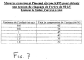
- Figure 7 shows a relative measurement table with material K495 from Keeling Rubber & Plastics Ltd corresponding to the values to be given to the thickness of this insulation depending on the compression ratio administered to it last so that it supports a breakdown voltage in surface of the order of 50 kVolts.
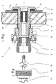
- This device (1) consists of an insulating base (5) of substantially cylindrical shape and of revolution, comprising three separate parts. We have everything first the central body (18), as well as two ends one upstream and the other downstream. This device can be adapted to any partition thickness by interposing a tube if necessary driver.
- a metal partition (2) intended to receive this insulating base (5) has a bore in which the latter may be introduced. Once in place, the insulating base is fixed, its central body (18) is then finding in the bore of the partition (2) and its ends protruding outside the bulkhead, the upstream end (14) on the air line side of the partition and the downstream end (15) on the other side.
- the upstream end (14) has a head allowing the base to take a support on the partition (2), while the downstream end (15) is cylindrical and of a diameter equal to that of the body central. This end is threaded and suitable for receiving primary mechanical fastening means (7,8,9).
- the mechanical fixing means primaries (7,8,9) consist of a ring internally threaded (9) representing primary means of the screw type nut and coming to be screwed on the downstream end (15), this ring (9) also having two threaded holes allowing using screws to fix secondary means (8) of the type screw nut which will be intended to cooperate with means of secondary mechanical fixing (11) integral with the cable. It is therefore the entire aforementioned device which will be crossed by the conductive core (12) of a cable (13). In indeed, the cable (13) will penetrate this device opening from end to end, without the conductive core of this cable is not in contact with some other part conductor of this device.
- the isolation of the soul (12) will be completed at the junction between the partition (2) and the upstream end (14) of the base by compressed insulation (4), which will prevent arcing that can spread from the hot spot representing the end of the cable core to the metal wall (2).
- the insulation of the core (12) will also be completed at the passage of the metal partition through the insulation tablet (10) in the form of a cylindrical cap for avoid a current return inside and along the body (18). In the absence of such means of insulation, the arc electric could join the metal part (9) in starting from the end of the core and passing through inside the body (18) to the downstream end (15).
- electrical insulation reinforcements will be carried out using electrical insulation means (4,10) which will be located in the places previously mentioned.
- This washer is interposed between the upstream end (14) of the base and the partition (2).
- This washer is made of a material compressible, which allows establishing a true electrical seal between the upstream end (14) and the partition (2).
- This end may have a flange (16) capable of ensuring better maintenance of the washer as well as an obstacle to its creep over time.
- This use of particularly soft compressible bodies allows the realization of an upstream end (14) of very small size.
- a cylindrical plug (10) drilled from end to end is also used for electrical sealing. Of the same way, the latter is compressed in a bore located inside the central body (18), and is capable of receive and be traversed by the conductive core (12) cable (13).
- the cable is broken down into two parts. First place the conductive core (12), the end of which is located at the upstream end (14) of the base once the cable is positioned on the device, and secondly the sheathed part having a shielding around the cable. It should be noted that the conductive core (12) can be connected to a conductive ball (17) like this is shown in Figure 3. This will have the effect to improve the form factor, therefore to reduce the fields avoiding peak effects, which will as a direct consequence of increasing the tensile strength of the connector.
- the cable also has fixing means secondary mechanics (11) intended to cooperate with the primary mechanical fastening means (7,8,9). They located at the junction of the core with the part sheathed in the cable and are connected to its shielding. These means include in particular a threaded part (11) thus allowing the cable to be fixed to the base during the cooperation of this party (11) with the means secondary (8) of the screw nut type cooperating with the downstream end (15) of the base (5).
- connection means electric located on the mechanical fixing means primers can consist of a metal ring (6) in contact with the partition (2) and thus ensuring the transmission of the contact to the cable shield (13).
- the application of the device described above is not not limit the transition between a coaxial cable and a air line, but can also be applied to other electrical components such as spark gaps, high voltage and low inductance distributors for coaxial cables, or at the high cable connection voltage.
- This bulkhead crossing device can also be used to make a high probe voltage and high frequency and make measurements referenced to a conductive floor plan. The measurement can be taken almost at the cable entry and therefore directly below its characteristic impedance without inserting inductance corresponding to electrical lengths usually necessary to avoid breakdowns.
- FIG. 6 on. can see a high voltage cable connection device using the same type of compressed insulation means for electrically seal between the different components.
- This device includes two speakers insulating, one primary (19a) and the other secondary (19b). Each of these insulating enclosures (19a) and (19b) is respectively mounted on the primary conductive core (20a) of a first cable (27a) and the conductive core secondary (20b) of a second cable (27b). These cables first and second are of course the ones that require to be connected to each other using this device according to the invention.
- the two conductive souls (20a) and (20b) will therefore have to be electrically connected, this which will be achieved by an electrical connection element (21), which can in particular be of the ball type in which souls are likely to plug in.
- insulating enclosures can be designed in such a way that each can receive a half ball at its end.
- These primary (19a) and secondary (19b) insulating enclosures are respectively wrapped by return means primary (22a, 23a) and secondary (22b, 23b) shielding; these primary armor recovery means and these means of secondary shielding are in contact and interdependent, each being electrically connected with the shield (24a) or (24b) of the cable with which it cooperates.
- each of these means is broken down into two separate parts.
- a first part (22a) or (22b) can have a function similar to that described for the means primary mechanical fixing (7,8,9) of the bulkhead shown in Figure 1.
- the second part (23a) or (23b) can then in the configuration presented to be assimilated to the partition metallic (2) of this same crossing device of partition.
- it is therefore a high voltage cable connection using for its production of two devices assembled with each other, these devices being substantially similar to those described as bulkhead crossing devices.
- Their assembly is done in this preferred embodiment by through the parts (23a) and (23b) of the means of recovery of primary and secondary shielding, assembly can be ensured by threading these parts making them united and in contact with each other.
- the high voltage cable connection includes means for resumption of primary shielding (22a, 23a) and secondary (22b, 23b) which must be electrically isolated from souls primary (20a) and secondary (20b) conductors as well as of the electrical connection element (21).
- primary shielding 22a, 23a
- secondary 22b, 23b
- electrical insulation 25a, 25b, 26
- These means of insulation electric tablets 25a, 25b, 26) are also two different places. First between each insulating enclosure (19a) or (19b) and the conductive core of the cable with which it cooperates.
- This part of the means electrical insulation tablets therefore takes, as in the bulkhead device, the shape of a plug cylindrical having the same properties as that described like the cylindrical plug (10) of the bulkhead and being compressed in the same way.
- the second part of these means of electrical insulation tablets is between the two ends opposite the primary (19a) and secondary (19b) insulating enclosures.
- This part takes the form of a washer (26) placed around of the electrical connection element (21), which is in the occurrence in the embodiment describes a ball conductive.
- This washer (26) is also assimilable to the washer (4) of the bulkhead crossing device shown in Figure 1, showing the same characteristics than the latter. Compression is here produced by clamping between the recovery means primary shielding (22a, 23a) and the means for resuming shielding (22b, 23b).
- this tightening can be carried out by screwing the parts (23a) and (23b) between them, the compression ratios being respected compared to those who will be described for the washer (4) of the bulkhead crossing device.
- These compressed electrical insulation means (25a, 25b, 26) will then prevent the formation of electric arcs between the various conductive elements of this device.
- the compression mechanism of the insulation means electrical (4.10) in the feed-through device partition is as follows:
- the washer (4) is preferentially intended to be housed in the flange (16) of the base (5) and is compressed by clamping between the upstream end (14) emerging from the base (5) and the partition (2). This tightening is carried out by the displacement towards the partition of the rings (6,9) thus pressing the head of the end (14) against this partition (2).
- a sheet insulator (3) can be interposed between the partition and the upstream end (14).
- the cylindrical plug (10) is able to be housed in the central body (18), and is then compressed in two successive stages. In one first, the cylindrical plug (10) undergoes a compression during its positioning in the bore of the central body (18), due to the dimensions of its diameter outside which is slightly less than the diameter of the bore of the central body (18). Secondly, it is compressed by force fitting the conductive core (12) of the cable in the clean bore of the plug, produced by drilling before mounting. Indeed, this drilling will made with a suitable drill so as to result in a diameter of the bore slightly smaller than the diameter of the conductive core (12) of the cable. This way of compressing the insulator, being of course only one example among others, will then lead to the desired compression at from precise parameters for dimensioning the elements insulators used and that the skilled person will be able to determine.
- the cable core can cross the plug without degrading it, it is better to attach a rounded, smooth and conductive tip (not shown in the figure) welded to the end of the core.
- the reference material used here selected for its mechanical performance and insulation during the tests, is a silicone sponge closed cells, known as K495, marketed by Keeling Rubber & Plastics Ltd.
- This 60% barrier is the one noted concerning the mostly tested product, K495, but may fluctuate by a few percent depending on whether we use other similar silicone products or other products. It is as well as we were able to raise thresholds ranging from around 55% at around 65%.
- the K495, very soft material, has been placed in the collar (16) in the form of a washer (4).
- Type insulation Siloprene could not in this case replace K495, as far as the compression needed to get electrical tightness could lead to rupture of the device.
- the Siloprene was placed in the form of cylindrical plug in a bore of the central body (18), the K495 being too soft to penetrate the bore of the body about half the diameter.
- the connector had protruding upstream end (14) beyond the partition (2) by a distance less than 7 mm for a voltage of fifty thousand volts, and less than 10 mm for a voltage of one hundred thousand volts.
- another preferred embodiment of the invention relates to a device for connecting high voltage cables.
Landscapes
- Cable Accessories (AREA)
- Insulators (AREA)
- Installation Of Indoor Wiring (AREA)
Abstract
Description
- la figure 1 représente une vue en coupe du dispositif de traversée de cloison fixé sur une cloison métallique ;
- la figure 2 représente une vue en plan d'un câble destiné à être inséré dans le dispositif de traversée de cloison ;
- la figure 3 représente une vue en coupe du dispositif de traversée de cloison avec l'âme conductrice du câble connectée à une boule.
- la figure 4 représente une vue en coupe du dispositif de traversée de cloison en coopération avec un éclateur pour ligne coaxiale.
- la figure 5 représente une vue en coupe du dispositif de traversée de cloison en coopération avec un répartiteur haute tension faible inductance pour câbles coaxiaux.
- La figure 6 représente un vue en coupe longitudinale d'un dispositif de raccordement de. câbles haute tension selon la présente invention.
- longueur de l'extrémité amont (14) à la pièce (8) : 80 mm
- diamètre du corps (18) : 25 mm
- diamètre de l'extrémité amont (14) : 70 mm
- dépassement de l'extrémité amont au-delà de la cloison : < 10 mm
Claims (18)
- Dispositif (1) de traversée de cloison (2) notamment du type cloison métallique pour câble électrique coaxial haute tension, comprenant une embase isolante (5) fixée sur la cloison, l'embase ayant un corps central (18), une extrémité amont (14) et une extrémité aval (15), ces dernières faisant saillie respectivement de part et d'autre de la cloison, ladite embase isolante (5) étant apte à être traversée par l'âme conductrice (12) d'un câble (13), et des moyens de fixation mécanique primaires (7,8,9) situés sur l'extrémité aval de l'embase et destinés à coopérer avec des moyens de fixation mécanique secondaires (11) fixés sur la partie gainée du câble (13), caractérisé en ce que l'âme conductrice (12) du câble (13) est électriquement isolée de la cloison (2) à l'aide de moyens d'isolation électrique (4,10) comprimés ;
- Dispositif de traversée de cloison selon la revendication 1, caractérisé en ce que le taux de compression des moyens d'isolation électrique (4,10) est au minimum de 30% ;
- Dispositif de traversée de cloison selon la revendication 1 ou la revendication 2, caractérisé en ce que les moyens d'isolation électrique (4,10) comprimés sont positionnés entre l'extrémité amont débouchant (14) de l'embase isolante (5) et la cloison (2), ainsi qu'au niveau du corps central (18) de l'embase isolante (5) entre l'âme conductrice (12) du câble et ladite embase isolante (5) ;
- Dispositif de traversée de cloison selon l'une quelconque des revendications précédentes, caractérisé en ce que la cloison (2) est recouverte du côté de l'extrémité amont
- Dispositif de traversée de cloison selon l'une quelconque des revendications précédentes, caractérisé en ce que l'extrémité amont débouchant (14) de l'embase isolante présente une collerette (16) apte à contenir une partie des moyens d'isolation électrique (4,10);
- Dispositif de traversée de cloison selon l'une quelconque des revendications précédentes, caractérisé en ce que les moyens de fixation mécanique primaires comprennent une enveloppe métallique (9) étant apte à l'aide de moyens primaires du type vis écrou, à se fixer sur l'extrémité aval (15) de l'embase isolante (5), et à recevoir des moyens secondaires (8) du type vis écrou destinés à coopérer avec les moyens de fixation secondaires ;
- Dispositif de traversée de cloison selon l'une quelconque des revendications précédentes, caractérisé en ce que les moyens de fixation mécanique primaires (7,8,9) sont électriquement conducteurs et comprennent des moyens de raccordement électrique (6) coopérant avec la cloison (2), et que les moyens de fixation mécanique secondaires (11) sont également électriquement conducteurs et raccordés électriquement au blindage du câble ;
- Dispositif de traversée de cloison selon l'une quelconque des revendications précédentes, caractérisé en ce que l'extrémité amont débouchant (14) de l'embase isolante est apte à coopérer avec des moyens conducteurs d'électricité du type boule (17) ;
- Dispositif de traversée de cloison selon l'une quelconque des revendications précédentes, caractérisé en ce que les moyens d'isolation (4,10) comprimés sont réalisées en matériaux du type éponge silicone ;
- Dispositif de traversée de cloison selon l'une quelconque des revendications précédentes, caractérisé en ce que la partie des moyens d'isolation (4,10) se trouvant entre l'âme conductrice (12) du câble (13) et l'embase isolante (5) est un bouchon cylindrique (10) muni d'un alésage débouchant de part et d'autre de la pièce dont la compression est partiellement réalisée par l'emmanchement à force de l'âme conductrice (12) du câble dans cet alésage ;
- Dispositif de traversée de cloison selon l'une quelconque des revendications précédentes, caractérisé en ce que la partie des moyens d'isolation (4,10) se trouvant entre l'extrémité amont débouchant (14) de l'embase isolante (5) et la cloison (2) est une rondelle (4) dont la compression est réalisée par le serrage du dispositif (1) sur la cloison (2) ;
- Dispositif de raccordement de câbles haute tension comprenant une enceinte isolante primaire (19a) et une enceinte isolante secondaire (19b), l'enceinte isolante primaire (19a) et l'enceinte isolante secondaire (19b) étant. montées respectivement sur une âme conductrice primaire (20a) d'un premier câble (27a) et sur une âme conductrice secondaire (20b) d'un second câble (27b), ces deux âmes conductrices étant destinées à être reliées par l'intermédiaire d'un élément de connexion électrique (21), l'enceinte isolante primaire (19a) et l'enceinte isolante secondaire (19b) étant aptes à être enveloppées par respectivement des moyens de reprise de blindage primaires (22a,23a) et des moyens de reprise de blindage secondaires (22b,23b), ces moyens de reprises de blindages primaires et secondaires en contact étant solidaires entre eux, caractérisé en ce que les âmes conductrices primaire (20a) et secondaire (20b) ainsi que l'élément de connexion électrique (21) sont électriquement isolés des moyens de reprise de blindage primaires (22a,23a) et secondaires (22B,23b) à l'aide de moyens d'isolation électriques comprimés (25a,25b,26) ;
- Dispositif de raccordement de câbles haute tension selon la revendication 12, caractérisé en ce que le taux de compression des moyens d'isolation électrique (25a,25b,26) est au minimum de 30% ;
- Dispositif de raccordement de câbles haute tension selon la revendication 12 ou la revendication 13, caractérisé en ce que les moyens d'isolation électrique (25a,25b,26) comprimés sont positionnés entre l'enceinte primaire (19a) et l'enceinte secondaire (19b), ainsi qu'entre chacune des âmes conductrices (20a,20b) et l'enceinte isolante (19a,19b) avec laquelle elle coopère ;
- Dispositif de raccordement de câbles selon l'une quelconque des revendications 12 à 14, caractérisé en ce que l'élément de connexion électrique (21) est du type boule ;
- Dispositif de raccordement de câbles selon l'une quelconque des revendications 12 à 15, caractérisé en ce que les moyens d'isolation (25a,25b,26) comprimés sont réalisées en matériaux du type éponge silicone ;
- Dispositif de raccordement de câbles selon l'une quelconque des revendications 12 à 16, caractérisé en ce que la partie des moyens d'isolation (25a,25b) se trouvant entre les âmes conductrices (20a,20b) et les enceintes isolantes (19a,19b) avec lesquelles elles coopèrent est constituée par des bouchons cylindriques (25a,25b) étant chacun muni d'un alésage débouchant de part et d'autre de la pièce et dont la compression est partiellement réalisée par l'emmanchement à force des âmes conductrices primaire (20a) et secondaire (20b) ;
- Dispositif de raccordement de câbles selon l'une quelconque des revendications 12 à 17, caractérisé en ce que la partie des moyens d'isolation (26) se trouvant entre l'enceinte isolante primaire (19a) et l'enceinte isolante secondaire (19b) est une rondelle (26) dont la compression est réalisée par un serrage entre les moyens de reprise de blindage primaires (22a,23a) et les moyens de reprise de blindage secondaires (22b,23b).
Applications Claiming Priority (2)
| Application Number | Priority Date | Filing Date | Title |
|---|---|---|---|
| FR0014594A FR2816771B1 (fr) | 2000-11-14 | 2000-11-14 | Dispositif de traversee de cloison |
| FR0014594 | 2000-11-14 |
Publications (2)
| Publication Number | Publication Date |
|---|---|
| EP1205947A1 true EP1205947A1 (fr) | 2002-05-15 |
| EP1205947B1 EP1205947B1 (fr) | 2005-08-31 |
Family
ID=8856396
Family Applications (1)
| Application Number | Title | Priority Date | Filing Date |
|---|---|---|---|
| EP01402919A Expired - Lifetime EP1205947B1 (fr) | 2000-11-14 | 2001-11-14 | Dispositif de traversée de cloison pour câble électrique haute tension |
Country Status (4)
| Country | Link |
|---|---|
| US (2) | US6617512B2 (fr) |
| EP (1) | EP1205947B1 (fr) |
| DE (1) | DE60113037T2 (fr) |
| FR (1) | FR2816771B1 (fr) |
Families Citing this family (5)
| Publication number | Priority date | Publication date | Assignee | Title |
|---|---|---|---|---|
| US7014502B2 (en) * | 2003-04-04 | 2006-03-21 | Anlynk Wireless, Llc | RF feedthrough coaxial connector for wireless communications in hazardous environments |
| US7355130B2 (en) * | 2004-04-09 | 2008-04-08 | Siemens Information And Communication Networks, Inc. | Cable sealing device |
| FR2923954B1 (fr) * | 2007-11-20 | 2010-02-26 | Schneider Electric Ind Sas | Connexion blindee de deux bornes par contact entre interfaces planes. |
| CN102651509B (zh) * | 2011-02-25 | 2014-03-12 | 富士康(昆山)电脑接插件有限公司 | 电连接器 |
| IL295162B2 (en) * | 2022-07-28 | 2024-10-01 | Applied Materials Israel Ltd | High-voltage feedthrough kit |
Citations (2)
| Publication number | Priority date | Publication date | Assignee | Title |
|---|---|---|---|---|
| US3662082A (en) * | 1970-09-03 | 1972-05-09 | G & W Electric Speciality Co | High voltage cable terminating assembly |
| DE3843943A1 (de) * | 1988-12-24 | 1990-06-28 | Asea Brown Boveri | Stromrichtergehaeuse und verfahren zur herstellung von durchfuehrungsanordnungen an diesem gehaeuse |
Family Cites Families (3)
| Publication number | Priority date | Publication date | Assignee | Title |
|---|---|---|---|---|
| US4508797A (en) * | 1983-07-26 | 1985-04-02 | The United States Of America As Represented By The United States Department Of Energy | Hermetically sealed electrical feedthrough for high temperature secondary cells |
| US5644104A (en) * | 1994-12-19 | 1997-07-01 | Porter; Fred C. | Assembly for permitting the transmission of an electrical signal between areas of different pressure |
| US6632100B1 (en) * | 1997-04-23 | 2003-10-14 | Anthony, Inc. | Lighting system method and apparatus socket assembly lamp insulator assembly and components thereof |
-
2000
- 2000-11-14 FR FR0014594A patent/FR2816771B1/fr not_active Expired - Lifetime
-
2001
- 2001-11-14 US US09/987,429 patent/US6617512B2/en not_active Expired - Lifetime
- 2001-11-14 DE DE60113037T patent/DE60113037T2/de not_active Expired - Lifetime
- 2001-11-14 EP EP01402919A patent/EP1205947B1/fr not_active Expired - Lifetime
-
2003
- 2003-05-07 US US10/430,258 patent/US6857901B2/en not_active Expired - Fee Related
Patent Citations (2)
| Publication number | Priority date | Publication date | Assignee | Title |
|---|---|---|---|---|
| US3662082A (en) * | 1970-09-03 | 1972-05-09 | G & W Electric Speciality Co | High voltage cable terminating assembly |
| DE3843943A1 (de) * | 1988-12-24 | 1990-06-28 | Asea Brown Boveri | Stromrichtergehaeuse und verfahren zur herstellung von durchfuehrungsanordnungen an diesem gehaeuse |
Also Published As
| Publication number | Publication date |
|---|---|
| US6857901B2 (en) | 2005-02-22 |
| DE60113037D1 (de) | 2005-10-06 |
| DE60113037T2 (de) | 2006-06-29 |
| FR2816771A1 (fr) | 2002-05-17 |
| US20040009701A1 (en) | 2004-01-15 |
| EP1205947B1 (fr) | 2005-08-31 |
| FR2816771B1 (fr) | 2004-11-19 |
| US6617512B2 (en) | 2003-09-09 |
| US20020112872A1 (en) | 2002-08-22 |
Similar Documents
| Publication | Publication Date | Title |
|---|---|---|
| EP0086136A1 (fr) | Générateur d'impulsions électromagnétiques de haute tension | |
| FR2992770A1 (fr) | Interrupteur electrique formant coupe-circuit a actionnement rapide | |
| FR2953322A1 (fr) | Interrupteur electrique formant coupe-circuit a actionnement rapide | |
| FR2912000A1 (fr) | Cable de raccordement de poles de batterie | |
| FR2925214A1 (fr) | Court-circuit pyrotechnique a contacts electrique auto-serrant et ensemble de protection contre les arcs internes comportant un tel court-circuiteur | |
| EP1205947B1 (fr) | Dispositif de traversée de cloison pour câble électrique haute tension | |
| EP0596775A1 (fr) | Paratonnerre à dispositif d'amorçage à décharge électrique glissante le long d'un dielectrique | |
| CH626754A5 (en) | Method for joining high-voltage cables and device for implementing this method | |
| EP3772140A1 (fr) | Connecteur électrique et dispositif de connexion électrique | |
| EP1629577B1 (fr) | Eclateur, et notamment eclateur a haute tension | |
| FR2917244A1 (fr) | Cosse de connexion. | |
| WO1989006805A1 (fr) | Dispositif d'injection d'un signal electromagnetique dans un conducteur electrique | |
| EP1920510A1 (fr) | Bougie d'allumage plasma pour un moteur a combustion interne | |
| FR3028677A1 (fr) | Assemblage d'un ensemble de raccordement electrique | |
| EP1300913B1 (fr) | Connecteurs pour courants hautes tensions fonctionnant dans le vide | |
| FR2716721A1 (fr) | Procédé et dispositif de contrôle de l'intégrité de moyens d'isolation électrique d'un objet comportant des moyens conducteurs. | |
| FR2664751A1 (fr) | Systeme de mise en contact des conducteurs interieurs d'un cable coaxial et d'une fiche coaxiale, et dispositif pour le montage de ce systeme. | |
| EP0142200B1 (fr) | Dispositif de réglage de tension d'électrode pour tube à rayons cathodiques | |
| FR2620579A1 (fr) | Dispositif pour le raccordement de l'extremite d'un cable electrique a au moins un autre element conducteur | |
| EP2272135B1 (fr) | Dispositif pour prévenir l'établissement d'un arc électrique entre deux éléments conducteurs | |
| WO2018001891A1 (fr) | Connecteur de raccordement | |
| FR2968138A1 (fr) | Ensemble de liaison electrique forme par un cable electrique haute tension et un dispositif de connexion | |
| FR3147444A1 (fr) | Connecteur electrique | |
| FR2763430A1 (fr) | Bornier de connexion electrique | |
| EP0219494B1 (fr) | Disposition de protection des installations electriques fragiles contre les effets de la foudre et dispositifs preconises pour une telle disposition |
Legal Events
| Date | Code | Title | Description |
|---|---|---|---|
| PUAI | Public reference made under article 153(3) epc to a published international application that has entered the european phase |
Free format text: ORIGINAL CODE: 0009012 |
|
| 17P | Request for examination filed |
Effective date: 20011130 |
|
| AK | Designated contracting states |
Kind code of ref document: A1 Designated state(s): AT BE CH CY DE DK ES FI FR GB GR IE IT LI LU MC NL PT SE TR |
|
| AX | Request for extension of the european patent |
Free format text: AL;LT;LV;MK;RO;SI |
|
| AKX | Designation fees paid |
Designated state(s): CH DE GB LI |
|
| GRAP | Despatch of communication of intention to grant a patent |
Free format text: ORIGINAL CODE: EPIDOSNIGR1 |
|
| GRAS | Grant fee paid |
Free format text: ORIGINAL CODE: EPIDOSNIGR3 |
|
| GRAA | (expected) grant |
Free format text: ORIGINAL CODE: 0009210 |
|
| AK | Designated contracting states |
Kind code of ref document: B1 Designated state(s): CH DE GB LI |
|
| REG | Reference to a national code |
Ref country code: CH Ref legal event code: EP Ref country code: GB Ref legal event code: FG4D Free format text: NOT ENGLISH |
|
| REF | Corresponds to: |
Ref document number: 60113037 Country of ref document: DE Date of ref document: 20051006 Kind code of ref document: P |
|
| REG | Reference to a national code |
Ref country code: CH Ref legal event code: NV Representative=s name: BUGNION S.A. |
|
| GBT | Gb: translation of ep patent filed (gb section 77(6)(a)/1977) |
Effective date: 20051201 |
|
| PLBE | No opposition filed within time limit |
Free format text: ORIGINAL CODE: 0009261 |
|
| STAA | Information on the status of an ep patent application or granted ep patent |
Free format text: STATUS: NO OPPOSITION FILED WITHIN TIME LIMIT |
|
| 26N | No opposition filed |
Effective date: 20060601 |
|
| REG | Reference to a national code |
Ref country code: GB Ref legal event code: 732E Free format text: REGISTERED BETWEEN 20101209 AND 20101215 |
|
| PGFP | Annual fee paid to national office [announced via postgrant information from national office to epo] |
Ref country code: CH Payment date: 20180529 Year of fee payment: 17 Ref country code: DE Payment date: 20180530 Year of fee payment: 17 |
|
| PGFP | Annual fee paid to national office [announced via postgrant information from national office to epo] |
Ref country code: GB Payment date: 20180529 Year of fee payment: 17 |
|
| REG | Reference to a national code |
Ref country code: DE Ref legal event code: R119 Ref document number: 60113037 Country of ref document: DE |
|
| REG | Reference to a national code |
Ref country code: CH Ref legal event code: PL |
|
| GBPC | Gb: european patent ceased through non-payment of renewal fee |
Effective date: 20181114 |
|
| PG25 | Lapsed in a contracting state [announced via postgrant information from national office to epo] |
Ref country code: LI Free format text: LAPSE BECAUSE OF NON-PAYMENT OF DUE FEES Effective date: 20181130 Ref country code: CH Free format text: LAPSE BECAUSE OF NON-PAYMENT OF DUE FEES Effective date: 20181130 |
|
| PG25 | Lapsed in a contracting state [announced via postgrant information from national office to epo] |
Ref country code: DE Free format text: LAPSE BECAUSE OF NON-PAYMENT OF DUE FEES Effective date: 20190601 |
|
| PG25 | Lapsed in a contracting state [announced via postgrant information from national office to epo] |
Ref country code: GB Free format text: LAPSE BECAUSE OF NON-PAYMENT OF DUE FEES Effective date: 20181114 |