EP1205947B1 - Trennwanddurchführung für elektrisches Hochspannungskabel - Google Patents
Trennwanddurchführung für elektrisches Hochspannungskabel Download PDFInfo
- Publication number
- EP1205947B1 EP1205947B1 EP01402919A EP01402919A EP1205947B1 EP 1205947 B1 EP1205947 B1 EP 1205947B1 EP 01402919 A EP01402919 A EP 01402919A EP 01402919 A EP01402919 A EP 01402919A EP 1205947 B1 EP1205947 B1 EP 1205947B1
- Authority
- EP
- European Patent Office
- Prior art keywords
- partition
- insulating
- primary
- cable
- electrical
- Prior art date
- Legal status (The legal status is an assumption and is not a legal conclusion. Google has not performed a legal analysis and makes no representation as to the accuracy of the status listed.)
- Expired - Lifetime
Links
Images



Classifications
-
- H—ELECTRICITY
- H01—ELECTRIC ELEMENTS
- H01B—CABLES; CONDUCTORS; INSULATORS; SELECTION OF MATERIALS FOR THEIR CONDUCTIVE, INSULATING OR DIELECTRIC PROPERTIES
- H01B17/00—Insulators or insulating bodies characterised by their form
- H01B17/26—Lead-in insulators; Lead-through insulators
- H01B17/30—Sealing
- H01B17/303—Sealing of leads to lead-through insulators
- H01B17/308—Sealing of leads to lead-through insulators by compressing packing material
Definitions
- the technical field of the present invention is that of the connectors for high electric currents voltage of the order of fifty thousand volts and can to go up to one hundred thousand volts (without this value being limiting).
- a particular difficulty appears when looking for to move from an isolated coaxial line to one side of the partition to a non-insulated line to air lying on the other side of the partition.
- Another achievement is to try to create a dielectric continuity interposing between the material insulation of the base and the metal bulkhead of the grease or oil, to improve the dielectric strength in avoiding any air pocket between these different elements. Surface breakdowns occurring at the junction and the insulators, are thus minimized, because of the disappearance of the air pockets between these different materials.
- the maximum improvement that can be such devices is an increased voltage withstand of 20% only.
- the object of the invention is to overcome these disadvantages in proposing a crossing device for partition for which the shielding protection is kept up to the crossing of the partition and for which the part emerging beyond the partition is weak dimension (typically less than one centimeter, even for voltages of the order of one hundred thousand volts).
- Another object of the present invention is to provide a device for connecting high voltage cables can be designed according to the same principle as the device partition crossing.
- the subject of the present invention is a partition penetration device, in particular of the type metal partition for high coaxial electric cable voltage, comprising an insulating base fixed on the partition.
- the latter has an upstream end (conventionally designating the air line side) and a downstream end (conventionally designating the line side isolated), each protruding from both sides of the partition, said insulating base being able to be crossed from one end to the other, without junction, by the conducting soul of a cable.
- This device also comprises means of primary mechanical fastening located on the downstream end of the base and intended to cooperate with fastening means secondary mechanics attached to the sheathed part of the cable.
- This device is characterized in that the conductive core cable is, at the crossing of the partition, electrically insulated from the bulkhead using means electrical insulation tablets.
- the compression ratio of the insulation means electric is preferably at least 30%.
- the compressed electrical insulation means are located between the upstream end emerging from the insulating base and the partition, as well as at the central body of the insulating base between the conductive core of the cable and the insulating base.
- This partition traversing device may comprise a thin insulating layer of the sheet type covering the metal partition on the side of the upstream end of the base insulating.
- the end upstream of the insulating base is provided with a collar capable of containing part of the means electrical insulation.
- the primary mechanical fastening means comprise a metallic envelope being able to use means primary screw type nut, to attach to the end downstream of the insulating base and receive means screw type nuts intended to cooperate with the secondary fastening means.
- the primary mechanical fastening means are electrically conductive and may include means electrical connection cooperating with the partition.
- the secondary mechanical fastening means are also electrically conductive and connected electrically to the shielding of the cable
- the conductive core of the cable is able to cooperate with electrically conductive means of the ball type.
- This partition traversing device comprises means of insulation tablets consisting of materials of the type silicone sponge.
- connection device for high voltage cables comprising an insulating enclosure primary and secondary insulating enclosure, the enclosure primary insulation and the secondary insulating enclosure being mounted respectively on a primary conductive core of a first cable and a secondary conductive core a second cable.
- the primary insulating enclosure and the secondary insulating enclosure are apt to be enveloped respectively by means of recovery of primary shielding and shielding recovery means secondary, these means of recovery of primary shielding and secondary being in contact and in solidarity with each other.
- This device is characterized in that the conductive cores primary and secondary as well as the connection element electrical are electrically isolated means of recovery primary and secondary shielding using electrical insulation tablets.
- This device using insulators tablets, has the advantage of sealing between two conductive elements or not, in filling all the asperities of the interfaces which allows to considerably reduce the phenomenon of breakdown due to to surface discontinuities.
- Another advantage of the invention is to present a device for which, starting from a certain rate of applied compression, the phenomenon of surface breakdown disappears in favor of a phenomenon of breakdown in volume; compression then improves in a way and sensitive the dielectric strength at the surface of the insulation.
- Another advantage lies in the fact that this technique adapts independently of the choice of materials ensuring the dielectric junction and that it can adjust to the outfit in desired voltage.
- the device which is the subject of the invention finally presents the advantage of greatly reducing manufacturing costs partition traversing devices by decreasing the machining performed on insulators used in the art prior.
- the invention can be adapted so advantageous for obtaining a connection device of high-voltage cables with a design based on the same principle as that of the crossing device of partition whose benefits have been mentioned above.
- FIGS. 1 to 2 a device is shown partition penetration, particularly of the partition type metal for high voltage coaxial electric cable.
- This device (1) consists of an insulating base (5) of substantially cylindrical shape and revolution, comprising three distinct parts. We have everything first the central body (18), as well as two ends one upstream and one downstream. This device can adapt to any thickness of partition by interposing a tube if necessary driver.
- a metal partition (2) for receiving this insulating base (5) has a bore in which the latter can be introduced. Once in place, the insulating base is fixed, its central body (18) is then finding in the bore of the partition (2) and its ends projecting out of the bulkhead, the upstream end (14) of the air line side of the bulkhead and the downstream end (15) on the other side.
- the upstream end (14) has a head allowing the base to take a support on the partition (2), while the downstream end (15) is cylindrical and of a diameter equal to that of the body central. This end is threaded and able to receive primary mechanical fastening means (7,8,9).
- the mechanical fixing means primaries (7,8,9) consist of a ring internally threaded thread (9) representing primary means of the screw type nut and coming to screw on the downstream end (15), this ring (9) also having two tapped holes allowing using screws to fix secondary means (8) of the type screw nut which will be intended to cooperate with means of secondary mechanical fastening (11) secured to the cable. It is therefore the whole of the aforementioned device that will be traversed by the conductive core (12) of a cable (13). In effect, the cable (13) will enter this device opening end to end, without the conductive soul of this cable is in contact with some other part conductive of this device.
- the isolation of the soul (12) will be completed at the junction between the partition (2) and the upstream end (14) of the base by the compressed insulation (4), which will prevent the formation of arcs that can propagate from the hot spot representing the end of the cable core to the metal wall (2).
- the insulation of the soul (12) will also be completed at the level of the passage of the metal partition by the insulation tablet (10) in the form of a cylindrical plug for avoid a current return inside and along the body (18). In the absence of such isolation means, the arc could join the metal part (9) starting from the end of the soul and going through the interior of the body (18) to the downstream end (15).
- This washer is primarily a puck (4) which is interposed between the upstream end (14) of the base and the partition (2).
- This washer is made of a material compressible, which establishes a true electrical seal between the upstream end (14) and the partition (2).
- This end may comprise a collar (16) capable of ensuring better maintenance of the washer as well as an obstacle to creep over time. This use of particularly soft compressible bodies allows the realization of an upstream end (14) of very small size.
- a cylindrical plug (10) pierced end to end is also used to ensure electrical tightness. Of the same way, the latter is compressed in a bore located inside the central body (18), and is suitable for to receive and to be crossed by the conducting soul (12) cable (13).
- the cable is decomposed into two parts.
- First conductor core (12) the end of which is located at the upstream end (14) of the base once the cable is positioned on the device, and secondly the sheathed part with shielding around the cable.
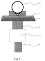
- the conductive core (12) can be connected to a conductive ball (17) like this is shown in Figure 3. This will have the effect to improve the form factor, so to reduce the fields avoiding the effects of peak, which will have as a direct consequence of increasing the tensile strength of the connector.
- the cable also has fastening means secondary mechanisms (11) intended to cooperate with the primary mechanical fastening means (7,8,9). They place at the junction of the soul with the part sheathed and connected to the shield of the cable.
- These means comprise in particular a portion (11) threaded allowing to fix the cable on the base during the cooperation of this party (11) with the means secondary (8) of the screw nut type cooperating with the downstream end (15) of the base (5).
- connection means located on the mechanical fastening means primaries may consist of a metal ring (6) in contact with the partition (2) and thus ensuring transmission of the contact to the shielding of the cable (13).
- the application of the device described above does not not limit the transition between a coaxial cable and a air line, but can also apply to other electrical components such as spark gaps, high voltage and low inductance splitters for coaxial cables, or at the cable connection high voltage.
- This partition crossing device can also be used to make a high probe voltage and high frequency and perform measurements referenced to a conductive ground plane. The measurement can be taken almost at the entrance of the cable and therefore directly below its characteristic impedance without inserting inductance corresponding to electrical lengths usually necessary to avoid breakdowns.
- a high voltage cable connection device using the same type of insulation means tablets for make the electrical sealing between the different components.
- This device includes two speakers insulators, one primary (19a) and the other secondary (19b).
- Each of these insulating enclosures (19a) and (19b) is respectively mounted on the primary conductive core (20a) of a first cable (27a) and the conductive core secondary (20b) of a second cable (27b).
- These cables first and second are of course those that require to be connected to each other using this device according to the invention.
- the two conductive cores (20a) and (20b) will therefore have to be electrically connected, this which will be realized by an element of electrical connection (21), in particular being of the ball type in which souls are likely to become infected.
- the insulated speakers can be designed in such a way that each can receive a half ball at its end.
- These primary (19a) and secondary (19b) insulating enclosures are respectively wrapped by means of recovery primary shielding (22a, 23a) and secondary shielding (22b, 23b); these primary shielding recovery means and these means secondary shielding rests are in contact and interdependent, each being electrically connected with the shielding (24a) or (24b) of the cable with which it cooperates.
- each of these means is broken down into two separate parts.
- a first part (22a) or (22b) can have a function similar to that described for the means primary mechanical fastening devices (7,8,9) of the crossing of partition shown in Figure 1.
- the second part (23a) or (23b) can then in the presented configuration be likened to the partition (2) of this same bushing partition.
- it is therefore a device for high voltage cable connection using for its realization two devices assembled with each other, these devices being substantially similar to those described as bulkhead traversing devices.
- Their assembly is done in this preferred embodiment by intermediary of the parts (23a) and (23b) of the means of recovery of primary and secondary shielding, assembly can be provided by threading these parts the making solidarity and in contact with each other.
- the device for high-voltage cable connection includes means of primary shielding (22a, 23a) and secondary shielding (22b, 23b) which must be electrically isolated from the souls primary (20a) and secondary (20b) conductors as well as of the electrical connection element (21).
- compressed electrical insulation means 25a, 25b, 26
- These isolation means electric tablets 25a, 25b, 26) are also located at two different places. First between each insulating enclosure (19a) or (19b) and the conductive core of the cable with which it cooperates.
- This part of the means electrical insulation tablets therefore takes, as in the partition penetration device, the shape of a plug cylindrical having the same properties as that described like the cylindrical plug (10) of the crossing of partition and being compressed in the same way.
- the second part of these electrical insulation means tablets is between the two ends opposite primary (19a) and secondary (19b) insulating enclosures.
- This part takes the form of a washer (26) placed around it of the electrical connection element (21), which is the occurrence in the embodiment describes a ball conductive.
- This washer (26) is also assimilable to the washer (4) of the bulkhead crossing device shown in Figure 1, showing the same characteristics than this last. Compression is here performed by clamping between the recovery means of primary shielding (22a, 23a) and the means for recovering shielding (22b, 23b).
- this tightening can be done by screwing parts (23a) and (23b) between them, the compression ratios being respected in relation to those that will be described for the washer (4) of the partition penetration device.
- These compressed electrical insulation means (25a, 25b, 26) will then prevent the formation of electric arcs between the different conductive elements of this device.
- the compression mechanism of the insulation means (4,10) in the bushing device Partition is as follows:
- the washer (4) is preferentially intended to be housed in the flange (16) of the base (5) and is compressed by clamping between the upstream end (14) emerging from the base (5) and the partition (2). This tightening is done by the displacement towards the partition of the rings (6,9) thus a pressure of the head of the end (14) against this partition (2).
- a sheet insulation (3) can be interposed between the partition and the upstream end (14).
- cylindrical plug (10) Other means of electrical insulation are constituted by the cylindrical plug (10). It is fit to be lodged in the central body (18), and is then compressed in two successive steps. In one first time, the cylindrical plug (10) undergoes a compression when positioned in the bore of the central body (18), due to the dimensions of its diameter outside which is slightly smaller than the diameter of the bore of the central body (18). In a second step, he is compressed by force-fitting the conductive core (12) of the cable in the clean bore of the plug, made by drilling before assembly. Indeed, this piercing will be done with a suitable drill bit so as to result in a diameter of the bore slightly smaller than the diameter of the conductive core (12) of the cable. This way of compressing insulation, being of course only one example among others, will then lead to the desired compression at from precise sizing parameters of the elements insulators used and that the skilled person will be able to determine.
- the core of the cable can cross the cap without degrading it, it is better to attach a rounded, smooth and conductive tip (no shown in the figure) welded to the end of the core.
- the reference material used here selected for its mechanical performance and insulation during testing, is a silicone sponge to closed cells, known as K495, marketed by Keeling Rubber & Plastics Ltd.
- the breakdown voltage also varies from linearly but according to the square root of the length of the insulation.
- This 60% barrier is the one identified for the product mostly tested, the K495, but can fluctuate of a few percent depending on whether we use other similar products made of silicone or other products. It is as well as thresholds of about 55% about 65%.
- the K495, very soft material, was placed in the collar (16) in the form of a washer (4). Insulation type Siloprene could not in this case replace the K495, to the extent that the compression needed to get electrical sealing could lead to the rupture of the device.
- the Silotationne has been arranged in the form of cylindrical plug in a bore of the central body (18), the K495 is too soft to penetrate the bore of the body having a diameter approximately two times smaller.
- the connector had exceeded the upstream end (14) beyond the partition (2) by a distance less than 7 mm for a voltage of fifty thousand volts, and less than 10 mm for a voltage of one hundred thousand volts.
- another preferred embodiment of the invention relates to a connection device of high voltage cables.
Landscapes
- Cable Accessories (AREA)
- Insulators (AREA)
- Installation Of Indoor Wiring (AREA)
Claims (18)
- Vorrichtung (1) zur Durchführung einer Trennwand (2), insbesondere einer Metalltrennwand für ein elektrisches Koaxial-Hochspannungskabel, mit einem an der Trennwand befestigten Isoliersockel (5), der einen Mittelkörper (18), ein vorgeordnetes Ende (14) und ein nachgeordnetes Ende (15) aufweist, wobei diese auf der einen bzw. auf der anderen Seite der Trennwand hervorstehen, wobei der Isoliersockel (5) dazu geeignet ist, von der leitenden Seele (12) eines Kabels (13) durchquert zu werden, sowie primäre Mittel (7, 8, 9) zur mechanischen Befestigung, die am nachgeordneten Ende des Sockels angeordnet sind und mit sekundären Mitteln (11) zur mechanischen Befestigung zusammenwirken sollen, die am ummantelten Abschnitt des Kabels (13) befestigt sind, dadurch gekennzeichnet, dass die leitende Seele (12) des Kabels (13) durch komprimierte Mittel (4, 10) zur elektrischen Isolierung elektrisch von der Trennwand (2) isoliert sind.
- Trennwanddurchführung nach Anspruch 1, dadurch gekennzeichnet, dass der Kompressionsgrad der Mittel (4, 10) zur elektrischen Isolierung mindestens 30% beträgt.
- Trennwanddurchführung nach Anspruch 1 oder 2, dadurch gekennzeichnet, dass die komprimierten Mittel (4, 10) zur elektrischen Isolierung zwischen dem vorgeordneten, aus dem Isoliersockel (5) ausgehenden Ende (14) und der Trennwand (2) sowie auf der Ebene des Mittelkörpers (18) zwischen der leitenden Seele (12) des Kabels und dem Isoliersockel (5) angeordnet sind.
- Trennwanddurchführung nach einem der vorhergehenden Ansprüche, dadurch gekennzeichnet, dass die Trennwand (2) auf der Seite des vorgeordneten Endes des Isoliersockels mit einer dünnen Isolierschicht (3) vom Typ Folie überzogen ist.
- Trennwanddurchführung nach einem der vorhergehenden Ansprüche, dadurch gekennzeichnet, dass das vorgeordnete, aus dem Isoliersockel ausgehende Ende (14) einen Kragen (16) aufweist, der dazu geeignet ist, einen Teil der Mittel (4, 10) zur elektrischen Isolierung zu enthalten.
- Trennwanddurchführung nach einem der vorhergehenden Ansprüche, dadurch gekennzeichnet, dass die primären Mittel zur mechanischen Befestigung ein Metallgehäuse (9) aufweisen, das dazu geeignet ist, mit Hilfe von primären Mitteln vom Typ Schraube-Mutter an dem nachgeordneten Ende (15) des Isoliersockels (5) befestigt zu werden und sekundäre Mittel (8) vom Typ Schraube-Mutter aufzunehmen, die mit den sekundären Befestigungsmitteln zusammenwirken sollen.
- Trennwanddurchführung nach einem der vorhergehenden Ansprüche, dadurch gekennzeichnet, dass die primären Mittel (7, 8, 9) zur mechanischen Befestigung elektrisch leitend sind und Mittel (6) für den elektrischen Anschluss aufweisen, die mit der Trennwand (2) zusammenwirken, und dass die sekundären Mittel (11) zur mechanischen Befestigung ebenfalls elektrisch leitend sind und elektrisch an die Kabelabschirmung angeschlossen sind.
- Trennwanddurchführung nach einem der vorhergehenden Ansprüche, dadurch gekennzeichnet, dass das vorgeordnete, aus dem Isoliersockel ausgehende Ende (14) dazu geeignet ist, mit elektrisch leitenden Mitteln vom Typ Kugel (17) zusammenzuwirken.
- Trennwanddurchführung nach einem der vorhergehenden Ansprüche, dadurch gekennzeichnet, dass die komprimierten Isoliermittel (4, 10) aus Materialien vom Typ Silikonschwamm realisiert sind.
- Trennwanddurchführung nach einem der vorhergehenden Ansprüche, dadurch gekennzeichnet, dass der Teil der Isoliermittel (4, 10), der sich zwischen der leitenden Seele (12) des Kabels (13) und dem Isoliersockel (5) befindet, ein zylindrischer Stopfen (10) ist, der mit einer Bohrung versehen ist, die aus der einen und der anderen Seite des Teils ausgeht, und dessen Kompression teilweise durch das Einsetzen mit Kraft der leitenden Seele (12) des Kabels in diese Bohrung realisiert ist.
- Trennwanddurchführung nach einem der vorhergehenden Ansprüche, dadurch gekennzeichnet, dass der Teil der Isoliermittel (4, 10), der sich zwischen dem vorgeordneten, aus dem Isoliersockel (5) ausgehenden Ende (14) und der Trennwand (2) befindet, eine kleine Scheibe (4) ist, deren Kompression durch das Klemmen der Vorrichtung (1) an der Wand (2) realisiert ist.
- Vorrichtung zur Verbindung von Hochspannungskabeln, mit einem primären Isolierraum (19a) und einem sekundären Isolierraum (19b), wobei der primäre Isolierraum (19a) und der sekundäre Isolierraum (19b) an einer primären, leitenden Seele (20a) eines ersten Kabels (27a) bzw. an einer sekundären, leitenden Seele (20b) eines zweiten Kabels (27b) angebracht sind, wobei diese beiden leitenden Seelen durch ein Element (21) für den elektrischen Anschluss verbunden werden sollen, wobei der primäre Isolierraum (19a) und der sekundäre Isolierraum (19b) dazu geeignet sind, mit primären Mitteln (22a, 23a) zur Abschirmungsverbindung bzw. sekundären Mitteln (22b, 23b) zur Abschirmungsverbindung umhüllt zu sein, wobei diese primären und sekundären Mittel zur Abschirmungsverbindung, die sich berühren, fest miteinander verbunden sind, dadurch gekennzeichnet, dass die primäre (20a) und sekundäre leitende Seele (20b) sowie das Element (21) für den elektrischen Anschluss mit Hilfe von komprimierten Mitteln (25a, 25b, 26) zur elektrischen Isolierung von den primären (22a, 23a) und sekundären Mitteln (22b, 23b) zur Abschirmungsverbindung elektrisch isoliert sind.
- Vorrichtung zur Verbindung von Hochspannungskabeln nach Anspruch 12, dadurch gekennzeichnet, dass der Kompressionsgrad der Mittel (25a, 25b, 26) zur elektrischen Isolierung mindestens 30% beträgt.
- Vorrichtung zur Verbindung von Hochspannungskabeln nach Anspruch 12 oder 13, dadurch gekennzeichnet, dass die komprimierten Mittel (25a, 25b, 26) zur elektrischen Isolierung zwischen dem primären Raum (19a) und dem sekundären Raum (19b) sowie zwischen jeder der leitenden Seelen (20a, 20b) und dem Isolierraum (19a, 19b), mit dem sie zusammenwirkt, angeordnet sind.
- Vorrichtung zur Verbindung von Kabeln nach einem der Ansprüche 12 bis 14, dadurch gekennzeichnet, dass das Element (21) für den elektrischen Anschluss vom Typ Kugel ist.
- Vorrichtung zur Verbindung von Kabeln nach einem der Ansprüche 12 bis 15, dadurch gekennzeichnet, dass die komprimierten Isoliermittel (25a, 25b, 26) aus Materialien vom Typ Silikonschwamm realisiert sind.
- Vorrichtung zur Verbindung von Kabeln nach einem der Ansprüche 12 bis 16, dadurch gekennzeichnet, dass der Teil der Isoliermittel (25a, 25b), der sich zwischen den leitenden Seelen (20a, 20b) und den Isolierräumen (19a, 19b), mit denen diese zusammenwirken, befindet, aus zylindrischen Stopfen (25a, 25b) besteht, die jeweils mit einer Bohrung versehen sind, welche aus der einen und der anderen Seite des Teils ausgehen, und deren Kompression teilweise durch das Einsetzen mit Kraft der primären (20a) und sekundären leitenden Seele (20b) realisiert ist.
- Vorrichtung zur Verbindung von Kabeln nach einem der Ansprüche 12 bis 17, dadurch gekennzeichnet, dass der Teil der Isoliermittel (26), der sich zwischen dem primären Isolierraum (19a) und dem sekundären Isolierraum (19b) befindet, eine runde Scheibe (26) ist, deren Kompression durch ein Klemmen der primären Mittel (22a, 23a) zur Abschirmungsverbindung mit den sekundären Mitteln (22b, 23b) zur Abschirmungsverbindung realisiert ist.
Applications Claiming Priority (2)
| Application Number | Priority Date | Filing Date | Title |
|---|---|---|---|
| FR0014594A FR2816771B1 (fr) | 2000-11-14 | 2000-11-14 | Dispositif de traversee de cloison |
| FR0014594 | 2000-11-14 |
Publications (2)
| Publication Number | Publication Date |
|---|---|
| EP1205947A1 EP1205947A1 (de) | 2002-05-15 |
| EP1205947B1 true EP1205947B1 (de) | 2005-08-31 |
Family
ID=8856396
Family Applications (1)
| Application Number | Title | Priority Date | Filing Date |
|---|---|---|---|
| EP01402919A Expired - Lifetime EP1205947B1 (de) | 2000-11-14 | 2001-11-14 | Trennwanddurchführung für elektrisches Hochspannungskabel |
Country Status (4)
| Country | Link |
|---|---|
| US (2) | US6617512B2 (de) |
| EP (1) | EP1205947B1 (de) |
| DE (1) | DE60113037T2 (de) |
| FR (1) | FR2816771B1 (de) |
Families Citing this family (5)
| Publication number | Priority date | Publication date | Assignee | Title |
|---|---|---|---|---|
| US7014502B2 (en) * | 2003-04-04 | 2006-03-21 | Anlynk Wireless, Llc | RF feedthrough coaxial connector for wireless communications in hazardous environments |
| US7355130B2 (en) * | 2004-04-09 | 2008-04-08 | Siemens Information And Communication Networks, Inc. | Cable sealing device |
| FR2923954B1 (fr) * | 2007-11-20 | 2010-02-26 | Schneider Electric Ind Sas | Connexion blindee de deux bornes par contact entre interfaces planes. |
| CN102651509B (zh) * | 2011-02-25 | 2014-03-12 | 富士康(昆山)电脑接插件有限公司 | 电连接器 |
| IL295162B2 (en) * | 2022-07-28 | 2024-10-01 | Applied Materials Israel Ltd | High-voltage feedthrough kit |
Family Cites Families (5)
| Publication number | Priority date | Publication date | Assignee | Title |
|---|---|---|---|---|
| US3662082A (en) * | 1970-09-03 | 1972-05-09 | G & W Electric Speciality Co | High voltage cable terminating assembly |
| US4508797A (en) * | 1983-07-26 | 1985-04-02 | The United States Of America As Represented By The United States Department Of Energy | Hermetically sealed electrical feedthrough for high temperature secondary cells |
| DE3843943A1 (de) * | 1988-12-24 | 1990-06-28 | Asea Brown Boveri | Stromrichtergehaeuse und verfahren zur herstellung von durchfuehrungsanordnungen an diesem gehaeuse |
| US5644104A (en) * | 1994-12-19 | 1997-07-01 | Porter; Fred C. | Assembly for permitting the transmission of an electrical signal between areas of different pressure |
| US6632100B1 (en) * | 1997-04-23 | 2003-10-14 | Anthony, Inc. | Lighting system method and apparatus socket assembly lamp insulator assembly and components thereof |
-
2000
- 2000-11-14 FR FR0014594A patent/FR2816771B1/fr not_active Expired - Lifetime
-
2001
- 2001-11-14 US US09/987,429 patent/US6617512B2/en not_active Expired - Lifetime
- 2001-11-14 DE DE60113037T patent/DE60113037T2/de not_active Expired - Lifetime
- 2001-11-14 EP EP01402919A patent/EP1205947B1/de not_active Expired - Lifetime
-
2003
- 2003-05-07 US US10/430,258 patent/US6857901B2/en not_active Expired - Fee Related
Also Published As
| Publication number | Publication date |
|---|---|
| US6857901B2 (en) | 2005-02-22 |
| DE60113037D1 (de) | 2005-10-06 |
| DE60113037T2 (de) | 2006-06-29 |
| FR2816771A1 (fr) | 2002-05-17 |
| US20040009701A1 (en) | 2004-01-15 |
| FR2816771B1 (fr) | 2004-11-19 |
| US6617512B2 (en) | 2003-09-09 |
| EP1205947A1 (de) | 2002-05-15 |
| US20020112872A1 (en) | 2002-08-22 |
Similar Documents
| Publication | Publication Date | Title |
|---|---|---|
| EP0086136A1 (de) | Generator elektromagnetischer Hochspannungsimpulse | |
| WO2008104668A1 (fr) | Procede de fabrication d'un cable de raccordement de poles de batterie, l'installation de mise en oeuvre et le cable obtenu | |
| FR2953322A1 (fr) | Interrupteur electrique formant coupe-circuit a actionnement rapide | |
| CA2722398A1 (fr) | Chemin de cable evolutif pour aeronef a structure en materiau composite | |
| FR2925214A1 (fr) | Court-circuit pyrotechnique a contacts electrique auto-serrant et ensemble de protection contre les arcs internes comportant un tel court-circuiteur | |
| EP1205947B1 (de) | Trennwanddurchführung für elektrisches Hochspannungskabel | |
| EP3644468B1 (de) | Kabelverbindungsvorrichtung mit integriertem raumladungsdetektor | |
| EP0596775A1 (de) | Blitzableiter mit Entzündungsvorrichtung mit gleitender elektrischer Entladung längs eines dielektrischen Teiles | |
| EP0645782B1 (de) | Mehrzweckstromdurchführung | |
| EP3772140A1 (de) | Elektrischer anschluss und elektrische verbindungsvorrichtung | |
| EP1394900A1 (de) | Verbinder für zwei elecktrische Energiekabel und Verbindung mit einem solchen Verbinder | |
| EP1629577B1 (de) | Funkenstrecke, insbesondere hochspannungsfunkenstrecke | |
| EP0236642B1 (de) | Hochspannungstransformator | |
| CH621653A5 (de) | ||
| FR3028677A1 (fr) | Assemblage d'un ensemble de raccordement electrique | |
| EP1300913B1 (de) | Im Vakuum operierender Hochspannungsstromverbinder | |
| FR2664751A1 (fr) | Systeme de mise en contact des conducteurs interieurs d'un cable coaxial et d'une fiche coaxiale, et dispositif pour le montage de ce systeme. | |
| EP0142200B1 (de) | Anordnung zur Elektrodenspannungsregelung für Kathodenstrahlröhren | |
| FR2716721A1 (fr) | Procédé et dispositif de contrôle de l'intégrité de moyens d'isolation électrique d'un objet comportant des moyens conducteurs. | |
| FR2958807A1 (fr) | Dispositif de connexion de deux cables supraconducteurs | |
| EP2458687A1 (de) | Elektrische Verbindungsanordnung aus einem Hochspannungskabel, und Verbindungsvorrichtung | |
| WO2018001891A1 (fr) | Connecteur de raccordement | |
| FR2923954A1 (fr) | Connexion blindee de deux bornes par contact entre interfaces planes. | |
| EP0219494B1 (de) | Blitzschutzschaltung für empfindliche elektrische anlagen und solche vorrichtungen | |
| FR2719420A1 (fr) | Procédé et dispositif d'accouplement de composants électriques haute tension. |
Legal Events
| Date | Code | Title | Description |
|---|---|---|---|
| PUAI | Public reference made under article 153(3) epc to a published international application that has entered the european phase |
Free format text: ORIGINAL CODE: 0009012 |
|
| 17P | Request for examination filed |
Effective date: 20011130 |
|
| AK | Designated contracting states |
Kind code of ref document: A1 Designated state(s): AT BE CH CY DE DK ES FI FR GB GR IE IT LI LU MC NL PT SE TR |
|
| AX | Request for extension of the european patent |
Free format text: AL;LT;LV;MK;RO;SI |
|
| AKX | Designation fees paid |
Designated state(s): CH DE GB LI |
|
| GRAP | Despatch of communication of intention to grant a patent |
Free format text: ORIGINAL CODE: EPIDOSNIGR1 |
|
| GRAS | Grant fee paid |
Free format text: ORIGINAL CODE: EPIDOSNIGR3 |
|
| GRAA | (expected) grant |
Free format text: ORIGINAL CODE: 0009210 |
|
| AK | Designated contracting states |
Kind code of ref document: B1 Designated state(s): CH DE GB LI |
|
| REG | Reference to a national code |
Ref country code: CH Ref legal event code: EP Ref country code: GB Ref legal event code: FG4D Free format text: NOT ENGLISH |
|
| REF | Corresponds to: |
Ref document number: 60113037 Country of ref document: DE Date of ref document: 20051006 Kind code of ref document: P |
|
| REG | Reference to a national code |
Ref country code: CH Ref legal event code: NV Representative=s name: BUGNION S.A. |
|
| GBT | Gb: translation of ep patent filed (gb section 77(6)(a)/1977) |
Effective date: 20051201 |
|
| PLBE | No opposition filed within time limit |
Free format text: ORIGINAL CODE: 0009261 |
|
| STAA | Information on the status of an ep patent application or granted ep patent |
Free format text: STATUS: NO OPPOSITION FILED WITHIN TIME LIMIT |
|
| 26N | No opposition filed |
Effective date: 20060601 |
|
| REG | Reference to a national code |
Ref country code: GB Ref legal event code: 732E Free format text: REGISTERED BETWEEN 20101209 AND 20101215 |
|
| PGFP | Annual fee paid to national office [announced via postgrant information from national office to epo] |
Ref country code: CH Payment date: 20180529 Year of fee payment: 17 Ref country code: DE Payment date: 20180530 Year of fee payment: 17 |
|
| PGFP | Annual fee paid to national office [announced via postgrant information from national office to epo] |
Ref country code: GB Payment date: 20180529 Year of fee payment: 17 |
|
| REG | Reference to a national code |
Ref country code: DE Ref legal event code: R119 Ref document number: 60113037 Country of ref document: DE |
|
| REG | Reference to a national code |
Ref country code: CH Ref legal event code: PL |
|
| GBPC | Gb: european patent ceased through non-payment of renewal fee |
Effective date: 20181114 |
|
| PG25 | Lapsed in a contracting state [announced via postgrant information from national office to epo] |
Ref country code: LI Free format text: LAPSE BECAUSE OF NON-PAYMENT OF DUE FEES Effective date: 20181130 Ref country code: CH Free format text: LAPSE BECAUSE OF NON-PAYMENT OF DUE FEES Effective date: 20181130 |
|
| PG25 | Lapsed in a contracting state [announced via postgrant information from national office to epo] |
Ref country code: DE Free format text: LAPSE BECAUSE OF NON-PAYMENT OF DUE FEES Effective date: 20190601 |
|
| PG25 | Lapsed in a contracting state [announced via postgrant information from national office to epo] |
Ref country code: GB Free format text: LAPSE BECAUSE OF NON-PAYMENT OF DUE FEES Effective date: 20181114 |