EP1205953A2 - Dispositif de télécommande pour un récepteur - Google Patents
Dispositif de télécommande pour un récepteur Download PDFInfo
- Publication number
- EP1205953A2 EP1205953A2 EP01830464A EP01830464A EP1205953A2 EP 1205953 A2 EP1205953 A2 EP 1205953A2 EP 01830464 A EP01830464 A EP 01830464A EP 01830464 A EP01830464 A EP 01830464A EP 1205953 A2 EP1205953 A2 EP 1205953A2
- Authority
- EP
- European Patent Office
- Prior art keywords
- cover element
- case body
- mouldings
- foregoing
- longitudinal axis
- Prior art date
- Legal status (The legal status is an assumption and is not a legal conclusion. Google has not performed a legal analysis and makes no representation as to the accuracy of the status listed.)
- Granted
Links
Images


Classifications
-
- H—ELECTRICITY
- H01—ELECTRIC ELEMENTS
- H01H—ELECTRIC SWITCHES; RELAYS; SELECTORS; EMERGENCY PROTECTIVE DEVICES
- H01H9/00—Details of switching devices, not covered by groups H01H1/00 - H01H7/00
- H01H9/02—Bases, casings, or covers
- H01H9/0214—Hand-held casings
- H01H9/0235—Hand-held casings specially adapted for remote control, e.g. of audio or video apparatus
- H01H9/0242—Protective enclosures; Cushioning means
Definitions
- the present invention relates to a remote control device for a receiver.
- box-shaped bodies normally consist of a box-shaped body containing all of the circuitry required to generate the signals to be sent to a receiver which converts the signals into commands.
- the box-shaped body has a plurality of keys which are connected to the internal circuit. Therefore, by pressing different keys (even in particular sequences), the operator can obtain the desired function from the receiver.
- remote controls are designed to be easily transported and handled by the user and, therefore, are small.
- known remote controls are made in such a way that they can be held and operated with just one hand.
- the prior art teaches the use of cases made of a deformable material (normally an elastomeric material) in which the remote control can be inserted, so as to lessen the impact suffered and, as a result, limit any damage.
- a deformable material normally an elastomeric material
- a first practical disadvantage of this type of protective device is the difficulty in adapting it to fit remote controls of different sizes.
- protective cases do not have a sufficiently low coefficient of elasticity to provide satisfactory adaptation characteristics, since their shape and dimensions are substantially ready-formed and, as a result, they can only be used on a limited number of remote controls.
- the aim of the present invention is to provide a remote control device, in particular for domestic appliances, which is effectively protected from external bumps and impact.
- Another aim of the present invention is to provide a remote control device, in particular for domestic appliances, which is practical and easy to handle.
- Another aim of the present invention is to provide a remote control device, in particular for domestic appliances, with dimensions which are substantially identical to those of a conventional remote control.
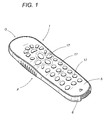
- the remote control device according to the present invention is labelled 1 as a whole in the accompanying drawings.
- the device 1 comprises a case body 2, which is substantially box-shaped (illustrated in Figure 2), on which a closing plate 5 is securely fixed.
- the case body 2 has an internal surface 3 which forms a housing 8. Inside said housing 8 there are electronic control means 7, whose function is to generate electromagnetic control signals with which the user can operate a receiver.
- a cover element 6 fixed to an outer surface 4 of the case body 2 in such a way that it cannot be removed.
- the cover element 6 is a sheath made of an elastomeric material which surrounds the case body 2.
- a power unit 10 (basically, the batteries) is inserted, to allow operation of the electronic control means 7.
- the cover element 6 has a through-hole 11, allowing the user access to the power unit 10 so that, for example, it may be substituted when low.
- the device 1 has a sealing cover 12 which normally seals the above-mentioned through-hole 11, and which is fixed close to the hole 11.
- the sealing cover 12 may be removed, allowing access to the power unit 10 if necessary.
- the sealing cover 12 is made in such a way that its shape substantially matches that of the through-hole 11 in the cover element 6.
- the sealing cover 12 (as is schematically illustrated in Figure 2) normally consists of a single rigid surface 13.
- this sealing cover may comprise a first layer 13 made of a rigid material, and a second layer 14 (illustrated with a dashed line), fixed to the first layer 13 and made of an elastomeric material.
- the first layer 13 is opposite the power unit 10 whilst the second layer 14 may be an extension of the cover element 6, forming a single, substantially continuous surface with the above-mentioned cover element 6.
- the cavity 9 is made in the outer surface 4 in such a way that the power unit 10 is distanced from the surface on which the device 1 rests. This feature allows improved isolation of the power unit 10 from humidity and, in general, from harmful substances with which the cover element 6 may come into contact.
- the case body 2 and cover element 6 have an elongated shape and extend substantially in a direction defined by a longitudinal axis (not illustrated) of the case body 2. Moreover, to improve both the user's grip and the natural barycentre, the cover element 6 has a curved configuration 6a on the side opposite the case body 2 (see Figure 4).
- a suitable distribution of the weights of the various parts of the device 1 means that, when the device 1 is placed on a surface in such a way that it rests on the cover element 6, it maintains a substantially stable, balanced position.
- the cover element 6 also has a plurality of mouldings 15 (see Figure 3) which extend transversally relative to the longitudinal axis of the case body 2, and of which at least three, labelled 15a, 15b and 15c, are contact zones for resting the device 1 on a fixed surface PF.
- two of these mouldings, 15a and 15b, are located at the ends of the cover element 6, whilst the third is substantially at the centre of the cover element 6.
- the sealing cover 12 of the through-hole 11 in the cover element 6 has a convex shape such that the through-hole remains clear of the fixed surface PF. This protects the electrical contacts from any liquids or other elements present on the fixed surface PF, which might damage the circuits in the device 1.
- the control means 7 basically consist of an electronic circuit 16 and a plurality of elements 17 for operation of the electronic circuit 16.
- the electronic circuit 16 is positioned inside the housing 8, formed by the inner surface 3 of the case body 2 and is designed to generate electromagnetic signals to be sent to the receiver (for example, a television).
- the operating elements 17 are normally keys positioned in a plurality of through-holes 18 made in the closing plate 5. In this way, the keys may be reached by the user who, pressing them, can select which control signals should be transmitted to the receiver.
- the cover element 6 has at least one extending portion 19, extending transversally to the longitudinal axis of the case body 2, that is to say, parallel with the mouldings 15.
- the function of said portion 19, which partially covers the closing plate 5, is to prevent any damage to the device 1 if the device 1 is dropped or bumped on the closing plate 5.
- the present invention has important advantages.
- a remote control device for a receiver which is made in accordance with the present invention is extremely practical and easy to handle, since the addition of the protective material does not change its dimensions relative to those of a conventional remote control and does not obstruct user access to the keypad.
- Another advantage lies in the fact that, thanks to suitable shaping of the profile of the transversal mouldings in the deformable material, it is easier for the user to grip and much more secure than a conventional remote control, with reduced risks even for the internal circuits. The risk of dropping the remote control, with consequent malfunctions, is therefore much reduced.
- the remote control device according to the present invention is extremely advantageous since, with a protective structure like the one described above, the product obtained is substantially the same price as a conventional remote control, but has the added advantage of being shock resistant to bumps and less easy to drop.
- a further advantage emerges by observing that a careful distribution of the weights and shape of the various parts of the device allows the device to remain in a stable, balanced position when placed with the keys uppermost, despite the fact that the deformable portion has a curved configuration in the area rested on the surface.
Landscapes
- Engineering & Computer Science (AREA)
- Multimedia (AREA)
- Selective Calling Equipment (AREA)
- Input Circuits Of Receivers And Coupling Of Receivers And Audio Equipment (AREA)
- Details Of Television Systems (AREA)
Applications Claiming Priority (2)
| Application Number | Priority Date | Filing Date | Title |
|---|---|---|---|
| IT2000BO000649A ITBO20000649A1 (it) | 2000-11-09 | 2000-11-09 | Dispositivo per il controllo a distanza di un apparecchio ricevitore |
| ITBO000649 | 2000-11-09 |
Publications (3)
| Publication Number | Publication Date |
|---|---|
| EP1205953A2 true EP1205953A2 (fr) | 2002-05-15 |
| EP1205953A3 EP1205953A3 (fr) | 2002-12-11 |
| EP1205953B1 EP1205953B1 (fr) | 2004-10-13 |
Family
ID=11438839
Family Applications (1)
| Application Number | Title | Priority Date | Filing Date |
|---|---|---|---|
| EP01830464A Expired - Lifetime EP1205953B1 (fr) | 2000-11-09 | 2001-07-12 | Dispositif de télécommande pour un récepteur |
Country Status (5)
| Country | Link |
|---|---|
| EP (1) | EP1205953B1 (fr) |
| AT (1) | ATE279780T1 (fr) |
| DE (1) | DE60106369T2 (fr) |
| ES (1) | ES2228786T3 (fr) |
| IT (1) | ITBO20000649A1 (fr) |
Cited By (1)
| Publication number | Priority date | Publication date | Assignee | Title |
|---|---|---|---|---|
| EP1515380A1 (fr) * | 2003-09-12 | 2005-03-16 | Brother Kogyo Kabushiki Kaisha | Appareil électronique avec structure absorbant de chocs |
Family Cites Families (4)
| Publication number | Priority date | Publication date | Assignee | Title |
|---|---|---|---|---|
| IT1208461B (it) * | 1987-01-30 | 1989-06-22 | Granarolo Dell Emilia Bo Melic | Custodia protettiva antiurto per telecomandi in particolare di televisori |
| IT224920Z2 (it) * | 1990-10-16 | 1996-07-30 | Meliconi Spa | Custodia protettiva antiurto in particolare per prodotti quali teleco-mandi per televisori, registratori, e apparecchi comandabili a distan-za in genere o anche strumenti ad uso personale o professionale. |
| US5422783A (en) * | 1992-07-06 | 1995-06-06 | Universal Electronics Inc. | Modular casing for a remote control having upper housing member slidingly received in a panel section |
| US5383091A (en) * | 1993-02-22 | 1995-01-17 | Sony Electronics, Inc. | Grip and protective casing for cellular telephone |
-
2000
- 2000-11-09 IT IT2000BO000649A patent/ITBO20000649A1/it unknown
-
2001
- 2001-07-12 EP EP01830464A patent/EP1205953B1/fr not_active Expired - Lifetime
- 2001-07-12 DE DE60106369T patent/DE60106369T2/de not_active Expired - Lifetime
- 2001-07-12 ES ES01830464T patent/ES2228786T3/es not_active Expired - Lifetime
- 2001-07-12 AT AT01830464T patent/ATE279780T1/de not_active IP Right Cessation
Cited By (3)
| Publication number | Priority date | Publication date | Assignee | Title |
|---|---|---|---|---|
| EP1515380A1 (fr) * | 2003-09-12 | 2005-03-16 | Brother Kogyo Kabushiki Kaisha | Appareil électronique avec structure absorbant de chocs |
| US7067735B2 (en) | 2003-09-12 | 2006-06-27 | Brother Kogyo Kabushiki Kaisha | Electronic device with impact absorbing structure |
| CN100343066C (zh) * | 2003-09-12 | 2007-10-17 | 兄弟工业株式会社 | 具有冲击吸收结构的电子装置 |
Also Published As
| Publication number | Publication date |
|---|---|
| DE60106369D1 (de) | 2004-11-18 |
| ES2228786T3 (es) | 2005-04-16 |
| EP1205953A3 (fr) | 2002-12-11 |
| ATE279780T1 (de) | 2004-10-15 |
| ITBO20000649A0 (it) | 2000-11-09 |
| DE60106369T2 (de) | 2005-11-17 |
| ITBO20000649A1 (it) | 2002-05-09 |
| EP1205953B1 (fr) | 2004-10-13 |
Similar Documents
| Publication | Publication Date | Title |
|---|---|---|
| USD449279S1 (en) | Electrical equipment housing cover | |
| USD487733S1 (en) | Housing for communications devices or similar articles | |
| USD470842S1 (en) | Portable handheld terminal housing | |
| US5865098A (en) | Multiple container slow cooker device | |
| USD473550S1 (en) | Housing for a communication device or similar articles | |
| US4257121A (en) | Portable transceiver | |
| CA2109841A1 (fr) | Boitier de protection pour commandes a distance | |
| US4439654A (en) | Waterproof control knob assembly with integral switch | |
| USD508236S1 (en) | Protective casing for electrical or electronic apparatus | |
| WO2002014160A3 (fr) | Caisse d'emballage | |
| CA2404307A1 (fr) | Grille-pain | |
| WO2003047914A1 (fr) | Bouton de poignee de commande d'un gerbeur | |
| EP0504359B1 (fr) | Enveloppe de protection en particulier pour des telecommandes de televiseurs de magnetoscopes et d'autres instruments d'usage personnel et professionnel | |
| EP1205953B1 (fr) | Dispositif de télécommande pour un récepteur | |
| EP1966541B1 (fr) | Cuiseur | |
| GB2259172B (en) | Wireless remote control transmitter and receiver for electrical appliances | |
| WO2002075333A3 (fr) | Programmateur portable intrinsequement sur pour equipement electronique de commande de processus encastre | |
| USD453921S1 (en) | Instrument connector | |
| JP4694531B2 (ja) | 電気器具のスイッチ装置 | |
| AU6543296A (en) | Wireless remote control transmitter for use with consumer entertainment electronics appliance | |
| GB2366367B (en) | Electrical oven having a housing with a pivotally mounted lid | |
| EP0766275B1 (fr) | Clavier | |
| USD447906S1 (en) | Sliding lid and pan | |
| USD432502S (en) | Housing for a cable television tap | |
| USD446078S1 (en) | Knob for a cookware lid |
Legal Events
| Date | Code | Title | Description |
|---|---|---|---|
| PUAI | Public reference made under article 153(3) epc to a published international application that has entered the european phase |
Free format text: ORIGINAL CODE: 0009012 |
|
| AK | Designated contracting states |
Kind code of ref document: A2 Designated state(s): AT BE CH CY DE DK ES FI FR GB GR IE IT LI LU MC NL PT SE TR |
|
| AX | Request for extension of the european patent |
Free format text: AL;LT;LV;MK;RO;SI |
|
| PUAL | Search report despatched |
Free format text: ORIGINAL CODE: 0009013 |
|
| AK | Designated contracting states |
Kind code of ref document: A3 Designated state(s): AT BE CH CY DE DK ES FI FR GB GR IE IT LI LU MC NL PT SE TR |
|
| AX | Request for extension of the european patent |
Free format text: AL;LT;LV;MK;RO;SI |
|
| 17P | Request for examination filed |
Effective date: 20030210 |
|
| AKX | Designation fees paid |
Designated state(s): AT BE CH CY DE DK ES FI FR GB GR IE IT LI LU MC NL PT SE TR |
|
| 17Q | First examination report despatched |
Effective date: 20030730 |
|
| GRAP | Despatch of communication of intention to grant a patent |
Free format text: ORIGINAL CODE: EPIDOSNIGR1 |
|
| GRAS | Grant fee paid |
Free format text: ORIGINAL CODE: EPIDOSNIGR3 |
|
| GRAA | (expected) grant |
Free format text: ORIGINAL CODE: 0009210 |
|
| AK | Designated contracting states |
Kind code of ref document: B1 Designated state(s): AT BE CH CY DE DK ES FI FR GB GR IE IT LI LU MC NL PT SE TR |
|
| PG25 | Lapsed in a contracting state [announced via postgrant information from national office to epo] |
Ref country code: AT Free format text: LAPSE BECAUSE OF FAILURE TO SUBMIT A TRANSLATION OF THE DESCRIPTION OR TO PAY THE FEE WITHIN THE PRESCRIBED TIME-LIMIT Effective date: 20041013 Ref country code: CH Free format text: LAPSE BECAUSE OF FAILURE TO SUBMIT A TRANSLATION OF THE DESCRIPTION OR TO PAY THE FEE WITHIN THE PRESCRIBED TIME-LIMIT Effective date: 20041013 Ref country code: LI Free format text: LAPSE BECAUSE OF FAILURE TO SUBMIT A TRANSLATION OF THE DESCRIPTION OR TO PAY THE FEE WITHIN THE PRESCRIBED TIME-LIMIT Effective date: 20041013 Ref country code: TR Free format text: LAPSE BECAUSE OF FAILURE TO SUBMIT A TRANSLATION OF THE DESCRIPTION OR TO PAY THE FEE WITHIN THE PRESCRIBED TIME-LIMIT Effective date: 20041013 Ref country code: BE Free format text: LAPSE BECAUSE OF FAILURE TO SUBMIT A TRANSLATION OF THE DESCRIPTION OR TO PAY THE FEE WITHIN THE PRESCRIBED TIME-LIMIT Effective date: 20041013 Ref country code: FI Free format text: LAPSE BECAUSE OF FAILURE TO SUBMIT A TRANSLATION OF THE DESCRIPTION OR TO PAY THE FEE WITHIN THE PRESCRIBED TIME-LIMIT Effective date: 20041013 |
|
| REG | Reference to a national code |
Ref country code: GB Ref legal event code: FG4D |
|
| REG | Reference to a national code |
Ref country code: CH Ref legal event code: EP |
|
| REG | Reference to a national code |
Ref country code: IE Ref legal event code: FG4D |
|
| REF | Corresponds to: |
Ref document number: 60106369 Country of ref document: DE Date of ref document: 20041118 Kind code of ref document: P |
|
| PG25 | Lapsed in a contracting state [announced via postgrant information from national office to epo] |
Ref country code: DK Free format text: LAPSE BECAUSE OF FAILURE TO SUBMIT A TRANSLATION OF THE DESCRIPTION OR TO PAY THE FEE WITHIN THE PRESCRIBED TIME-LIMIT Effective date: 20050113 Ref country code: SE Free format text: LAPSE BECAUSE OF FAILURE TO SUBMIT A TRANSLATION OF THE DESCRIPTION OR TO PAY THE FEE WITHIN THE PRESCRIBED TIME-LIMIT Effective date: 20050113 Ref country code: GR Free format text: LAPSE BECAUSE OF FAILURE TO SUBMIT A TRANSLATION OF THE DESCRIPTION OR TO PAY THE FEE WITHIN THE PRESCRIBED TIME-LIMIT Effective date: 20050113 |
|
| REG | Reference to a national code |
Ref country code: ES Ref legal event code: FG2A Ref document number: 2228786 Country of ref document: ES Kind code of ref document: T3 |
|
| REG | Reference to a national code |
Ref country code: CH Ref legal event code: PL |
|
| PG25 | Lapsed in a contracting state [announced via postgrant information from national office to epo] |
Ref country code: CY Free format text: LAPSE BECAUSE OF FAILURE TO SUBMIT A TRANSLATION OF THE DESCRIPTION OR TO PAY THE FEE WITHIN THE PRESCRIBED TIME-LIMIT Effective date: 20050712 Ref country code: IE Free format text: LAPSE BECAUSE OF NON-PAYMENT OF DUE FEES Effective date: 20050712 Ref country code: LU Free format text: LAPSE BECAUSE OF NON-PAYMENT OF DUE FEES Effective date: 20050712 |
|
| PG25 | Lapsed in a contracting state [announced via postgrant information from national office to epo] |
Ref country code: MC Free format text: LAPSE BECAUSE OF NON-PAYMENT OF DUE FEES Effective date: 20050731 |
|
| PLBE | No opposition filed within time limit |
Free format text: ORIGINAL CODE: 0009261 |
|
| STAA | Information on the status of an ep patent application or granted ep patent |
Free format text: STATUS: NO OPPOSITION FILED WITHIN TIME LIMIT |
|
| ET | Fr: translation filed | ||
| 26N | No opposition filed |
Effective date: 20050714 |
|
| REG | Reference to a national code |
Ref country code: IE Ref legal event code: MM4A |
|
| PG25 | Lapsed in a contracting state [announced via postgrant information from national office to epo] |
Ref country code: PT Free format text: LAPSE BECAUSE OF NON-PAYMENT OF DUE FEES Effective date: 20050313 |
|
| REG | Reference to a national code |
Ref country code: FR Ref legal event code: PLFP Year of fee payment: 16 |
|
| REG | Reference to a national code |
Ref country code: FR Ref legal event code: PLFP Year of fee payment: 17 |
|
| PGFP | Annual fee paid to national office [announced via postgrant information from national office to epo] |
Ref country code: NL Payment date: 20170725 Year of fee payment: 17 |
|
| PGFP | Annual fee paid to national office [announced via postgrant information from national office to epo] |
Ref country code: ES Payment date: 20170830 Year of fee payment: 17 Ref country code: GB Payment date: 20170728 Year of fee payment: 17 |
|
| PGFP | Annual fee paid to national office [announced via postgrant information from national office to epo] |
Ref country code: DE Payment date: 20170929 Year of fee payment: 17 |
|
| REG | Reference to a national code |
Ref country code: FR Ref legal event code: PLFP Year of fee payment: 18 |
|
| REG | Reference to a national code |
Ref country code: DE Ref legal event code: R119 Ref document number: 60106369 Country of ref document: DE |
|
| REG | Reference to a national code |
Ref country code: NL Ref legal event code: MM Effective date: 20180801 |
|
| GBPC | Gb: european patent ceased through non-payment of renewal fee |
Effective date: 20180712 |
|
| PG25 | Lapsed in a contracting state [announced via postgrant information from national office to epo] |
Ref country code: GB Free format text: LAPSE BECAUSE OF NON-PAYMENT OF DUE FEES Effective date: 20180712 Ref country code: DE Free format text: LAPSE BECAUSE OF NON-PAYMENT OF DUE FEES Effective date: 20190201 |
|
| PG25 | Lapsed in a contracting state [announced via postgrant information from national office to epo] |
Ref country code: NL Free format text: LAPSE BECAUSE OF NON-PAYMENT OF DUE FEES Effective date: 20180801 |
|
| REG | Reference to a national code |
Ref country code: ES Ref legal event code: FD2A Effective date: 20190917 |
|
| PG25 | Lapsed in a contracting state [announced via postgrant information from national office to epo] |
Ref country code: ES Free format text: LAPSE BECAUSE OF NON-PAYMENT OF DUE FEES Effective date: 20180713 |
|
| PGFP | Annual fee paid to national office [announced via postgrant information from national office to epo] |
Ref country code: FR Payment date: 20200728 Year of fee payment: 20 |
|
| PGFP | Annual fee paid to national office [announced via postgrant information from national office to epo] |
Ref country code: IT Payment date: 20200715 Year of fee payment: 20 |