EP1206015A2 - Connecteur avec bruit diaphonique réduit - Google Patents
Connecteur avec bruit diaphonique réduit Download PDFInfo
- Publication number
- EP1206015A2 EP1206015A2 EP01309508A EP01309508A EP1206015A2 EP 1206015 A2 EP1206015 A2 EP 1206015A2 EP 01309508 A EP01309508 A EP 01309508A EP 01309508 A EP01309508 A EP 01309508A EP 1206015 A2 EP1206015 A2 EP 1206015A2
- Authority
- EP
- European Patent Office
- Prior art keywords
- connector
- cable
- insert
- contacts
- array
- Prior art date
- Legal status (The legal status is an assumption and is not a legal conclusion. Google has not performed a legal analysis and makes no representation as to the accuracy of the status listed.)
- Granted
Links
Images







Classifications
-
- H—ELECTRICITY
- H01—ELECTRIC ELEMENTS
- H01R—ELECTRICALLY-CONDUCTIVE CONNECTIONS; STRUCTURAL ASSOCIATIONS OF A PLURALITY OF MUTUALLY-INSULATED ELECTRICAL CONNECTING ELEMENTS; COUPLING DEVICES; CURRENT COLLECTORS
- H01R13/00—Details of coupling devices of the kinds covered by groups H01R12/70 or H01R24/00 - H01R33/00
- H01R13/646—Details of coupling devices of the kinds covered by groups H01R12/70 or H01R24/00 - H01R33/00 specially adapted for high-frequency, e.g. structures providing an impedance match or phase match
- H01R13/6461—Means for preventing cross-talk
- H01R13/6463—Means for preventing cross-talk using twisted pairs of wires
-
- H—ELECTRICITY
- H01—ELECTRIC ELEMENTS
- H01R—ELECTRICALLY-CONDUCTIVE CONNECTIONS; STRUCTURAL ASSOCIATIONS OF A PLURALITY OF MUTUALLY-INSULATED ELECTRICAL CONNECTING ELEMENTS; COUPLING DEVICES; CURRENT COLLECTORS
- H01R24/00—Two-part coupling devices, or either of their cooperating parts, characterised by their overall structure
- H01R24/60—Contacts spaced along planar side wall transverse to longitudinal axis of engagement
- H01R24/62—Sliding engagements with one side only, e.g. modular jack coupling devices
-
- Y—GENERAL TAGGING OF NEW TECHNOLOGICAL DEVELOPMENTS; GENERAL TAGGING OF CROSS-SECTIONAL TECHNOLOGIES SPANNING OVER SEVERAL SECTIONS OF THE IPC; TECHNICAL SUBJECTS COVERED BY FORMER USPC CROSS-REFERENCE ART COLLECTIONS [XRACs] AND DIGESTS
- Y10—TECHNICAL SUBJECTS COVERED BY FORMER USPC
- Y10S—TECHNICAL SUBJECTS COVERED BY FORMER USPC CROSS-REFERENCE ART COLLECTIONS [XRACs] AND DIGESTS
- Y10S439/00—Electrical connectors
- Y10S439/941—Crosstalk suppression
Definitions
- This invention relates to electrical communications connectors and, more particularly, to a patch plug having reduced crosstalk between adjacent transmission paths.
- One type of plug used to terminate cordage i.e. , multi-wire cabling
- the 110-type patch plug manufactured by Avaya Communications of Basking Ridge, N.J.
- One end of the 110-type patch plug permanently terminates a multi-wire cable, while the other end mates removably to the insulation displacement contacts (IDCs) of a 110-type connecting block, which is also manufactured by Avaya Communications.
- IDCs insulation displacement contacts
- 110-type patch plugs are often used in voice and data transmission applications. In such transmissions, a balanced signal transmission path is formed by each pair of conductors, called the TIP conductor and the RING conductor.
- a typical 8-wire cable can therefore support four different voice or data signal transmission paths.
- a 110-type patch plug has one or more pairs of contacts (typically 1, 2, 3, or 4 pairs) that form the electrical connections between the conductors of a multi-wire cable and the IDCs of a 110-type connecting block.
- One end (i.e. , the mating end) of each patch-plug contact is a blade that engages a split-beam contact of the 110-type connecting block.
- the other end (i.e. , the cable end) of each patch-plug contact has a split-beam contact (e.g. , an IDC) that terminates one of the cable conductors.
- the blades are sequenced in a linear alternating fashion between TIP and RING conductors in order to be aligned with the split-beam contacts of a 110-type connecting block.
- a twist rate may be characterized in terms of the number of times the wires of a twisted pair circle one another over a particular length of cordage, e.g. , in terms of revolutions per foot.
- Near-end crosstalk refers to unwanted signals induced in one transmission path due to signals that are transmitted over one or more other transmission paths appearing at the end nearest to where the transmitted signals are injected.
- Near-end crosstalk often occurs when the wires, contacts, and/or other conductors that form the various transmission paths are in close proximity to one another.
- the twist rates for cordage for telecommunications applications is typically carefully selected and strictly maintained within the cordage to limit such near-end crosstalk.
- Prior art patch plugs have a volume within which the twisted pairs and ultimately the individual wires are distributed from a multi-wire cable to the IDCs of a 110-type patch plug and a contact base. Lack of control over twist rates within the volume may lead to near-end crosstalk. Moreover, lack of control over routing paths within the volume may result in the levels of such crosstalk varying significantly from one patch plug/cordage assembly to another, due to variations in those routing paths from assembly to assembly. The resulting electrical/transmission performance variability may be intolerable for certain high-performance, high-speed telecommunications systems. There have been, and are, numerous arrangements for alleviating the crosstalk problem, the examples of which are shown in the aforementioned Baker et al . patents and in the Lin application.
- the present invention is an improved plug of the 110-type patch plug of the VISIPATCH® type for interconnecting at least four twisted pairs of wires in a cordage or cable that is designed to reduce NEXT among the pairs of wires by means of an improved wire management scheme.
- a VISIPATCH® plug the connector ends of the contact blades in the contact base face toward the cable entrance end of the plug.
- the plug of the invention comprises a substantially hollow wire guide body portion having an input end for receiving the twisted pairs of wires in the cable and an output end having a contact base having IDCs for receiving each of the several wires of the twisted pairs in a standard horizontal array.
- An insert member comprises a crosstail, one end of which is insertable into the cable jacket for segregating each twisted pair in a discrete walled channel.
- the insert has a substantially fan shape within the body of the plug and upper and lower pair guide portions.
- the upper guide portion has first and second substantially parallel channels defined by the crosstail, which are separated by a wall portion and which function as separated guides for first and second twisted pairs.
- the insert has an output end which, when the insert is positioned in the plug body, is immediately adjacent to the IDCs at the output end thereof.
- the lower guide portion has third and fourth channels which are defined by the crosstail but which, following the fan like shape of the insert, fan out away from each other to create a large horizontal separation from each other leading to the IDCs.
- the third and fourth twisted pairs are separated from each other horizontally and from the first and second pairs both horizontally and vertically.
- Each of the channels at the output end has a necked down portion which serves to maintain the two wires of the twisted pairs within the channel in a vertical (one on top of the other) orientation. This helps to prevent any bellying, untwisting, or separation of the wires of the pair.
- a cap member for the housing fits thereover, enclosing the insert within the housing and holding it in place.
- a crimpable metallic ring functions as a strain relief member. The ring is fitted over the cable jacket portion that surrounds the crosstail and, when crimped, affixes that portion of the cable jacket to the crosstail and, hence, the insert. This arrangement prevents movement of the plug relative to the cable when subjected to externally applied forces, such as, most often, tension, thereby supplying strain relief.
- the plug of the invention manages each twisted pair over the complete distance from within the cable to the IDCs, maintaining their pair twists and creates and maintains both vertical and horizontal separation among the several pairs to minimize crosstalk.
- the connector plug 10 of the invention is shown in FIGs 1 and 2 as fully assembled.
- Plug 10 functions as a termination for a cable 11 which, for purposes of illustration, contains four twisted pairs of wires (not shown in FIGS 1 and 2).
- Plug 10 comprises a wire guide body portion 12, a contact base member 13 having a plurality of contact blades 14 and 16 therein, as will be seen more clearly hereinafter, atop cover 17 and an anti-snag cover 18.
- Wire guide body portion 12 as shown in FIGs. 3, 4, and 5 comprises a cable entrance end 19 and a contact end 21 adapted to receive a contact base member 13
- a channel 22 functions as a guide for the cable 11.
- a fan shaped recessed portion 23 which ends in an array of posts 24 which form IDC receiving slots 26 for the IDCs on the contact base member 13, as best seen in FIGs. 5 and 6
- Within the fan shaped portion 23 is a plurality of latching posts 27 having openings 28 at their bases and latching projections 25 thereon, the function of which will be fully explained hereinafter.
- the fan shaped portion 23 partially defines wire guiding channels for guiding wire pairs to the outermost receive slots 26.
- the bottom surface 29 of member 12 has a curved profile, as shown.
- FIGs. 6 through 9 depict the contact base member 13 and its orientation relative to wire guide body portion is shown in FIG. 6.
- Member 13 comprises a block 31 having an IDC end 32 and a blade contact end 33 and which is grooved to receive an array of a plurality of upper and lower contact blades 14 and 16, each having an IDC 37 at one end thereof and a blade contact 38 at the other end.
- the configuration of the blades 14 and 16 is shown in FIGs. 19(a) and 19(b), and will be described in the discussion of those figures.
- the blade contacts 38 face to the rear of plug 10.
- Block portion 31 has a plurality of rectangular bores 35 therein which, when member 13 is mounted on wire guide body portion 12, align with the openings 28 therein.
- an insert member 41 having a fan shape corresponding to the fan shape of the recess 23 in member 12 is insertable in member 12.
- Member 41 has a cross-tail 45 defining four channels 42, 43, 44, and 46 which is insertable in the end of cable 11 and each of its four twisted pairs therein is laid in one of the channels 42, 43, 44 and 46.
- the broad end of insert 41 when the insert 41 is positioned in recess 23 is immediately adjacent the array of posts 24 in member 12 and the slots 26 formed thereby which receive the IDCs of contact base member 13 Channels 42 and 43, separated by wall 47 extending from the cross-tail 45 to the broad end of insert 41, 42, and 43 substantially align with two adjacent slots in the end of member 12.
- the two wires of the wire pair in each channel 42 and 43 are held in vertical position (one wire on top of the other) by constrictions 48 and 49 at the flared ends of channel 42 and 43.
- the wires are positions in a corresponding slot for contact to be made with the IDCs 37 when member 13 is mounted in place, as shown in FIGs. 5 and 6.
- FIG. 11 the underside of insert member 41 is shown. It is to be understood that all terms such as “top”, “bottom”, “upper”, “lower”, “front” and “rear” and the like refer to orientations as shown in the drawings, and not necessarily to orientation in use.
- cross-tail 45 forms two lower channels 44 and 46, which, within the insert 41 fan out, conforming to the fan-like shape of the insert.
- the channels 44 and 46, like channels 42 and 43 have constrictions 51 and 52 therein so that the wires in each wire pair, one pair in each of channels 44 and 46, are held in place, one over or above the other.
- Channels 44 and 46 also like channels 42 and 43, each ends immediately adjacent to IDC receiving slots 26 so that the twisted wires can be contacted by IDCs 37 in member 13.
- the configuration of insert member 41 is such that the "underside” thereof shown in Fig. 11 may become the top side of the insert and the top side shown in Fig. 10, may be made the “underside” by simply flipping insert member 41 over.
- the arrangement of the wires in insert 41 is best seen in FIG. 18.
- Insert 41 has two L-shaped openings 53 and 54, one on each side of the channels 42, 43, 44, and 46.
- the foot of each L-shape fits over one of two adjacent posts 27, and the leg of the L-shape is an opening that aligns with the openings 28 at the foot of each of the two posts.
- FIGs. 13, 14, and 15 depict a crimping ring 56 made of suitable material which surrounds the jacket of cable 11.
- ring 56 is crimped to hold the cable 11 firmly against cross-tail 45, as best seen in FIG. 15.
- strain relief for the cable/plug combination is prevented.
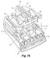
- FIG. 16 depicts the relationship of wire guide body portion 12 and insert member 41
- FIGs. 17 and 18 depict, respectively, the twisted pair management for the upper side of insert 41 and for the lower side thereof.
- the wires of each twisted pair remain twisted from within the cable 11 through the plug 10 to the IDC receiving slots 26.
- Such wire management produces consistent results in the wiring and use of each plug.
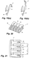
- FIGs. 19(a) and 19(b) depict the lower and the upper blade contacts 16 and 14 respectively and
- FIG. 20 is a perspective view of contact base 13 as grooved to receive the blades 14 and 16.
- the grooving for the underside of base 13 is virtually identical to the upper surface grooves shown, with the lower grooves offset approximately one IDC width from the upper groves.
- FIGs. 21, 22, and 23 depict a cover member 17 which is designed to fit over contact base 13.
- cover 17 Depending from the underside of cover 17 are four spaced latching arms 62, 63, 64, and 66, each of which has a latching projection 67, 68, 69, and 71 respectively.
- the arms 62, 63, 64, and 66 pass through the openings 35 in member 13, and openings 53 and 54 in insert 41 and latch to the projections 25 on posts 27 of the wire guide base member 12.
- members 12, 41, 13, and 17 are locked together.
- Cover 17 has mounted thereon a finger board 72 for facilitating gripping of the plug 10 when it is being inserted or withdrawn from the patch panel
- Wire guide body portion has, on either side of channel 22 L-shaped slots 73 and 74 in the top surface thereof which form, with slots 76 and 77 on the bottom surface, retaining channels for an anti-snag cover 18 shown in FIG. 24.
- cover 18 comprises a flat plate 78 having depending form its bottom surface first and second legs 79 and 81, each having, on its distal end, a boss 82 or 83.
- the bosses 82 and 83 Prior to the mounting of connector base 13 on member 12, the bosses 82 and 83 are inserted into the retaining channels through the foot of each L-shaped slot 73 and 74, and are free to move within the retaining channels.
- cover 18 When member 13 has been mounted on member 12, cover 18 is prevented from moving forward to where the bosses encounter the feet of L-shaped slots so that the cover 18, while still moveable in the retaining slots, is retained therein and cannot be removed. As shown in FIGs. 1 and 2, the anti-snag cover 18 covers the cable entrance end region of the connector 10 and effectively prevents accidental snagging thereof with external devices.
Landscapes
- Details Of Connecting Devices For Male And Female Coupling (AREA)
- Coupling Device And Connection With Printed Circuit (AREA)
Applications Claiming Priority (2)
| Application Number | Priority Date | Filing Date | Title |
|---|---|---|---|
| US09/709,163 US6325660B1 (en) | 2000-11-10 | 2000-11-10 | Low crosstalk communication connector |
| US709163 | 2000-11-10 |
Publications (3)
| Publication Number | Publication Date |
|---|---|
| EP1206015A2 true EP1206015A2 (fr) | 2002-05-15 |
| EP1206015A3 EP1206015A3 (fr) | 2003-07-16 |
| EP1206015B1 EP1206015B1 (fr) | 2005-04-13 |
Family
ID=24848731
Family Applications (1)
| Application Number | Title | Priority Date | Filing Date |
|---|---|---|---|
| EP01309508A Expired - Lifetime EP1206015B1 (fr) | 2000-11-10 | 2001-11-09 | Connecteur avec bruit diaphonique réduit |
Country Status (5)
| Country | Link |
|---|---|
| US (1) | US6325660B1 (fr) |
| EP (1) | EP1206015B1 (fr) |
| JP (1) | JP3999495B2 (fr) |
| CA (1) | CA2361883C (fr) |
| DE (1) | DE60110021T2 (fr) |
Families Citing this family (8)
| Publication number | Priority date | Publication date | Assignee | Title |
|---|---|---|---|---|
| US6811445B2 (en) | 2002-04-22 | 2004-11-02 | Panduit Corp. | Modular cable termination plug |
| US7513787B2 (en) * | 2004-01-09 | 2009-04-07 | Hubbell Incorporated | Dielectric insert assembly for a communication connector to optimize crosstalk |
| US7223112B2 (en) * | 2004-01-09 | 2007-05-29 | Hubbell Incorporated | Communication connector to optimize crosstalk |
| US7335066B2 (en) * | 2005-12-16 | 2008-02-26 | James A. Carroll | Network connector and connection system |
| WO2008027326A2 (fr) * | 2006-08-28 | 2008-03-06 | Commscope Inc. Of North Carolina | Prise de communication avec cordage réversible et configuration anti-déchirure |
| US7503799B2 (en) * | 2006-08-28 | 2009-03-17 | Commscope Inc. | Communications plug with reverse cordage and anti-snag configuration |
| US7476131B2 (en) * | 2006-09-29 | 2009-01-13 | Nellcor Puritan Bennett Llc | Device for reducing crosstalk |
| US7972183B1 (en) | 2010-03-19 | 2011-07-05 | Commscope, Inc. Of North Carolina | Sled that reduces the next variations between modular plugs |
Family Cites Families (3)
| Publication number | Priority date | Publication date | Assignee | Title |
|---|---|---|---|---|
| US5911594A (en) * | 1997-09-03 | 1999-06-15 | Lucent Technologies Inc. | Connector with wire guide |
| US5969295A (en) * | 1998-01-09 | 1999-10-19 | Commscope, Inc. Of North Carolina | Twisted pair communications cable |
| US6099345A (en) * | 1999-04-23 | 2000-08-08 | Hubbell Incorporated | Wire spacers for connecting cables to connectors |
-
2000
- 2000-11-10 US US09/709,163 patent/US6325660B1/en not_active Expired - Lifetime
-
2001
- 2001-11-09 DE DE60110021T patent/DE60110021T2/de not_active Expired - Lifetime
- 2001-11-09 CA CA002361883A patent/CA2361883C/fr not_active Expired - Fee Related
- 2001-11-09 JP JP2001343965A patent/JP3999495B2/ja not_active Expired - Fee Related
- 2001-11-09 EP EP01309508A patent/EP1206015B1/fr not_active Expired - Lifetime
Also Published As
| Publication number | Publication date |
|---|---|
| CA2361883A1 (fr) | 2002-05-10 |
| US6325660B1 (en) | 2001-12-04 |
| EP1206015A3 (fr) | 2003-07-16 |
| CA2361883C (fr) | 2006-01-03 |
| DE60110021D1 (de) | 2005-05-19 |
| DE60110021T2 (de) | 2006-03-09 |
| JP3999495B2 (ja) | 2007-10-31 |
| JP2002170631A (ja) | 2002-06-14 |
| EP1206015B1 (fr) | 2005-04-13 |
Similar Documents
| Publication | Publication Date | Title |
|---|---|---|
| US5911594A (en) | Connector with wire guide | |
| US7670193B2 (en) | Connector with insulation piercing contact and conductor guiding passageway | |
| US6083052A (en) | Enhanced performance connector | |
| US6402559B1 (en) | Modular electrical plug, plug-cable assemblies including the same, and load bar and terminal blade for same | |
| US8277260B2 (en) | Modular cable termination plug | |
| US5460545A (en) | Patch connector | |
| EP0870347B1 (fr) | Connecteur a cordon de connexion | |
| EP0793305A2 (fr) | Câble à paires torsadées et assemblage de connectuer | |
| US6663419B2 (en) | Reduced crosstalk modular plug and patch cord incorporating the same | |
| US6361354B1 (en) | Vertical and right angle modular outlets | |
| US20080014801A1 (en) | Wire guide and connector assembly using same | |
| US6325660B1 (en) | Low crosstalk communication connector | |
| US5556307A (en) | Modular telecommunication jack assembly | |
| US6368143B1 (en) | Modular plug with two piece housing | |
| CN101326685B (zh) | 插头 | |
| EP1263092B1 (fr) | Connecteur pour câble de réseau |
Legal Events
| Date | Code | Title | Description |
|---|---|---|---|
| PUAI | Public reference made under article 153(3) epc to a published international application that has entered the european phase |
Free format text: ORIGINAL CODE: 0009012 |
|
| AK | Designated contracting states |
Kind code of ref document: A2 Designated state(s): AT BE CH CY DE DK ES FI FR GB GR IE IT LI LU MC NL PT SE TR |
|
| AX | Request for extension of the european patent |
Free format text: AL;LT;LV;MK;RO;SI |
|
| PUAL | Search report despatched |
Free format text: ORIGINAL CODE: 0009013 |
|
| AK | Designated contracting states |
Designated state(s): AT BE CH CY DE DK ES FI FR GB GR IE IT LI LU MC NL PT SE TR |
|
| AX | Request for extension of the european patent |
Extension state: AL LT LV MK RO SI |
|
| 17P | Request for examination filed |
Effective date: 20031124 |
|
| 17Q | First examination report despatched |
Effective date: 20040203 |
|
| AKX | Designation fees paid |
Designated state(s): DE FR GB |
|
| GRAP | Despatch of communication of intention to grant a patent |
Free format text: ORIGINAL CODE: EPIDOSNIGR1 |
|
| GRAS | Grant fee paid |
Free format text: ORIGINAL CODE: EPIDOSNIGR3 |
|
| GRAA | (expected) grant |
Free format text: ORIGINAL CODE: 0009210 |
|
| AK | Designated contracting states |
Kind code of ref document: B1 Designated state(s): DE FR GB |
|
| REG | Reference to a national code |
Ref country code: GB Ref legal event code: FG4D |
|
| REG | Reference to a national code |
Ref country code: IE Ref legal event code: FG4D |
|
| REF | Corresponds to: |
Ref document number: 60110021 Country of ref document: DE Date of ref document: 20050519 Kind code of ref document: P |
|
| PLBE | No opposition filed within time limit |
Free format text: ORIGINAL CODE: 0009261 |
|
| STAA | Information on the status of an ep patent application or granted ep patent |
Free format text: STATUS: NO OPPOSITION FILED WITHIN TIME LIMIT |
|
| ET | Fr: translation filed | ||
| 26N | No opposition filed |
Effective date: 20060116 |
|
| PGFP | Annual fee paid to national office [announced via postgrant information from national office to epo] |
Ref country code: DE Payment date: 20101126 Year of fee payment: 10 |
|
| PGFP | Annual fee paid to national office [announced via postgrant information from national office to epo] |
Ref country code: FR Payment date: 20111128 Year of fee payment: 11 |
|
| REG | Reference to a national code |
Ref country code: FR Ref legal event code: ST Effective date: 20130731 |
|
| REG | Reference to a national code |
Ref country code: DE Ref legal event code: R119 Ref document number: 60110021 Country of ref document: DE Effective date: 20130601 |
|
| PG25 | Lapsed in a contracting state [announced via postgrant information from national office to epo] |
Ref country code: DE Free format text: LAPSE BECAUSE OF NON-PAYMENT OF DUE FEES Effective date: 20130601 |
|
| PG25 | Lapsed in a contracting state [announced via postgrant information from national office to epo] |
Ref country code: FR Free format text: LAPSE BECAUSE OF NON-PAYMENT OF DUE FEES Effective date: 20121130 |
|
| PGFP | Annual fee paid to national office [announced via postgrant information from national office to epo] |
Ref country code: GB Payment date: 20151127 Year of fee payment: 15 |
|
| GBPC | Gb: european patent ceased through non-payment of renewal fee |
Effective date: 20161109 |
|
| PG25 | Lapsed in a contracting state [announced via postgrant information from national office to epo] |
Ref country code: GB Free format text: LAPSE BECAUSE OF NON-PAYMENT OF DUE FEES Effective date: 20161109 |