EP1206025A2 - Vorrichtung zum Verpolschutz elektrischer Komponenten - Google Patents
Vorrichtung zum Verpolschutz elektrischer Komponenten Download PDFInfo
- Publication number
- EP1206025A2 EP1206025A2 EP01126165A EP01126165A EP1206025A2 EP 1206025 A2 EP1206025 A2 EP 1206025A2 EP 01126165 A EP01126165 A EP 01126165A EP 01126165 A EP01126165 A EP 01126165A EP 1206025 A2 EP1206025 A2 EP 1206025A2
- Authority
- EP
- European Patent Office
- Prior art keywords
- voltage
- switching means
- relay
- coil
- electrical
- Prior art date
- Legal status (The legal status is an assumption and is not a legal conclusion. Google has not performed a legal analysis and makes no representation as to the accuracy of the status listed.)
- Withdrawn
Links
Images
Classifications
-
- H—ELECTRICITY
- H02—GENERATION; CONVERSION OR DISTRIBUTION OF ELECTRIC POWER
- H02H—EMERGENCY PROTECTIVE CIRCUIT ARRANGEMENTS
- H02H11/00—Emergency protective circuit arrangements for preventing the switching-on in case an undesired electric working condition might result
- H02H11/002—Emergency protective circuit arrangements for preventing the switching-on in case an undesired electric working condition might result in case of inverted polarity or connection; with switching for obtaining correct connection
-
- H—ELECTRICITY
- H02—GENERATION; CONVERSION OR DISTRIBUTION OF ELECTRIC POWER
- H02J—ELECTRIC POWER NETWORKS; CIRCUIT ARRANGEMENTS OR SYSTEMS FOR SUPPLYING OR DISTRIBUTING ELECTRIC POWER; SYSTEMS FOR STORING ELECTRIC ENERGY
- H02J7/00—Circuit arrangements for charging or discharging batteries or for supplying loads from batteries
- H02J7/60—Circuit arrangements for charging or discharging batteries or for supplying loads from batteries including safety or protection arrangements
- H02J7/68—Circuit arrangements for charging or discharging batteries or for supplying loads from batteries including safety or protection arrangements using circuits for correcting or protecting against reverse-polarity
-
- H—ELECTRICITY
- H02—GENERATION; CONVERSION OR DISTRIBUTION OF ELECTRIC POWER
- H02H—EMERGENCY PROTECTIVE CIRCUIT ARRANGEMENTS
- H02H9/00—Emergency protective circuit arrangements for limiting excess current or voltage without disconnection
- H02H9/04—Emergency protective circuit arrangements for limiting excess current or voltage without disconnection responsive to excess voltage
- H02H9/045—Emergency protective circuit arrangements for limiting excess current or voltage without disconnection responsive to excess voltage adapted to a particular application and not provided for elsewhere
- H02H9/047—Free-wheeling circuits
Definitions
- the invention relates to a device for Reverse polarity protection of electrical components according to the type of independent claim.
- a motor vehicle electrical system it to reverse polarity and also to strong voltage fluctuations the supply come, which leads to destruction or Can affect certain components.
- reverse polarity protection provided, for example in the form of a diode, one Transistor, or relay with an upstream diode on Coil connection is realized. So the relay interrupts the Supply of the downstream electrical components, if the reverse polarity supply voltage over the reverse polarity Diode causes the relay to switch.
- Block sensors or this step-up converter used Block sensors or this step-up converter used.
- a generic device is described for example in DE-A 39 24 499. There is also a conventional switching power supply for a battery charger intended.
- the invention has for its object a Circuitry to specify which under warranty of the above functions are simple Structure distinguished. This task is due to the characteristics of the independent claim.
- the reverse polarity protection device has at least one connection for an electrical power supply.
- at least one reverse polarity protection agent is part a step-up circuit for and / or further electrical component.
- a Reverse polarity protection as part of the booster circuit can be the number of electrical / electronic components be reduced.
- a relay is as Reverse polarity protection used, the coil as Energy storage for the voltage boost circuit can be used.
- the coil of the Reverse polarity protection part of a step-up converter can be used.
- a switching means is expediently provided, which current flowing through the coil of the relay.
- a pulse-width-modulated control is advantageous of the switching means in such a way that the setting mean coil current is not yet one
- the switching state of the relay changes. So that is on the one hand the power supply to the coil of the relay ensured.
- the coil carries in the open State of the switching means at one of the Charging voltage stabilizing capacitor, so that its tension increases. So is just right a coil in the reverse polarity protection circuit for simultaneous Use in a booster circuit.
- MOSFET is preferably used as the switching means. This By default, MOSFET already includes a diode that acts as Reverse polarity protection diode with a reverse polarity energy supply supplied current derives and so the electrical Protects components. On the other hand, the MOSFET serves as Switching means for the booster circuit for example as a step-up converter, as already mentioned at the beginning described.
- the switching device is controlled Microcontroller. This includes the if necessary stabilizing tension. Falls below this tension the microcontroller activates a certain limit the switching means in the sense of for the voltage increase desired pulse-pause ratio.
- This Microcontroller also takes on other tasks such as for example the control of a power semiconductor, via which electrical consumers switched on and off become. A corresponding use therefore also bears this microcontroller into one for other purposes Reduction of the component effort required for this.
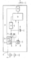
- the figure shows a block diagram of the invention Contraption.
- the positive pole of the battery 8 is connected to the input 9 of the control unit 12.
- the input 9 is electrically conductively contacted with a relay 13.
- the relay 13 consists of a coil 24 and a relay switch 22. If a sufficiently large current flows through the coil 24, the relay switch 22 is actuated in the sense of opening.
- the electrical current supplied via input 9 branches. It flows on the one hand at the polarity shown via the coil 24 and a second diode 19 in order to charge a capacitor 15, if necessary.
- the relay switch 22 when the relay switch 22 is in the closed state, the current supplied via the input 9 flows off to ground via a first diode 14 or, if a circuit breaker 10 is actuated accordingly, via a load 11.
- a switching means 18 is connected to the common potential of the coil 24 and the second diode 19.
- a polarity reversal protection diode 20 is arranged in the switching means 18 in parallel with the switch. With the polarity shown in the figure, the polarity reversal protection diode 20 is polarized in the reverse direction.
- the common potential of the relay switch 22 and the first diode 14 is detected by an analog-digital converter of a microcontroller 17.
- the microcontroller 17 in turn controls both the switching means 18 and the circuit breaker 10.
- the microcontroller 17 is supplied by a voltage stabilizer 16, which is responsible for providing the internal supply to the control device 12.
- the voltage stabilizer 16 in turn is supplied by the voltage drop across the capacitor 15.
- the relay 13 and the reverse polarity protection diode 20 integrated in the switching means 18 are used as the reverse polarity protection means.
- the polarity reversal protection diode 20 is polarized in the reverse direction, so that no current flowing through the coil 24 causing the relay switch 22 to open is flowing.
- the polarity reversal protection diode 20 is operated in the forward direction.
- a current also flows through the sink 24, which is usually so large that the relay 13 picks up, that is to say that since the relay 13 is designed as a break contact, the relay switch 22 is opened.
- the current can therefore no longer reach the electrical components such as the circuit breaker 10, the load 11 and the voltage stabilizer 16. This protects these electrical components against reverse polarity.
- the switching means 18 is a MOSFET transistor executed. With such transistors Reverse polarity protection diode 20 as an inverse diode as standard available.
- the battery 8 supplies the Relay switch 22 and the first diode 14 the capacitor 14 and thus the voltage stabilizer 16.
- the Voltage stabilizer 16 is for providing the internal supply of the control device 12 and its Microcontroller 17 is provided.
- the microcontroller 17 is now on the one hand for the control of the circuit breaker 10 responsible.
- the load 11 is connected via this circuit breaker 10 supplied with electrical energy.
- Operating signals could for example via a bus system, not shown are supplied via which the microcontroller 17th can communicate.
- the microcontroller 17 evaluates the potential or the associated voltage with which the stabilizer 16 is supplied. Is this tension below? Predeterminable limit value, the microcontroller 17 recognizes a dip in voltage. Thereupon he leads the corresponding Countermeasures that increase the voltage for a electrical component, here the stabilizer 16 serve.
- the microcontroller 17 controls the switching means 18 in the clocked operation. The pulse-pause ratio of the The control signal is selected such that the coil 24 flowing current does not open the Relay switch 22 leads. Is the switching means 18th closed, the coil 24 of the relay 13 is grounded connected.
- the coil 24 of the relay 13 tries the current which flows when the switching means 18 is activated, after the To maintain switching off of the switching means 18, so that the current stored in the coil 24 via the second Diode 19 charges the capacitor 15.
- the coil 24 of the relay 13 at this moment (switching means 18 open) itself represents a voltage source, so that due to the Series connection of the battery 8 and the coil 24 to this leads to an increased voltage on the capacitor 15. Consequently are the reverse polarity protection means 24, namely the coil 24, part a step-up circuit.
- This Booster circuit is formed in connection with the switching means 18.
- the voltage stabilizer 16 can be your own Input voltage via the pulse width modulation of the Affect switching means 18.
Landscapes
- Engineering & Computer Science (AREA)
- Power Engineering (AREA)
- Charge And Discharge Circuits For Batteries Or The Like (AREA)
- Direct Current Feeding And Distribution (AREA)
- Emergency Protection Circuit Devices (AREA)
- Relay Circuits (AREA)
Abstract
Description
-da das Relais 13 als Öffner ausgeführt ist- der Relaisschalter 22 geöffnet wird. Der Strom kann somit nicht mehr die elektrischen Komponenten wie beispielsweise den Leistungsschalter 10, die Last 11 und den Spannungsstabilisator 16 erreichen. Damit sind diese elektrischen Komponenten gegen Verpolung geschützt.
Claims (12)
- Vorrichtung zum Verpolschutz elektrischer Komponenten, mit zumindest einem Anschluß (9) für eine elektrische Energieversorgung (8), mit Verpolschutzmitteln (13, 18, 20, 22, 24), die im Falle eines verpolten Anschlusses der Energieversorgung (8) die Energiezufuhr zu zumindest einer elektrischen Komponente (10, 11, 16) beeinflussen, dadurch gekennzeichnet, dass zumindest ein Verpolschutzmittel (13, 24) Teil einer Spannungserhöhungsschaltung (13, 15, 18, 19, 24) ist zur Spannungserhöhung der elektrischen Komponente (10, 11, 16) und/oder zumindest einer weiteren elektrischen Komponente (15, 16).
- Vorrichtung nach Anspruch 1, dadurch gekennzeichnet, dass als Verpolschutzmittel ein Relais (24) vorgesehen ist.
- Vorrichtung nach einem der vorhergehenden Ansprüche, dadurch gekennzeichnet, dass als Verpolschutzmittel ein MOSFET (18) vorgesehen ist mit integrierter Diode (20) oder einem Schaltmittel mit parallelgeschalteter Diode.
- Vorrichtung nach einem der vorhergehenden Ansprüche, dadurch gekennzeichnet, dass eine Spule (24) des Relais (13) Teil der Spannungserhöhungsschaltung ist.
- Vorrichtung nach einem der vorhergehenden Ansprüche, dadurch gekennzeichnet, dass ein Schaltmittel (18) vorgesehen ist, welches im Spannungserhöhungsbetrieb das Relais (13) so ansteuert, dass ein Strom durch die Spule (24) des Relais (13) fließt, der noch keine Veränderung eines Schaltmittels (22) des Relais (13) bewirkt, welches über die Spule (24) aktivierbar ist.
- Vorrichtung nach einem der vorhergehenden Ansprüche, dadurch gekennzeichnet, dass das Schaltmittel (18) pulsweitenmoduliert angesteuert ist.
- Vorrichtung nach einem der vorhergehenden Ansprüche, dadurch gekennzeichnet, dass ein Mikrocontroller (17) vorgesehen ist, der in Abhängigkeit von einer erfaßten Spannung das Schaltmittel (18) ansteuert.
- Vorrichtung nach einem der vorhergehenden Ansprüche, dadurch gekennzeichnet, dass die Spannungserhöhungsschaltung (13, 14, 15, 18) der Spannungsversorgung eines Spannungsstabilisators (16) dient.
- Vorrichtung nach einem der vorhergehenden Ansprüche, dadurch gekennzeichnet, dass der Spannunsstabilisator (16) den Mikrocontroller (17) und/oder ein Steuergerät (12) mit Energie versorgt.
- Vorrichtung nach einem der vorhergehenden Ansprüche, dadurch gekennzeichnet, dass der Mikrocontroller (17). zumindest einen Leistungshalbleiter (10) ansteuert zur Aktivierung/Deaktivierung zumindest einer elektrischen Last (11).
- Vorrichtung nach einem der vorhergehenden Ansprüche, dadurch gekennzeichnet, dass das Schaltmittel (18) in dem Spannungsstabilisator (16) integriert ist.
- Vorrichtung nach einem der vorhergehenden Ansprüche, dadurch gekennzeichnet, dass der Spannungsstabilisator (16) die eigene Eingangsspannung über die Pulsweitenmodulation des Schaltmittels (18) beeinflusst.
Applications Claiming Priority (2)
| Application Number | Priority Date | Filing Date | Title |
|---|---|---|---|
| DE10055077A DE10055077A1 (de) | 2000-11-07 | 2000-11-07 | Vorrichtung zum Verpolschutz elektrischer Komponenten |
| DE10055077 | 2000-11-07 |
Publications (2)
| Publication Number | Publication Date |
|---|---|
| EP1206025A2 true EP1206025A2 (de) | 2002-05-15 |
| EP1206025A3 EP1206025A3 (de) | 2009-06-24 |
Family
ID=7662384
Family Applications (1)
| Application Number | Title | Priority Date | Filing Date |
|---|---|---|---|
| EP01126165A Withdrawn EP1206025A3 (de) | 2000-11-07 | 2001-11-03 | Vorrichtung zum Verpolschutz elektrischer Komponenten |
Country Status (2)
| Country | Link |
|---|---|
| EP (1) | EP1206025A3 (de) |
| DE (1) | DE10055077A1 (de) |
Cited By (3)
| Publication number | Priority date | Publication date | Assignee | Title |
|---|---|---|---|---|
| EP1429439A1 (de) * | 2002-12-05 | 2004-06-16 | International Rectifier Corporation | Verpolschutzschaltung |
| WO2010094514A1 (de) * | 2009-02-18 | 2010-08-26 | Auto-Kabel Managementgesellschaft Mbh | Verpolschutzeinrichtung |
| EP2442419A2 (de) | 2010-10-15 | 2012-04-18 | Schneider Electric Industries SAS | Schutz für den Anschluss einer Gleichstromquelle an ein elektronisches Gerät |
Citations (1)
| Publication number | Priority date | Publication date | Assignee | Title |
|---|---|---|---|---|
| US6023418A (en) | 1999-04-29 | 2000-02-08 | Cardiac Evaluation Center, Inc. | Low voltage polarity correcting DC to DC converter |
Family Cites Families (5)
| Publication number | Priority date | Publication date | Assignee | Title |
|---|---|---|---|---|
| DE3924499B4 (de) * | 1989-07-25 | 2006-10-19 | Matthias Schulze | Verfahren zum Laden von Akkumulatoren und Ladegerät hierfür |
| DE29824874U1 (de) * | 1998-07-10 | 2003-04-30 | Ellenberger & Poensgen GmbH, 90518 Altdorf | Schutzschalteinrichtung |
| JP3545721B2 (ja) * | 2001-04-02 | 2004-07-21 | 株式会社小糸製作所 | 保護装置 |
| DE102005007123A1 (de) * | 2005-02-17 | 2006-08-24 | Audi Ag | Bordnetz mit Tiefsetzsteller für ein Kraftfahrzeug |
| US7312653B2 (en) * | 2005-03-10 | 2007-12-25 | Gm Global Technology Operations, Inc. | NMOS reverse battery protection |
-
2000
- 2000-11-07 DE DE10055077A patent/DE10055077A1/de not_active Withdrawn
-
2001
- 2001-11-03 EP EP01126165A patent/EP1206025A3/de not_active Withdrawn
Patent Citations (1)
| Publication number | Priority date | Publication date | Assignee | Title |
|---|---|---|---|---|
| US6023418A (en) | 1999-04-29 | 2000-02-08 | Cardiac Evaluation Center, Inc. | Low voltage polarity correcting DC to DC converter |
Cited By (4)
| Publication number | Priority date | Publication date | Assignee | Title |
|---|---|---|---|---|
| EP1429439A1 (de) * | 2002-12-05 | 2004-06-16 | International Rectifier Corporation | Verpolschutzschaltung |
| US6969971B2 (en) | 2002-12-05 | 2005-11-29 | International Rectifier Corporation | Reverse battery protection circuit |
| WO2010094514A1 (de) * | 2009-02-18 | 2010-08-26 | Auto-Kabel Managementgesellschaft Mbh | Verpolschutzeinrichtung |
| EP2442419A2 (de) | 2010-10-15 | 2012-04-18 | Schneider Electric Industries SAS | Schutz für den Anschluss einer Gleichstromquelle an ein elektronisches Gerät |
Also Published As
| Publication number | Publication date |
|---|---|
| DE10055077A1 (de) | 2002-05-29 |
| EP1206025A3 (de) | 2009-06-24 |
Similar Documents
| Publication | Publication Date | Title |
|---|---|---|
| DE10296400B4 (de) | Aufwecksystem für auf einem Fahrzeug unterstützte elektronische Komponenten | |
| DE10057259A1 (de) | Mehrspannungsbordnetz für ein Kraftfahrzeug | |
| DE102007050844A1 (de) | Booster-Leistungsschaltkreis | |
| WO2006021511A1 (de) | Spannungsregler mit überspannungsschutz | |
| DE102008045968A1 (de) | Stromversorgungs-Steuergerät | |
| EP2609322B1 (de) | Verfahren und vorrichtung zum betreiben eines starters eines fahrzeugs | |
| EP0314681B1 (de) | Endstufe in brückenschaltung | |
| EP1299933B1 (de) | Elektronische schaltung für ein energieversorgungsgerät, insbesondere für ein ladegerät für akkumulatoren | |
| DE112018004725T5 (de) | Stromfluss-Steuereinrichtung | |
| EP0492103B1 (de) | Einrichtung zur Spannungsversorgung bei Geräten mit Nachlauf | |
| DE102004007181A1 (de) | Lasttreiberschaltkreis | |
| EP0461432A2 (de) | Vorrichtung zum Ein- und Ausschalten einer Last | |
| EP1249066A1 (de) | Schaltungsanordnung und elektrogerät mit einer induktiven last und einem drosselwandler | |
| DE69207455T2 (de) | Schaltkreis zur Erkennung eines Schalterzustandes, namentlich eines Zündschlüssels in einem Spannungsregler eines Wechselstromgenerators | |
| DE102013218627B3 (de) | Vorrichtung zum Aktivieren eines elektronischen Gerätes, insbesondere eines Steuergerätes in einem Fahrzeug | |
| EP1206025A2 (de) | Vorrichtung zum Verpolschutz elektrischer Komponenten | |
| DE3238899A1 (de) | Kurzschlussfeste ansteuerschaltung fuer einen elektrischen verbraucher | |
| DE10008265A1 (de) | Elektronische Schaltvorrichtung mit einem Batterieschalter und einem Standby-Schalter | |
| WO2002047235A1 (de) | Vorrichtung zur fehlererkennung in einem mehrspannungsbordnetz | |
| EP1825529B1 (de) | Elektrische schaltung zur ansteuerung eines piezoelektrischen elements insbesondere einer kraftstoffeinspritzanlage eines kraftfahrzeugs | |
| DE10349629B4 (de) | Elektronischer Schaltkreis | |
| DE102006046032B3 (de) | Steuervorrichtung mit Klemme 15-Halteschaltung | |
| EP2414188B1 (de) | Anordnung zur bereitstellung elektrischer energie | |
| DE102015015461B4 (de) | Vorrichtung und Verfahren zum Schalten eines Stromes in einer elektrischen Versorgungsleitung sowie Kraftfahrzeug | |
| DE102019217893A1 (de) | Schaltnetzteilvorrichtung |
Legal Events
| Date | Code | Title | Description |
|---|---|---|---|
| PUAI | Public reference made under article 153(3) epc to a published international application that has entered the european phase |
Free format text: ORIGINAL CODE: 0009012 |
|
| AK | Designated contracting states |
Kind code of ref document: A2 Designated state(s): AT BE CH CY DE DK ES FI FR GB GR IE IT LI LU MC NL PT SE TR |
|
| AX | Request for extension of the european patent |
Free format text: AL;LT;LV;MK;RO;SI |
|
| PUAL | Search report despatched |
Free format text: ORIGINAL CODE: 0009013 |
|
| AK | Designated contracting states |
Kind code of ref document: A3 Designated state(s): AT BE CH CY DE DK ES FI FR GB GR IE IT LI LU MC NL PT SE TR |
|
| AX | Request for extension of the european patent |
Extension state: AL LT LV MK RO SI |
|
| RIC1 | Information provided on ipc code assigned before grant |
Ipc: H02J 7/00 20060101ALI20090519BHEP Ipc: H02H 11/00 20060101AFI20020208BHEP |
|
| 17P | Request for examination filed |
Effective date: 20091228 |
|
| AKX | Designation fees paid |
Designated state(s): DE FR GB IT |
|
| 17Q | First examination report despatched |
Effective date: 20101105 |
|
| STAA | Information on the status of an ep patent application or granted ep patent |
Free format text: STATUS: THE APPLICATION IS DEEMED TO BE WITHDRAWN |
|
| 18D | Application deemed to be withdrawn |
Effective date: 20120601 |