EP1206127A2 - Dispositif de prise d'images - Google Patents
Dispositif de prise d'images Download PDFInfo
- Publication number
- EP1206127A2 EP1206127A2 EP01308976A EP01308976A EP1206127A2 EP 1206127 A2 EP1206127 A2 EP 1206127A2 EP 01308976 A EP01308976 A EP 01308976A EP 01308976 A EP01308976 A EP 01308976A EP 1206127 A2 EP1206127 A2 EP 1206127A2
- Authority
- EP
- European Patent Office
- Prior art keywords
- charge detection
- image pickup
- circuit
- solid
- ccds
- Prior art date
- Legal status (The legal status is an assumption and is not a legal conclusion. Google has not performed a legal analysis and makes no representation as to the accuracy of the status listed.)
- Withdrawn
Links
Images




Classifications
-
- H—ELECTRICITY
- H10—SEMICONDUCTOR DEVICES; ELECTRIC SOLID-STATE DEVICES NOT OTHERWISE PROVIDED FOR
- H10F—INORGANIC SEMICONDUCTOR DEVICES SENSITIVE TO INFRARED RADIATION, LIGHT, ELECTROMAGNETIC RADIATION OF SHORTER WAVELENGTH OR CORPUSCULAR RADIATION
- H10F39/00—Integrated devices, or assemblies of multiple devices, comprising at least one element covered by group H10F30/00, e.g. radiation detectors comprising photodiode arrays
- H10F39/10—Integrated devices
- H10F39/12—Image sensors
- H10F39/15—Charge-coupled device [CCD] image sensors
- H10F39/151—Geometry or disposition of pixel elements, address lines or gate electrodes
- H10F39/1515—Optical shielding
-
- H—ELECTRICITY
- H04—ELECTRIC COMMUNICATION TECHNIQUE
- H04N—PICTORIAL COMMUNICATION, e.g. TELEVISION
- H04N25/00—Circuitry of solid-state image sensors [SSIS]; Control thereof
- H04N25/40—Extracting pixel data from image sensors by controlling scanning circuits, e.g. by modifying the number of pixels sampled or to be sampled
- H04N25/44—Extracting pixel data from image sensors by controlling scanning circuits, e.g. by modifying the number of pixels sampled or to be sampled by partially reading an SSIS array
- H04N25/443—Extracting pixel data from image sensors by controlling scanning circuits, e.g. by modifying the number of pixels sampled or to be sampled by partially reading an SSIS array by reading pixels from selected two-dimensional [2D] regions of the array, e.g. for windowing or digital zooming
-
- H—ELECTRICITY
- H04—ELECTRIC COMMUNICATION TECHNIQUE
- H04N—PICTORIAL COMMUNICATION, e.g. TELEVISION
- H04N25/00—Circuitry of solid-state image sensors [SSIS]; Control thereof
- H04N25/70—SSIS architectures; Circuits associated therewith
- H04N25/76—Addressed sensors, e.g. MOS or CMOS sensors
-
- H—ELECTRICITY
- H04—ELECTRIC COMMUNICATION TECHNIQUE
- H04N—PICTORIAL COMMUNICATION, e.g. TELEVISION
- H04N25/00—Circuitry of solid-state image sensors [SSIS]; Control thereof
- H04N25/70—SSIS architectures; Circuits associated therewith
- H04N25/76—Addressed sensors, e.g. MOS or CMOS sensors
- H04N25/78—Readout circuits for addressed sensors, e.g. output amplifiers or A/D converters
-
- H—ELECTRICITY
- H10—SEMICONDUCTOR DEVICES; ELECTRIC SOLID-STATE DEVICES NOT OTHERWISE PROVIDED FOR
- H10F—INORGANIC SEMICONDUCTOR DEVICES SENSITIVE TO INFRARED RADIATION, LIGHT, ELECTROMAGNETIC RADIATION OF SHORTER WAVELENGTH OR CORPUSCULAR RADIATION
- H10F39/00—Integrated devices, or assemblies of multiple devices, comprising at least one element covered by group H10F30/00, e.g. radiation detectors comprising photodiode arrays
- H10F39/10—Integrated devices
- H10F39/12—Image sensors
- H10F39/15—Charge-coupled device [CCD] image sensors
- H10F39/153—Two-dimensional or three-dimensional array CCD image sensors
- H10F39/1534—Interline transfer
-
- H—ELECTRICITY
- H10—SEMICONDUCTOR DEVICES; ELECTRIC SOLID-STATE DEVICES NOT OTHERWISE PROVIDED FOR
- H10F—INORGANIC SEMICONDUCTOR DEVICES SENSITIVE TO INFRARED RADIATION, LIGHT, ELECTROMAGNETIC RADIATION OF SHORTER WAVELENGTH OR CORPUSCULAR RADIATION
- H10F39/00—Integrated devices, or assemblies of multiple devices, comprising at least one element covered by group H10F30/00, e.g. radiation detectors comprising photodiode arrays
- H10F39/10—Integrated devices
- H10F39/12—Image sensors
- H10F39/15—Charge-coupled device [CCD] image sensors
- H10F39/153—Two-dimensional or three-dimensional array CCD image sensors
- H10F39/1536—Frame transfer
Definitions
- the present invention relates to an image pickup apparatus for picking up an object image.
- CCD-type elements Conventional solid-state image pickup elements are mainly classified into CCD-type elements and CMOS-type elements.
- CCD-type elements are an interline CCD (IL-CCD) and frame transfer CCD (FT-CCD).
- An interline CCD comprises a plurality of photoelectric conversion units, vertical CCDs, transfer gates for transferring signal charges in the photoelectric conversion units to the vertical CCDs, a horizontal CCD for horizontally transferring the charges from the vertical CCDs, and a floating diffusion amplifier (FD-Amp).
- a frame transfer CCD comprises photoelectric conversion units, a storage unit to which charges in the photoelectric conversion units are transferred (frame-shifted), a horizontal transfer unit for horizontally transferring the charges from the storage unit, and a floating diffusion amplifier (FD-Amp).
- Fig. 11 shows an IL-CCD as a typical example of a CCD-type solid-state image pickup element.
- an IL-CCD comprises photoelectric conversion units (PDs) 70, vertical CCDs (V-CCDs) 71 for temporarily storing charges from the photoelectric conversion units 70, a horizontal CCD (H-CCD) 72 for receiving the charges from the vertical CCDs 71 and transferring the charges in the horizontal direction, and a floating diffusion amplifier (FD-Amp) 73 serving as an output amplifier for converting the charges from the horizontal CCD 72 into a voltage.
- PDs photoelectric conversion units
- V-CCDs vertical CCDs
- H-CCD horizontal CCD
- FD-Amp floating diffusion amplifier
- the CCD has low noise level because signal charges are completely transferred to the FD-Amp on the output side.
- the pixel size can be made small because of the simple pixel structure.
- the power consumption of a horizontal CCD drive circuit is high (up to CfV 2 ).
- a CDS circuit for reducing reset noise in an FD-Amp requires a sampling accuracy on the order of nsec, that sampling accuracy cannot be ensured because of the mass production and the wide range of use conditions (temperature and a variation in voltage). Hence, a low-noise CCD can hardly be implemented.
- each pixel unit 80 comprises a photoelectric conversion unit PD and a MOS transistor serving as a pixel amplifier.
- the pixels are selected and driven by a random-accessible vertical scanning circuit 81 and horizontal scanning circuit 85, resulting in functional advantage.
- Charges in each pixel unit 80 are converted into a voltage by the pixel amplifier, output to a clamp circuit 83 through a vertical signal line 82, and after noise removal from the pixel unit amplifier by the clamp circuit 83, output to a horizontal signal line 84.
- the signals are sequentially output by the horizontal scanning circuit 85 from the horizontal signal line 84 through an amplifier (Amp) 86.
- Amp amplifier
- CMOS sensor sequentially selects and outputs each pixel signal by the horizontal scanning circuit 85, unlike charge transfer as in a CCD, the power consumption is low. However, since the number of elements of each pixel unit is large, it is difficult to reduce the pixel size.
- a CCD is advantageous in increasing the number of pixels but disadvantageous in high-speed drive and power consumption.
- a CMOS sensor is disadvantageous in increasing the number of pixels but advantageous in high-speed drive and power consumption.
- an image pickup apparatus comprising:
- an image pickup apparatus comprising:
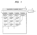
- Fig. 1 is a schematic view showing a solid-state image pickup element according to the first embodiment of the present invention.
- Object light is photoelectrically converted by photodiodes (PDs) 1 each serving as a photoelectric conversion unit.
- the photodiodes 1 are arrayed in a matrix form as pixels P 11 , P 12 , P 13 ,..., P 21 , P 22 , P 23 ,..., P 31 , P 32 , P 33 ,....
- Charges photoelectrically converted by the photodiodes 1 are transferred to vertical CCDs 2 through transfer gates.
- the charges transferred to the vertical CCDs 2 are transferred to charge detection circuits 3 and converted into a voltage at once every horizontal period.
- the interline CCD unit is formed from the photodiodes 1 and vertical CCDs 2. Unlike the conventional interline CCD shown in Fig. 11, signal charges from the vertical CCDs are transferred (not to the horizontal CCD) to the charge detection circuits 3.
- the signal voltage is output to a horizontal signal line 5 in accordance with a pulse from a horizontal scanning circuit 4 and guided to an image signal processing circuit (not shown) on the output side through an output amplifier 6.
- the output signal from each charge detection circuit 3 may be directly read out.
- a signal processing means for executing signal processing such as noise removal or A/D conversion may be provided on the output side of each charge detection circuit 3 and the signal may be output by the horizontal scanning circuit 4.
- the solid-state image pickup element shown in Fig. 1 is formed on a single semiconductor chip.
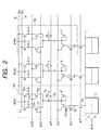
- Fig. 2 is a schematic view of the charge detection circuit and signal processing circuit shown in Fig. 1.
- the charge detection circuit comprises a charge detection amplifier (FD-Amp; floating diffusion amplifier) having a gate to which signal charges from the vertical CCD are transferred, and a reset transistor TR for resetting the gate of the charge detection amplifier.
- the signal processing circuit comprises a clamp capacitor Cp for removing noise, a transistor Tp, storage capacitors C S1 and C S2 for storing signals after noise removal, transfer transistors T S1 and T S2 for connecting the clamp capacitor Cp to the storage capacitors C S1 and C S2 , and transistors T C1 and T C2 for outputting signals from the storage capacitors C S1 and C S2 to horizontal signal lines 5 1 and 5 2 .
- These components form a charge detection/signal processing block 100.
- the vertical CCD 2 transfers charges to the charge detection amplifier (FD-Amp; floating diffusion amplifier) through a transfer gate TG every horizontal period in accordance with a drive pulse ⁇ Vn.
- the charge detection amplifier (FD-Amp) reset noise is generated by a parasitic capacitance and the reset transistor TR for removing residual voltage (charges) in the gate unit.
- the offset voltage fluctuates among the charge detection amplifiers (FD-Amps). To remove these noise components, the noise is clamped by the clamp capacitor Cp before the charges are transferred from the vertical CCD 2 to the charge detection amplifier (FD-Amp).
- the transfer gate TG is turned on to transfer the charges in the vertical CCD 2 (signal charges from the pixels P 11 , P 12 , P 13 ,...) to the gate unit of the charge detection amplifier (FD-Amp) and converted into a voltage by its parasitic capacitance.
- the above-described reset noise and offset voltage are superposed on the output signal voltage from the charge detection amplifier. Since the noise components are clamped by the clamp capacitor Cp, the noise is consequently removed at the output terminal of the clamp capacitor Cp, and only the signal voltage is stored in the storage capacitor C S1 .
- next charges in the vertical CCD 2 (signal charges from the pixels P 21 , P 22 , P 23 , ...) are converted into a voltage and, after noise removal, stored in the storage capacitor C S2 .
- Pixel signals S 01 and S 02 of two rows which are stored in the storage capacitors C S1 and C S2 are sequentially transferred to the horizontal signal lines 5 1 and 5 2 in accordance with a scanning pulse from the horizontal scanning circuit 4.
- Fig. 3 is an operation timing chart of the charge detection circuit and signal processing circuit shown in Fig. 2.
- the drive pulse ⁇ Vn goes high during a period T 1 to transfer charges to the vertical CCD 2 on the input side of the transfer gate TG.
- a power supply voltage Vcc of the charge detection amplifier (FD-Amp) is applied, a signal ⁇ C goes high to reset the gate of the charge detection amplifier (FD-Amp), a signal ⁇ P goes high to turn on the transistor Tp, the output terminal of the clamp capacitor Cp is clamped to the reference voltage, and signals ⁇ S1 and ⁇ S2 go high to reset the residual charges in the storage capacitors C S1 and C S2 .
- reset noise and offset voltage components are clamped by the clamp capacitor Cp.
- a signal ⁇ T goes high to turn on the transfer gate TG and transfer the signal charges to the gate portion of the charge detection amplifier.
- the above-described reset noise and offset voltage are superposed on the output signal voltage from the charge detection amplifier.
- the noise is consequently removed at the output terminal of the clamp capacitor Cp, and the signal ⁇ S1 goes high, so that the pixel signal of a row V 1 , from which noise has been removed, is stored in the storage capacitor C S1 .
- the power supply voltage Vcc of the charge detection amplifier is turned off to prevent power consumption.
- the charge detection amplifier operates at a low speed in one horizontal scanning period, the frequency bandwidth is small. For this reason, noise generated in the amplifier is much smaller than in the output amplifier of a general CCD.
- CDS noise removing operation
- the time required for reset operation of the FD-Amp and charge transfer from the vertical CCD is preferably short.
- the signals stored in the storage capacitors C S1 and C S2 are sequentially output during a next period T 6 in accordance with a scanning pulse ⁇ Hmn ( ⁇ H 01 , ⁇ H 02 , ⁇ H 03 ,...) from the horizontal scanning circuit 4. That is, since the signal is selected and output on the each pixel signal basis, the power consumption of the horizontal scanning circuit is low. In addition, since pixel signals of two rows can be simultaneously output, high-speed drive can be performed. If drive at a higher speed is necessary, the number of memories (storage capacitors) is increased to execute multiple-line output.
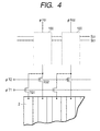
- Fig. 4 shows a solid-state image pickup element according to the second embodiment of the present invention. Circuits in a charge detection/signal processing block 100, which are identical to those in Fig. 2, are not illustrated in Fig. 4.
- charges in a plurality of vertical CCDs 2 are sequentially output using a common charge detection amplifier.
- Signals ⁇ T1 and ⁇ T2 are sequentially set to H level to turn on transfer gates T G1 and T G2 to sequentially control charge transfer from vertical CCDs of two columns to the charge detection amplifier whereby pixel signals of two columns are stored in storage capacitors C S1 and C S2 and output.
- the charge detection circuit and signal processing circuit can be formed in the width of two pixels, the chip area can be decreased.
- the signal processing circuit can have a programmable gain amplifier, A/D conversion circuit, and for a color sensor, a white balance circuit, and the like.
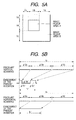
- Figs. 5A and 5B are explanatory views of the third embodiment related to random access drive.
- This embodiment has the same arrangement as described above except a horizontal scanning circuit 4, and as its characteristic feature, the solid-state image pickup element is a random-accessible solid-state image pickup element.
- Fig. 5A is a view showing an image pickup surface
- Fig. 5B is a timing chart of an image read from an image pickup area A.
- An image pickup area includes the image pickup areas A and B.
- drive is performed using almost the same frequency for both the vertical and horizontal scanning periods.
- high-speed drive can be performed when only the image pickup area A that should be read out is read out.
- the conventional CCD it is difficult to read out the image pickup area A to be read out at a high speed.
- the vertical CCD is driven at a high speed to remove unnecessary charges by a reset transistor TR of the charge detection amplifier.
- a random-accessible horizontal scanning circuit is arranged to execute scanning to output a signal only during a period H B .
- a decoder or a shift register which is divided into a plurality of areas and can start on each area basis is used. As a result, only the image signal in the image pickup area A can be read out. For this reason, high-speed drive can be achieved, and the power consumption can be reduced because the unnecessary image pickup area is not driven.
- More developed random access can be realized by a CCD capable of selecting a pixel row.
- a CCD capable of selecting a pixel row.
- an element is disclosed in the Institute of Image Information and Television Engineers technical report TEBS 101-6 ED 841.
- This known example is called a charge sweep device in which pixel row selection is driven by a vertical TG-SCANNER.
- the technological advantages of this embodiment can be expected.
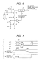
- FIG. 6 is a block diagram of an equivalent circuit having a charge detection circuit and sequential-comparison-type A/D conversion circuit unit.
- a D/A converter receives DA output range switching information used to switch the range of the ramp-shaped reference voltage.
- the circuit comprises a vertical CCD 2, a transfer gate 42 for transferring signal charges from the vertical CCD 2 to the gate of an FD-Amp (floating diffusion amplifier) 43, a selection transistor 44, a reset transistor 45, a current supply transistor 46 for storing, as a voltage, the output current from the FD-Amp 43 by a switch 47 and storage capacitor 48 and outputting the voltage while converting it into a current, a comparator 51 for detecting the difference between the output current from the current supply transistor 46 and the output current from the FD-Amp 43 through the selection transistor 44, a counter 50 for counting the output from the comparator 51, and a D/A converter 49 for outputting a voltage to the source (main electrode) terminal of the FD-Amp 43 in accordance with a digital signal output from the counter 50.
- the D/A converter 49 receives DA output range switching information to switch the range of the ramp-shaped reference voltage to be output from the D/A converter 49 such that the pixel signal has an optimum value within the
- a method of obtaining a signal voltage by signal charges from the vertical CCD after the FD-Amp is reset in the above arrangement will be described as an example with reference to the timing chart shown in Fig. 7.
- the description below will be made while assuming that the transistors 42, 43, 44, and 45 shown in Fig. 6 are PMOS transistors, and the transistor 46 is an NMOS transistor.
- the D/A converter 49 is set to output a high potential (V HD ). Assume that the counter 50 is reset and no count operation is being performed.
- a signal ⁇ c is set to "L" level (pulse 201) to turn on the reset transistor 45 to reset the gate terminal of the FD-Amp 43 to a predetermined potential.
- a signal ⁇ x is set to "L" level (pulse 202) to turn on the selection transistor 44 and also turn on the switch 47.
- the output current from the FD-Amp 43 at the time of reset is stored in the storage capacitor 48 as a gate voltage generated when the gate and drain of the transistor 46 short-circuit (the comparison reference voltage is stored).
- the transistors 45 and 44 and switch 47 are turned off, and a signal ⁇ T is set to "L" level (pulse 203) to turn on the transfer gate 42 to transfer signal charges from the vertical CCD to the gate terminal of the FD-Amp 43.
- the output current from the FD-Amp 43 has a larger value than at the time of reset.
- the transistor 46 receives the voltage from the storage capacitor 48 and outputs the current when the FD-Amp 43 is reset.
- the signal ⁇ X is set to "L" level (pulse 204) to turn on the transistor 44 again, the input potential of the comparator 51 rises to a high potential (V H ).
- the counter 50 is operated, and its digital output is amplified.
- the output voltage from the D/A converter 49 that receives the output from the counter 50 gradually decreases (assume that the D/A converter 49 generates a negative analog output voltage with respect to the digital input signal).
- the output current from the FD-Amp 43 becomes equal to that from the transistor 46, and the input voltage to the comparator 51 abruptly decreases.
- the count operation of the counter 50 is stopped.
- the digital value that has changed during a period from the start to the end of counting by the counter 50 equals to the difference between the gate potential of the FD-Amp 43 at the time of reset and the potential when the signal charges are transferred. In this way, A/D conversion is executed correspondingly to the difference.
- Fig. 8 is a schematic circuit diagram showing connection between the vertical CCD and the charge detection circuit and A/D conversion circuit.
- the same reference numerals as in Fig. 6 denote the same members in Fig. 8.
- the signal charges from the vertical CCD 2 are input to the gate of the FD-Amp 43, converted into digital data by the counter 50, sequentially selected by a data selector 52, and output as A/D-converted data.
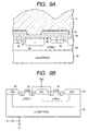
- Figs. 9A and 9B are sectional views showing the structure of a solid-state image pickup element according to the fifth embodiment.
- Fig. 9A is a sectional view showing the structure of a photoelectric conversion unit, vertical CCD, and channel stop.
- Fig. 9B is a sectional view showing the structure of an inverter unit that forms part of a signal processing circuit.
- a unit pixel is formed from a PD region serving as a photoelectric conversion unit, a transfer gate region for transferring charges, a vertical CCD region, and a channel stop region. These regions are formed in a p-well 65 formed on an n-substrate 60. In the PD region, a dark current is reduced by a p + -layer 67 on the surface. In the vertical CCD region, a p-layer 68 is formed under an n-layer 69 to reduce an increase and smearing in transfer charge amount. In the transfer gate region, control is executed to transfer photocharges from the PD to the vertical CCD.
- the solid-state image pickup element also has a microlens 61 for focusing light in the PD region, a light-shielding layer 62, a gate electrode 63 made of polysilicon, and an SiO 2 layer 64.
- a p-well and n-well are formed on the n-substrate 60 to form an NMOS transistor and PMOS transistor.
- Well separation between the CCD unit and the signal processing circuit unit is preferably done from the charge detection circuit unit. This is because the signal processing circuit unit generates pulse noise due to high-speed signal transfer or the logic circuit. To prevent noise from propagating from the noise source to the CCD unit, the CCD unit and signal processing circuit are separated by the well.
- the charge detection circuit unit may be formed in the CCD well. Since the charge detection circuit unit has a function of converting signal charges into a voltage every horizontal period and therefore operates at a low speed, it generates little noise.
- Fig. 13 shows a structure in which the inverter unit is separated by a deep well. When the inverter unit is completely separated from the sensor unit, noise from the inverter unit can be more effectively shielded.
- the solid-state image pickup element of this embodiment can have any one of the equivalent circuits of the first to fourth embodiments.
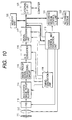
- the camera has a barrier 111 serving as the protection and main switch of a lens, a lens 112 for forming an optical image of an object onto a solid-state image pickup element 114, an iris 113 for changing the amount of light transmitted through the lens 112, the solid-state image pickup element 114 for receiving the object image formed by the lens 112 to output an image signal, an image pickup signal processing circuit 115, an A/D converter 116 for executing A/D conversion of the image signal output from the image pickup signal processing circuit 115, a signal processing unit 117 for executing various kinds of correction operations for the image data output from the A/D converter 116 or compressing the data, a timing generation unit 118 for outputting various kinds of timing signals to the solid-state image pickup element 114, image pickup signal processing circuit 115, A/D converter 116, and signal processing unit 117, a system control and operation unit 119 for executing various kinds of operations and controlling the entire still video camera, a memory unit 120 for temporarily storing the image data, an interface
- the system control and operation unit 119 sets the iris 113 in the full-aperture state.
- the signal output from the solid-state image pickup element 114 is converted by the A/D converter 116 and input to the signal processing unit 117.
- the system control and operation unit 119 executes calculation for exposure on the basis of the data.
- the brightness is determined on the basis of the result of photometry, and in accordance with the result, the system control and operation unit 119 controls the iris.
- the lens On the basis of the signal output from the solid-state image pickup element 114, a high-frequency component is extracted, and the distance to the object is calculated by the system control and operation unit 119. After that, the lens is driven, and it is determined whether an in-focus state is obtained. If it is determined that no in-focus state is obtained, the lens is driven again, and distance measurement is performed. After confirming the in-focus state, actual exposure starts.
- the image signal output from the solid-state image pickup element 114 is A/D-converted by the A/D converter 116, passes through the signal processing unit 117, and is written in the memory unit by the system control and operation unit 119.
- the data stored in the memory unit 120 is recorded on the detachable recording medium 122 such as a semiconductor memory through the recording medium control I/F unit 121 under the control of the system control and operation unit 119.
- the image data may be directly input to a computer or the like through the external I/F unit 123 to process the image.
- a sensitive image pickup apparatus capable of high-performance function, high-speed drive, and power consumption reduction can be provided.
Landscapes
- Engineering & Computer Science (AREA)
- Multimedia (AREA)
- Signal Processing (AREA)
- Solid State Image Pick-Up Elements (AREA)
- Transforming Light Signals Into Electric Signals (AREA)
Applications Claiming Priority (2)
| Application Number | Priority Date | Filing Date | Title |
|---|---|---|---|
| JP2000324451A JP3937716B2 (ja) | 2000-10-24 | 2000-10-24 | 固体撮像装置及び撮像システム |
| JP2000324451 | 2000-10-24 |
Publications (2)
| Publication Number | Publication Date |
|---|---|
| EP1206127A2 true EP1206127A2 (fr) | 2002-05-15 |
| EP1206127A3 EP1206127A3 (fr) | 2009-08-05 |
Family
ID=18801984
Family Applications (1)
| Application Number | Title | Priority Date | Filing Date |
|---|---|---|---|
| EP01308976A Withdrawn EP1206127A3 (fr) | 2000-10-24 | 2001-10-23 | Dispositif de prise d'images |
Country Status (3)
| Country | Link |
|---|---|
| US (2) | US7145600B2 (fr) |
| EP (1) | EP1206127A3 (fr) |
| JP (1) | JP3937716B2 (fr) |
Families Citing this family (19)
| Publication number | Priority date | Publication date | Assignee | Title |
|---|---|---|---|---|
| JP4298964B2 (ja) * | 2002-05-16 | 2009-07-22 | 富士フイルム株式会社 | 固体撮像素子及びその製造方法 |
| JP2004266363A (ja) * | 2003-02-18 | 2004-09-24 | Sony Corp | 撮像装置及び撮像装置の駆動方法 |
| JP2005101486A (ja) * | 2003-08-28 | 2005-04-14 | Sanyo Electric Co Ltd | 固体撮像素子及びその制御方法 |
| KR20050077434A (ko) * | 2004-01-28 | 2005-08-02 | 삼성전자주식회사 | 소비 전력을 줄일 수 있는 고체 촬상 장치 |
| JP4144535B2 (ja) * | 2004-03-03 | 2008-09-03 | ソニー株式会社 | 固体撮像装置、画素信号読出方法 |
| JP4742523B2 (ja) * | 2004-06-14 | 2011-08-10 | ソニー株式会社 | 固体撮像素子及びその駆動方法 |
| JP2006041196A (ja) * | 2004-07-27 | 2006-02-09 | Nec Electronics Corp | 固体撮像素子およびその製造方法 |
| JP2006049986A (ja) * | 2004-07-30 | 2006-02-16 | Sony Corp | 固体撮像装置 |
| JP4825982B2 (ja) * | 2005-06-29 | 2011-11-30 | 国立大学法人 奈良先端科学技術大学院大学 | 固体撮像素子及びその信号読み出し方法 |
| JP4542962B2 (ja) | 2005-07-21 | 2010-09-15 | 富士フイルム株式会社 | デジタルカメラ |
| JP4740781B2 (ja) * | 2006-03-30 | 2011-08-03 | 富士フイルム株式会社 | 固体撮像装置 |
| JP2008118434A (ja) * | 2006-11-06 | 2008-05-22 | Fujifilm Corp | 固体撮像素子及び撮像装置 |
| JPWO2008142968A1 (ja) * | 2007-05-21 | 2010-08-05 | 株式会社島津製作所 | 撮像素子およびそれを備えた撮像装置 |
| JP5202395B2 (ja) * | 2009-03-09 | 2013-06-05 | 株式会社半導体エネルギー研究所 | タッチパネル、電子機器 |
| JP5941659B2 (ja) | 2011-11-02 | 2016-06-29 | 浜松ホトニクス株式会社 | 固体撮像装置 |
| JP5917883B2 (ja) | 2011-11-02 | 2016-05-18 | 浜松ホトニクス株式会社 | 固体撮像装置 |
| JP5812959B2 (ja) * | 2011-12-15 | 2015-11-17 | キヤノン株式会社 | 撮像装置 |
| JP5924924B2 (ja) | 2011-12-15 | 2016-05-25 | キヤノン株式会社 | 電子回路 |
| JP6623734B2 (ja) * | 2015-12-14 | 2019-12-25 | セイコーエプソン株式会社 | 画像読取装置及び半導体装置 |
Citations (3)
| Publication number | Priority date | Publication date | Assignee | Title |
|---|---|---|---|---|
| JPH0697414A (ja) | 1992-09-11 | 1994-04-08 | Hitachi Ltd | 固体撮像装置 |
| US5449908A (en) | 1993-12-30 | 1995-09-12 | Texas Instruments Incorporated | Hybrid CCD imaging |
| US5898509A (en) | 1996-10-15 | 1999-04-27 | Hewlett-Packard Company | Method for improving the signal-to-noise ratio of a CCD sensor in a color imaging device |
Family Cites Families (31)
| Publication number | Priority date | Publication date | Assignee | Title |
|---|---|---|---|---|
| US4985758A (en) * | 1982-12-07 | 1991-01-15 | Canon Kabushiki Kaisha | Signal processing system having selected output from plural readout devices |
| CA1269446C (fr) * | 1984-12-28 | 1990-05-22 | Appareil de prise de vues | |
| US4914519A (en) * | 1986-09-19 | 1990-04-03 | Canon Kabushiki Kaisha | Apparatus for eliminating noise in a solid-state image pickup device |
| EP0272152B1 (fr) * | 1986-12-18 | 1994-08-03 | Canon Kabushiki Kaisha | Circuit de lecture de signal |
| DE3887547T2 (de) * | 1987-03-20 | 1994-08-25 | Canon Kk | Abbildungsgerät. |
| JPS63245073A (ja) | 1987-03-31 | 1988-10-12 | Canon Inc | 撮像装置 |
| EP0302675B1 (fr) * | 1987-08-05 | 1994-05-18 | Canon Kabushiki Kaisha | Appareil de conversion photoélectrique |
| US5262850A (en) * | 1988-09-20 | 1993-11-16 | Canon Kabushiki Kaisha | Photoelectric converting device having reduced line sensor space |
| US5162912A (en) * | 1989-04-10 | 1992-11-10 | Canon Kabushiki Kaisha | Photoelectric conversion apparatus eliminating noise in an output signal |
| US5315412A (en) * | 1990-04-06 | 1994-05-24 | Canon Kabushiki Kaisha | Multi-chip color image sensor with light-receiving windows arranged to provide sensor output signals corresponding to the gap between adjacent sensors |
| US5288988A (en) * | 1990-08-07 | 1994-02-22 | Canon Kabushiki Kaisha | Photoconversion device having reset control circuitry |
| US5543047A (en) * | 1992-11-06 | 1996-08-06 | Pall Corporation | Filter with over-laid pleats in intimate contact |
| KR960002100B1 (ko) * | 1993-03-27 | 1996-02-10 | 삼성전자주식회사 | 전하결합소자형 이미지센서 |
| JPH06326929A (ja) * | 1993-05-14 | 1994-11-25 | Hitachi Ltd | 画像入力装置 |
| JP3361188B2 (ja) * | 1994-06-16 | 2003-01-07 | 富士写真フイルム株式会社 | 電子スチル・カメラおよびその動作制御方法 |
| JPH0823089A (ja) * | 1994-07-07 | 1996-01-23 | Matsushita Electric Ind Co Ltd | Ccd装置 |
| JP3834841B2 (ja) * | 1995-08-03 | 2006-10-18 | 株式会社日立製作所 | 固体撮像素子 |
| EP0793380A2 (fr) * | 1996-02-29 | 1997-09-03 | Kabushiki Kaisha Toshiba | Circuit d'élimination de bruit pour signaux de pixel et capteur d'images utilisant le circuit d'élimination de bruit |
| US5925883A (en) * | 1997-07-25 | 1999-07-20 | Raytheon Company | Staring IR-FPA with CCD-based image motion compensation |
| JPH11205532A (ja) * | 1998-01-14 | 1999-07-30 | Toshiba Corp | 固体撮像装置 |
| US6977684B1 (en) | 1998-04-30 | 2005-12-20 | Canon Kabushiki Kaisha | Arrangement of circuits in pixels, each circuit shared by a plurality of pixels, in image sensing apparatus |
| JP3903090B2 (ja) * | 1998-05-22 | 2007-04-11 | 富士フイルム株式会社 | 電子カメラ |
| US6956605B1 (en) | 1998-08-05 | 2005-10-18 | Canon Kabushiki Kaisha | Image pickup apparatus |
| US6734906B1 (en) | 1998-09-02 | 2004-05-11 | Canon Kabushiki Kaisha | Image pickup apparatus with photoelectric conversion portions arranged two dimensionally |
| KR20000018460A (ko) * | 1998-09-02 | 2000-04-06 | 오쯔보 히데오 | 이미지 센서 |
| JP2001024949A (ja) | 1999-07-08 | 2001-01-26 | Canon Inc | 固体撮像装置及びそれを用いた撮像システム |
| JP3792995B2 (ja) * | 2000-06-02 | 2006-07-05 | キヤノン株式会社 | 撮像装置 |
| JP3706791B2 (ja) * | 2000-06-02 | 2005-10-19 | キヤノン株式会社 | 固体撮像装置、それを用いた固体撮像システム、及び信号転送装置 |
| US6518910B2 (en) * | 2000-02-14 | 2003-02-11 | Canon Kabushiki Kaisha | Signal processing apparatus having an analog/digital conversion function |
| US6965407B2 (en) * | 2001-03-26 | 2005-11-15 | Silicon Video, Inc. | Image sensor ADC and CDS per column |
| US7139024B2 (en) * | 2002-07-26 | 2006-11-21 | Xerox Corporation | Large-area imager with direct digital pixel output |
-
2000
- 2000-10-24 JP JP2000324451A patent/JP3937716B2/ja not_active Expired - Fee Related
-
2001
- 2001-10-22 US US09/982,886 patent/US7145600B2/en not_active Expired - Fee Related
- 2001-10-23 EP EP01308976A patent/EP1206127A3/fr not_active Withdrawn
-
2006
- 2006-10-31 US US11/555,027 patent/US7636116B2/en not_active Expired - Fee Related
Patent Citations (3)
| Publication number | Priority date | Publication date | Assignee | Title |
|---|---|---|---|---|
| JPH0697414A (ja) | 1992-09-11 | 1994-04-08 | Hitachi Ltd | 固体撮像装置 |
| US5449908A (en) | 1993-12-30 | 1995-09-12 | Texas Instruments Incorporated | Hybrid CCD imaging |
| US5898509A (en) | 1996-10-15 | 1999-04-27 | Hewlett-Packard Company | Method for improving the signal-to-noise ratio of a CCD sensor in a color imaging device |
Non-Patent Citations (1)
| Title |
|---|
| GOTTARDI M. ET AL.: "A CCD/CMOS Image Sensor Array with Integrated A/D Conversion", IEEE INTERNATIONAL SYMPOSIUM ON CIRCUITS AND SYSTEMS, vol. 3, 1997, pages 1908 - 1911 |
Also Published As
| Publication number | Publication date |
|---|---|
| US20020054227A1 (en) | 2002-05-09 |
| US20070058063A1 (en) | 2007-03-15 |
| US7145600B2 (en) | 2006-12-05 |
| EP1206127A3 (fr) | 2009-08-05 |
| JP2002135656A (ja) | 2002-05-10 |
| US7636116B2 (en) | 2009-12-22 |
| JP3937716B2 (ja) | 2007-06-27 |
Similar Documents
| Publication | Publication Date | Title |
|---|---|---|
| US7145600B2 (en) | Image pickup apparatus having a plurality of CCDs, charge detecting circuits, and A/D conversion circuits | |
| US7466003B2 (en) | Solid state image pickup device, camera, and driving method of solid state image pickup device | |
| US7995127B2 (en) | Pixel drive circuit for image pickup apparatus | |
| JP4267095B2 (ja) | 共有された増幅器読出しを有する能動画素画像センサ | |
| JP4455435B2 (ja) | 固体撮像装置及び同固体撮像装置を用いたカメラ | |
| US10044947B2 (en) | Electronic apparatus and driving method therefor | |
| US7511275B2 (en) | Semiconductor device, and control method and device for driving unit component of semiconductor device | |
| US6914227B2 (en) | Image sensing apparatus capable of outputting image by converting resolution by adding and reading out a plurality of pixels, its control method, and image sensing system | |
| US9099373B2 (en) | Solid-state imaging device, driving method thereof, and electronic device | |
| US7456886B2 (en) | Image pickup apparatus | |
| US9088726B2 (en) | Solid-state image capturing device, method of driving solid-state image capturing device, and image capturing apparatus | |
| US6946636B2 (en) | Image pickup apparatus providing a bias between different pixel areas during signal accumulation | |
| US9083901B2 (en) | Solid-state image pickup device and method of resetting the same | |
| EP0757476A2 (fr) | Capteur d'images à l'état solide | |
| CN101742132A (zh) | 固态成像器件 | |
| JP2000152086A (ja) | 撮像装置および撮像システム | |
| JP2013005396A (ja) | 固体撮像装置、固体撮像装置の駆動方法、及び電子機器 | |
| JP2005065184A (ja) | 固体撮像装置及びその駆動方法、並びにそれを用いたビデオカメラ及びスチルカメラ | |
| EP1058313B1 (fr) | Capteur d'image à l'état solide | |
| KR20040093455A (ko) | 포토다이오드의 리니어 특성을 개선하고 감도를 향상시킨고체촬상장치 및 그 구동방법 | |
| US7456882B1 (en) | Image pickup device | |
| JP2003333431A (ja) | 固体撮像装置とその駆動方法 | |
| JPH0834558B2 (ja) | 高品質ビデオカメラ | |
| JPH09107505A (ja) | 撮像装置 | |
| JP2003324191A (ja) | 光電変換装置及び撮像装置 |
Legal Events
| Date | Code | Title | Description |
|---|---|---|---|
| PUAI | Public reference made under article 153(3) epc to a published international application that has entered the european phase |
Free format text: ORIGINAL CODE: 0009012 |
|
| AK | Designated contracting states |
Kind code of ref document: A2 Designated state(s): AT BE CH CY DE DK ES FI FR GB GR IE IT LI LU MC NL PT SE TR |
|
| AX | Request for extension of the european patent |
Free format text: AL;LT;LV;MK;RO;SI |
|
| PUAL | Search report despatched |
Free format text: ORIGINAL CODE: 0009013 |
|
| AK | Designated contracting states |
Kind code of ref document: A3 Designated state(s): AT BE CH CY DE DK ES FI FR GB GR IE IT LI LU MC NL PT SE TR |
|
| AX | Request for extension of the european patent |
Extension state: AL LT LV MK RO SI |
|
| 17P | Request for examination filed |
Effective date: 20100205 |
|
| AKX | Designation fees paid |
Designated state(s): DE FR GB IT NL |
|
| 17Q | First examination report despatched |
Effective date: 20100921 |
|
| STAA | Information on the status of an ep patent application or granted ep patent |
Free format text: STATUS: THE APPLICATION HAS BEEN WITHDRAWN |
|
| 18W | Application withdrawn |
Effective date: 20140228 |
|
| REG | Reference to a national code |
Ref country code: DE Ref legal event code: R079 Free format text: PREVIOUS MAIN CLASS: H04N0003150000 Ipc: H04N0005372000 |
|
| REG | Reference to a national code |
Ref country code: DE Ref legal event code: R079 Free format text: PREVIOUS MAIN CLASS: H04N0003150000 Ipc: H04N0005372000 Effective date: 20140728 |