EP1206602B1 - Mauerstein und mit solchem stein hergestellte stützmauer - Google Patents
Mauerstein und mit solchem stein hergestellte stützmauer Download PDFInfo
- Publication number
- EP1206602B1 EP1206602B1 EP00957175A EP00957175A EP1206602B1 EP 1206602 B1 EP1206602 B1 EP 1206602B1 EP 00957175 A EP00957175 A EP 00957175A EP 00957175 A EP00957175 A EP 00957175A EP 1206602 B1 EP1206602 B1 EP 1206602B1
- Authority
- EP
- European Patent Office
- Prior art keywords
- wall
- block
- pin
- blocks
- recess
- Prior art date
- Legal status (The legal status is an assumption and is not a legal conclusion. Google has not performed a legal analysis and makes no representation as to the accuracy of the status listed.)
- Expired - Lifetime
Links
- 238000005192 partition Methods 0.000 claims description 7
- 239000000463 material Substances 0.000 claims description 6
- 230000000149 penetrating effect Effects 0.000 claims 2
- 238000010276 construction Methods 0.000 description 7
- 230000000284 resting effect Effects 0.000 description 5
- 229920003023 plastic Polymers 0.000 description 3
- 239000004033 plastic Substances 0.000 description 3
- 230000000717 retained effect Effects 0.000 description 3
- 239000011372 high-strength concrete Substances 0.000 description 2
- 238000007373 indentation Methods 0.000 description 2
- 239000011449 brick Substances 0.000 description 1
- 150000001875 compounds Chemical class 0.000 description 1
- 230000007547 defect Effects 0.000 description 1
- 238000006073 displacement reaction Methods 0.000 description 1
- 230000003628 erosive effect Effects 0.000 description 1
- 239000002184 metal Substances 0.000 description 1
- 238000000034 method Methods 0.000 description 1
- 239000004570 mortar (masonry) Substances 0.000 description 1
- 230000002265 prevention Effects 0.000 description 1
- 238000007789 sealing Methods 0.000 description 1
Images





Classifications
-
- E—FIXED CONSTRUCTIONS
- E02—HYDRAULIC ENGINEERING; FOUNDATIONS; SOIL SHIFTING
- E02D—FOUNDATIONS; EXCAVATIONS; EMBANKMENTS; UNDERGROUND OR UNDERWATER STRUCTURES
- E02D29/00—Independent underground or underwater structures; Retaining walls
- E02D29/02—Retaining or protecting walls
- E02D29/025—Retaining or protecting walls made up of similar modular elements stacked without mortar
Definitions
- the invention concerns a wall block for a retaining wall, said block comprising a front surface and a rear surface, a top surface and a bottom surface spaced apart from each other by a distance that defines the thickness of the block, and first and second end surfaces.
- the invention also concerns a retaining wall which consists entirely or partly of such wall blocks.
- a retaining wall and blocks therefore, which shall satisfy very high requirements.
- These blocks allow the construction of retaining walls which slope backwards as well as retaining walls which are substantially vertical.
- a vertical retaining wall In the case of constructing a vertical retaining wall, one also has a very great freedom to curve the wall to be convex or concave.
- This system works very well and millions of square meters are constructed each year within various fields of use, such as for various part of golf courses, e.g. for raising the level of tee areas, constructing cart raceways, retaining walls for channels and basins for the prevention of erosion problems, freeway construction, just to mention some conceivable examples. Typically this system is used for larger constructions.
- US-A-5,865,006 discloses a wall block of a more simple design, suitable for smaller constructions, e.g. for retaining walls in residential gardens.
- This well known wall block can not be employed for vertical walls, which is a serious limitation, particularly because the need of vertical retaining walls are much greater than the need of sloping walls.
- the invention is the result of a development work aiming at improving the system which is disclosed in the said US-A-5,865,006. More particularly, the invention aims at providing a wall block having a comparatively simple design which allows the construction of a well united, vertical retaining wall, which can be given a convex as well as a concave curvature.
- the invention also offer a possibility to integrate, in the improved system, the interlocking system for sloping walls which is described in the said US-A-5,865,006. How this can be achieved will also be apparent from the following description.
- a wall block for retaining walls is generally denoted 1. It consists, according to the preferred embodiment, of cast high strength concrete. Other conceivable materials are e.g. brick, plastics, and others.
- the block 1 has a top surface 2 and a bottom surface 3, spaced apart from each other by a distance that define the thickness of the block; a front surface 4, a rear surface 5, a first end surface 6, and a second end surface 7.
- the front surface 4 of the block 1 may have various aesthetic appearances, e.g. have three faces at an angle to one another, as is shown in Fig. 1, but also rounded designs are conceivable as well as completely straight ones. Also various, aesthetically appealing surface structures on the front surface of the block are conceivable.
- the end surfaces 6 and 7 converge in the direction towards the rear surface 5, which is advantageous when a retaining wall having a curved, convex shape shall be constructed.
- the block 1 according to the preferred embodiment has the same geometrical outer contour as the basic shape of the blocks according to the preferred embodiment of US-A-5,865,006 such that it can be integrated in the system which employs wall blocks according to the said US patent.
- pin apertures 12-15 there is a row of pin apertures 12-15, more particularly four pin apertures, provided in the wall block at a distance from its rear surface 5 in the same way as according to said US-A-5,865,006.
- the pin apertures 12-15 have a slightly conical shape and extends about 20 mm upwards in the block from the bottom surface 3.
- first and second recesses 16 and 17 respectively, which extend upwards in the block from the bottom surface 3.
- the two recesses 16 and 17 are symmetrically provided on each side of a vertical plane of symmetry S of the block 1.
- the two recesses 16 and 17 in other words are provided mirror-wise relative to one another.
- the first recess 16 has a rear wall 16a, an outer side wall 16b facing the first end surface 6 of the block, an inner side wall 16c, facing the symmetry plane S and a front wall 16d facing the front surface 4 of the wall 1. All the walls 16a-16d are vertical.
- the second recess 17 has a rear wall 17a, and outer side wall 17b facing the second end surface 7 of the block, an inner side wall 17c, and a front wall 17d. At a distance from the top surface 2 of the block, each of said first and second recesses 16 and 17, has a vaulted recess ceiling 17e in the second recess 17.
- the distance between the recess ceiling 17e and the top surface 2 of the block is sufficient to give the roof portion 18 between the recess ceiling 17e and the top surface 2 a sufficient strength.
- first corner here referred to as outer corner 19
- second corner here referred to as inner corner 20
- the rear wall 16a between said outer corner 19 and said inner corner 20 is slightly concave. More particularly the rear wall 16a has a first straight portion 21 adjacent to the outer corner 19 and a second straight portion 22 adjacent to the inner corner 20. Said first and second straight wall portions 21 and 22 form an obtuse angle to one another. The meeting point between the angled first and second wall portions is referred to as the concaveness 23 of the rear wall 16a.
- the second recess 17 has an outer corner 29, an inner corner 30, a first straight wall portion 31 adjacent to the outer corner 29, a second straight wall portion 32 adjacent to the inner corner 30 and a concaveness 33 in the meeting point between said first and second wall portions 31 and 32.
- the rear wall 16a and 17a, respectively, of the two recesses 16 and 17 may be curved concavely all the way between the respective outer corner 19, 29 and inner corner 20, 30.
- the height of the rear end walls 16a and 17a under all circumstances is larger than half the length of those pins 35 which are employed in the system for interlocking or securing those tiers of wall blocks that shall be included in the retaining wall.
- the rear walls 16a and 17a have such a large height that the thickness of the roof portions 18 in the region of the outer corners 19 and 29, respectively, is at least half, and preferably not more than twice, suitably not more than 1,5 times as long as said pins 35 from reasons which will be understood from the following.
- the apertures 36 and 37 are identically designed and shall now be described with reference also to Fig. 1A, which shows the aperture 37 from beneath at a larger scale.
- the aperture 37 consists of two portions, namely a first portion 38, in the following referred to as entrance portion, and a second portion 39, in the following referred to as pin retaining portion.
- the entrance portion 38 extends from the vaulted recess ceiling 17e vertically a distance upwards in the wall block.
- the mean depth of the entrance portion 38 approximately corresponds to half the length of a pin 35.
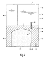
- the pin retaining portion 39 then extends from the entrance portion 38 vertically upwards in the wall block towards the top surface 2 a distance approximately corresponding to half the length of a pin. Between the inner end of the pin retaining portion 39 and the top surface 2 of the wall block 1 there is a cover 40 of block material, which is so thin that it can be penetrated by the pin 35, when striking the pin. A suitable thickness is about 3 mm, when the wall block I consists of high strength concrete.
- the entrance portion 38 is substantially wider than the pin retaining portion 39 so that it can accommodate an impact tool, i.e. a rod which is thicker than the pins 35 which shall be used as interlocking members in the retaining wall.
- the pin retaining portion 39 is substantially circular cylindrical and has the same diameter as the pins 35.
- indentations 41 i.e. longitudinal, inwardly directed indentations are provided in the pin retaining portion, said indentations being designed such that a cylindrical pin 35 made of a plastic material, which is driven in into the pin retaining portion, is retained in the aperture through friction against the projections 41, at the same time as the pressure of the pin acting against the aperture wall is not so great that the block 1 is fractured when the pin 35 is driven into the pin retaining portion 39 of the aperture 37.
- the aperture 36 in the outer corner 19 of the first recess 16 is identically designed, having an entrance portion 42 and a pin retaining portion 43.
- the modified wall block 1' which is shown in Fig. 8 and Fig. 9 is designed in the same way as the wall block 1 with the following exceptions.
- a flange or lip 50 which can be removed by a stroke with a hammer, mallet or other tool, extends, in the same way as is shown in said US-A-5,865,006, from the rear surface 5 down beyond the bottom surface 3 of block 1' at the rear of the row of pin apertures 12-15.
- the front surface 4' is arched and structured.
- the rear walls 16a' and 17a' of the recesses 16 and 17, respectively, are curved concavely between the inner and outer corners 19, 20 and 29, 30, respectively, of the recesses.
- connecting recess portions 46, 47, and 48 between said first and second recesses 16 and 17 in order further to reduce the total mass of the wall block 1'.
- These connecting recesses 46, 47, and 48 are preferably not as deep as the recesses 16 and 17 in order not to jeopardize the strength of the wall block 1'.
- the portion 25 between said first and second recesses 16, 17 is referred to as the partition wall of the block, the portion between the first recess 16 and the first end surface 6 is referred to as the left hand outer wall 26 of the block, and the portion 27 between the second recess 17 and the second end surface 7 is referred to as the right hand outer wall 27 of the block.
- the partition wall 25 is thicker than the two outer walls 26 and 27.
- the portion between the recesses 16, 17 and the rear surface 5 is referred to as the rear wall 28 of the block.
- the pin apertures 12-15 are provided in the rear wall 28.
- the pins 35 are driven into the pin retaining portions 39, 43 by means of an impact rod and a mallet so that the cover 40 is hit away and so that the pin is driven out on the other side beyond the top surface 2 of the wall block, a distance approximately corresponding to half the length of the pin 35 at the same time as the impact rod contacts the inner end of the entrance portion 38 or 42, respectively, of the aperture 36 or 37.
- the pins 35 are retained in the apertures by means of the inwardly directed projections/constrictions 41, Fig. 1A, in the pin retaining portions, so that the wall blocks can be turned upside-up, without risk that the pins will fall out.
- the wall blocks 1 are laid side by side to form a tier of wall blocks.
- FIG. 3 shows a section of a retaining wall with a lower tier of wall blocks consisting of two wall blocks designated 1a and 1b laid side by side to form a straight section of a wall. On top of these lower wall blocks 1a and 1b there is laid an upper wall block I c which shall form part of the top tier of wall blocks of the retaining wall.
- the two lower blocks 1a and 1b are laid so that they touch one another, as is shown in Fig. 3, the rear surfaces 5 being parallel and aligned.
- the upper block 1c which shall form part of the top tier of the retaining wall, is laid symmetrically on top of the two lower blocks 1a and 1b with the rear surface 5 in plane with the rear surfaces 5 of the lower blocks 1 a and 1b.
- the pins which are identified with an x, which are projecting upwards into the recesses 16 and 17 in the top block 1c will lie flush against the walls 16a and 17a, respectively, in said top block 1c in the region of the concaveness' 23 and 33 of said walls 16a and 17a of the top block 1c.
- the pins 35 will prevent the top block 1c from being pushed forwards by the masses of earth (not shown) that shall fill up the space at the rear of the wall against the rear surfaces 5 of the wall blocks.
- any pins 35 have not been driven into the pin apertures 36 and 37 of the wall blocks 1c in the top tier of wall blocks.
- the top wall block I c is resting with its outer walls 26 and 27 and rear wall 28 steadily on the top surface 2 of the lower wall blocks 1a and 1b.
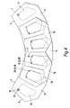
- the wall portion in Fig. 4 which has a convex curved configuration consists of three lower wall blocks 1d, 1e, and 1f, and two top wall blocks I g and 1h resting on the lower wall blocks 1d and 1e and on the lower wall blocks 1e and 1f, respectively.
- adjacent wall blocks lie with their end surfaces 6 and 7 flush against one ieanother, such as the second end surface 7 of wall block I g is lying flush against the first end side 6 of wall block 1h.
- the shadowed pin 35 which is secured in the aperture in the outer corner 29 of the second recess 17 of the lower block 1d projects upwards in the inner corner 20 of the first recess 16 of the top block 1g.
- a pin 35 in the aperture in the first recess 16 of the lower block 1e projects upwards in the inner corner 30 of the second recess 17 of the same top block 1g to safely interlock with the top block 1g.
- the right hand top block 1h is anchored in the same way to the lower blocks 1e and 1f.
- Fig. 5 shows a wall portion having a concave curved configuration, where three lower wall blocks 1d, 1e, and 1 f are laid edge to edge, partly covered by two top wall blocks 1g and 1h.
- a pin 35 which is provided in a pin aperture in an outer corner of a second recess 17 of the lower block 1d, projects upwards in the outer corner 19 of the first recess 16 of the top block 1g.
- a pin 35 which is provided in the outer corner 19 of the first recess 16 of the lower block 1e, is projecting upwards in the outer corner 29 of the second recess 17 of the top block 1g, so that the block 1g is retained by the two projecting pins 35 in the corners 19 and 29 of the first and second recesses of the upper block 1g.
- the right hand top wall block 1h is anchored in an analogous way by means of pins which project upwards from the lower blocks 1e and 1f.
- Fig. 4 and Fig. 5 illustrate two extreme cases. Also less convex or concavely curved, vertical wall are possible to construct by means of the wall blocks according to the invention.
- the pins 35 which project upwards from under lying wall blocks will lie flush against any of the straight portions 21, 22 and 31, 32, respectively, of the rear walls 16a and 17a, respectively, of the recesses. This will cause a slight displacement of the wall blocks in the cross direction of the wall. This can be completely eliminated if concave curved rear walls are used, such as the walls 16a' and 17a' according to the modified embodiment which is shown in Fig. 8.
- the wall blocks in other respects in principle are laid in the same mode as has been described with reference to the foregoing embodiment.
- the rear flange 50 first is knocked away when constructing vertical walls according to the invention.
- the interlocking pins consist of circular cylindrical plastic rods. It should be understood that also other shapes and materials are conceivable, such as for example is disclosed in said US-A-5,865,006. If, for example, the pins are corrugated, the longitudinal projections 41 can be eliminated in the pin retaining portions 43 and 39, respectively, of the apertures 36, 37.
- the embodiments according to Fig. 1-Fig. 9 combine the possibility of easily constructing a retaining wall with the advantage of the possibility to employ the same type of wall blocks also for the top tier of wall blocks for the achievement of a retaining wall with smooth surfaces on the top face without defects.
- a condition for the use of such wall blocks is that the pins are knocked into the pin apertures from underneath. Therefore the blocks must be turned a couple of times by the constructions worker, which can be felt cumbersome.
- It is a purpose of the embodiment according to Fig. 10-Fig. 12 to eliminate that inconvenience, but at the same time maintain the substantial advantages of the invention, namely the possibility to construct stabile retaining walls, straight and curved, as well as sloping walls.
- the wall block 1 depicted in Fig. 10-12 has the same external and internal shape and the same relative dimensions as the wall blocks which are shown in Fig. 1-Fig. 7.
- the general shape of the wall block therefore shall not be described here. Instead, reference is made to the above description of the first embodiments.
- Fig. 10-12 also the same reference numerals have been used as above for corresponding details.
- a pair of first pin apertures 39' and 43' extend from the top surface 2 of the block downwards into the block approximately half way to the respective recess 16 and 17. More particularly, the pin apertures 39' and 43' are provided such that their centre lines C extend through the regions of the rear outer corners 29 and 19, respectively. Possibly, the apertures 39' and 43' can be located a little more rearwards towards the rear surface 5 in order to provide a slight but sometimes desired rearward sloping of the wall, however not further rearwards than a distance from said corners corresponding to the size of the diameter of an aperture.
- the location of the apertures 39' and 43' in other words is the same as according to Fig. 1 and Fig. 2, but the apertures extend from the upper surface and downwards instead from underneath and upwards.
- the pin apertures 39' and 43' are cylindrical or possibly slightly conical, such that they are tapered downwards, so that each aperture can accommodate a retaining pin 35 which extends upwards from the top surface 2 in the same mode as according to the previous embodiment.
- a retaining wall can be constructed in the same mode as is shown in Fig. 3-7.
- the top tier can be made of blocks without pin apertures but having in other respects the same design as any of the blocks according to the present embodiment of the invention or of blocks according to Fig. 1 and Fig. 2.
- the apertures in the upper surface of the blocks of the top tier can be filled up for the achievement of a smooth top surface.
- the retaining wall can be caused to slope slightly inwards.
- the apertures 12' and 15' which are provided more rearwards, are intended to accommodate retaining pins of the same kind as the retaining pins 35 when a retaining wall shall be constructed which slopes more heavily.
- the centre line D of these second apertures 12' and 15' also extend from the top surface 2 of the block but more rearwards in the block and down into the rear wall 28 between the rear surface 5 of the block and said recess 16 and 17, respectively.
- the pins accommodated in the apertures 12' and 15' are intended to lie flush against the rear walls 16a and 17a in the recesses 16 and 17 in blocks resting above.
Landscapes
- Engineering & Computer Science (AREA)
- Civil Engineering (AREA)
- Life Sciences & Earth Sciences (AREA)
- General Life Sciences & Earth Sciences (AREA)
- Mining & Mineral Resources (AREA)
- Paleontology (AREA)
- Environmental & Geological Engineering (AREA)
- General Engineering & Computer Science (AREA)
- Structural Engineering (AREA)
- Road Paving Structures (AREA)
- Finishing Walls (AREA)
- Revetment (AREA)
- Retaining Walls (AREA)
- Cultivation Receptacles Or Flower-Pots, Or Pots For Seedlings (AREA)
Claims (19)
- Wandstein für eine Stützmauer, umfassend:a) eine vordere Oberfläche (4) und eine hintere Oberfläche (5);b) eine obere Oberfläche (2) und eine untere Oberfläche (3), die durch eine Entfernung voneinander beabstandet sind, welche die Dicke des Steins (1) definiert; undc) erste und zweite Endoberflächen (6, 7),
dadurch gekennzeichnet, dassd) mindestens eine Vertiefung (16, 17) in dem Stein (1) bereitgestellt ist, die sich von der unteren Oberfläche (3) nach oben in den Stein hinein erstreckt,e) dass die Vertiefung eine hintere Wand (16a, 17a), ein Vertiefungsdach (17e), eine äußere Seitenwand (16b, 17b) und eine innere Seitenwand (16c, 17c) aufweist, undf) dass sich mindestens ein Stiftloch (39, 39', 43, 43') in einem rechten Winkel in Bezug auf die obere Oberfläche des Steins in den Stein hinein erstreckt, wobei das Stiftloch so angeordnet ist, dass sich seine Mittellinie (C) durch den Bereich einer hinteren äußeren Ecke (19, 29) der Vertiefung erstreckt. - Wandstein gemäß Anspruch 1, dadurch gekennzeichnet, dass die hintere Wand der Vertiefung sich zwischen der hinteren äußeren Ecke und einer hinteren inneren Ecke erstreckt, wobei die hintere äußere Ecke eine Ecke zwischen der hinteren Wand und der äußeren Seitenwand definiert, und die hintere innere Ecke eine Ecke zwischen der hinteren Wand und der inneren Seitenwand ist.
- Wandstein gemäß Anspruch 2, dadurch gekennzeichnet, dass die hintere Wand der Vertiefung zwischen der äußeren und inneren Ecke konkav gekrümmt ist.
- Wandstein gemäß Anspruch 2, dadurch gekennzeichnet, dass die hintere Wand zwischen den Ecken eine Konkavität (33, 23) aufweist.
- Wandstein gemäß irgendeinem der Ansprüche 1 bis 4, dadurch gekennzeichnet, dass sich die mindestens eine Stiftöffnung (39', 43') von der oberen Oberfläche (2) des Steins eine Strecke nach unten in den Stein hinein erstreckt.
- Wandstein gemäß irgendeinem der Ansprüche 1 bis 5, dadurch gekennzeichnet, dass ebenso mindestens zwei Stiftöffnungen (12', 15') an dem hinteren Ende der ersten erwähnten Stiftöffnungen (39', 43') bereitgestellt sind, und das die zweiten Stiftöffnungen sich ebenso von der oberen Oberfläche (2) des Steins, aber weiter hinten in dem Stein, nach unten in eine hintere Wand (28) zwischen der hinteren Oberfläche (5) und der Vertiefung (16, 17) des Steins hinein erstrecken.
- Wandstein gemäß irgendeinem der Ansprüche 1 bis 4, dadurch gekennzeichnet, dass mindestens eine Stiftöffnung (36, 37) sich von einem Öffnungseingang in der Vertiefung nahe der hinteren Vertiefungswand (16a, 17a) nach oben, aber nicht den ganzen Weg bis zu der oberen Oberfläche (2) des Steins in den Stein hinein erstreckt, dass die Stiftöffnungen mindestens einen vertikalen Stifthalteabschnitt (39, 43) aufweisen, der bereitgestellt ist, um einen Stift (35) unterbringen und halten zu können, der durch den Öffnungseingang in die Öffnung getrieben wird, und dass zwischen dem inneren Ende der Stiftöffnung und der oberen Oberfläche (2) des Steins eine Abdeckung (40) von Steinmaterial verbleibt, wobei diese Abdeckung so dünn bereitgestellt ist, dass sie von einem Stift durch Schlagen des Stifts durchdrungen werden kann.
- Wandstein gemäß irgendeinem der Ansprüche 1 bis 7, dadurch gekennzeichnet, dass mindestens 2 Vertiefungen (16, 17) in dem Stein (1), eine auf jeder Seite einer vertikalen Symmetrieebene (S) durch den Stein, bereitgestellt sind, wobei sich die Vertiefungen von unterhalb in den Stein hinein erstrecken, dass jede der zwei Vertiefungen eine hintere Wand (16a, 17a) aufweist, welche die innere Oberfläche einer gemeinsamen hinteren Wand (28) des Steins ist, und eine äußere Wand (16b, 17b), welche eine innere Oberfläche von zwei äußeren Wänden (26, 27) des Steins ist, dass sich zwischen den zwei Vertiefungen eine Trennwand (25) befindet, und dass die unteren Oberflächen der hinteren Wand (28), der äußeren Wände (26, 27), und der Trennwand (25) miteinander ausgerichtet sind.
- Wandstein gemäß Anspruch 8, dadurch gekennzeichnet, dass sich in dem Bereich jeder Vertiefung eine Stiftöffnung befindet, die sich von einem Öffnungseingang in der Vertiefung nahe der hinteren Vertiefungswand nach oben, aber nicht den ganzen Weg bis zu der oberen Oberfläche des Steins in den Stein hinein erstreckt, dass die Stiftöffnung mindestens einen vertikalen Stifthalteabschnitt (39, 43) aufweist, der bereitgestellt ist, um einen Stift (35) unterbringen und halten zu können, der durch den Öffnungseingang in die Öffnung getrieben wird, und dass zwischen dem inneren Ende der Stiftöffnung und der oberen Oberfläche (2) des Steins dort eine Abdeckung (40) von Steinmaterial verbleibt, wobei diese Abdeckung so dünn bereitgestellt ist, dass sie von dem Stift durchdrungen werden kann, wenn der Stift von einem Schlag getroffen wird.
- Wandstein gemäß Anspruch 1, dadurch gekennzeichnet, dass eine integrierte Hauptvertiefung in dem Stein (1') bereitgestellt ist, umfassend Vertiefungsabschnitte (16', 17') auf jeder Seite einer vertikalen Symmetrieebene (S) durch den Stein, wobei sich die Vertiefung und der Vertiefungsabschnitt von der Unterseite nach oben in den Stein erstrecken.
- Wandstein gemäß irgendeinem der Ansprüche 7 bis 10, dadurch gekennzeichnet, dass die Abdeckung (40) eine Dicke von 2-7 mm, bevorzugt nicht mehr als 5 mm, geeigneterweise nicht mehr als 4 mm aufweist, wenn der Stein aus Gußbeton besteht.
- Wandstein gemäß irgendeinem der Ansprüche 1 bis 11, dadurch gekennzeichnet, dass die hintere Vertiefungswand bzw. die hinteren Vertiefungswände (16a, 17a) vertikal ist/sind.
- Wandstein gemäß irgendeinem der Ansprüche 7 bis 12, dadurch gekennzeichnet, dass die Stiftöffnung(en) in einer hinteren Ecke (19, 29) der Vertiefung (16, 17) bereitgestellt ist/sind.
- Wandstein gemäß irgendeinem der Ansprüche 7 bis 13, dadurch gekennzeichnet, dass die Stiftöffnung einen Stifthalteabschnitt (39, 43) und einen breiteren Eingangsabschnitt (38, 42) für ein Werkzeug zum Vortreiben des Stifts in den Stifthalteabschnitt der Öffnung und durch die Abdeckung aufweist.
- Wandstein gemäß irgendeinem der vorhergehenden Ansprüche, dadurch gekennzeichnet, dass ebenso eine Anzahl von Stiftöffnungen (12-15) in einer hinteren Wand (28) zwischen der hinteren Oberfläche (5) und der Vertiefung/den Vertiefungen (16, 17) des Steins bereitgestellt ist, die sich von der unteren Oberfläche (3) des Steins eine Strecke vertikal nach oben in die hintere Wand hinein erstrecken.
- Stützmauer, bestehend aus Wandsteinen (1), die gelegt sind, um Lagen von Wandsteinen aufeinander zu bilden, so dass die Steine in jeder Lage in der seitlichen Richtung in Bezug auf die Steine in oberhalb liegenden und unterhalb liegenden Lagen um eine Strecke versetzt sind, die der halben Länge eines Steins entspricht, wobei die Wandsteine umfassen:a) eine vordere Oberfläche (4) und eine hintere Oberfläche (5);b) eine obere Oberfläche (2) und eine untere Oberfläche (3), die durch eine Entfernung voneinander beabstandet sind, welche die Dicke des Steins (1) definiert; undc) erste und zweite Endoberflächen (6, 7),
dadurch gekennzeichnet, dassd) mindestens eine Vertiefung (16, 17) in dem Stein (1) bereitgestellt ist, die sich von der unteren Oberfläche (3) nach oben in den Stein hinein erstreckt,e) dass die Vertiefung eine hintere Wand (16a, 17a), ein Vertiefungsdach (17e), eine äußere Seitenwand (16b, 17b) und eine innere Seitenwand (16c, 17c) aufweist,f) dass sich mindestens ein Stiftloch (39, 39', 43, 43') in einem rechten Winkel in Bezug auf die obere Oberfläche des Steins in den Stein hinein erstreckt, wobei das Stiftloch so angeordnet ist, dass sich seine Mittellinie (C) durch den Bereich einer hinteren äußeren Ecke (19, 29) der Vertiefung erstreckt, undg) dass in allen den Lagen, die aus Wandsteinen bestehen, außer in den Steinen in der oberen Lage, ein Stift in die Öffnung eingesetzt ist, wobei sich ein vorragender Teil des Stifts über die obere Oberfläche (2) des Wandsteins hinaus erstreckt, wobei der vorragende Stiftteil bündig gegen die hintere Wand eines Wandsteins in einer oberhalb liegenden Lage von Wandsteinen anliegt. - Stützmauer gemäß Anspruch 16, dadurch gekennzeichnet, dass sich mindestens eine Stiftöffnung (39', 43') von der oberen Oberfläche (2) des Steins eine Strecke nach unten in den Stein hinein erstreckt, und dass diese Stifte von oberhalb nach unten in die Stiftöffnungen eingesetzt sind.
- Stützmauer gemäß Anspruch 16, dadurch gekennzeichnet,a) dass sich in mindestens allen Lagen von Wandsteinen unterhalb der oberen Lage mindestens eine Stiftöffnung (36, 37) von einem Öffnungseingang in der Vertiefung nahe der hinteren Vertiefungswand (16a, 17a) nach oben, aber nicht den ganzen Weg bis zu der oberen Oberfläche (2) des Steins in den Stein hinein erstreckt,b) dass die Stiftöffnung mindestens einen vertikalen Stifthalteabschnitt (39, 43) aufweist, der bereitgestellt ist, um einen Verriegelungsstift (35) unterbringen und halten zu können, der durch den Öffnungseingang in die Öffnung getrieben wird,c) dass in allen Lagen von Wandsteinen, außer in den Steinen der oberen Lage, ein Stift (35) von unterhalb in die Stiftöffnungen und über die obere Oberfläche des Wandsteins hinaus getrieben ist, der eine Abdeckung (40) zwischen dem inneren Ende der Öffnung und der oberen Oberfläche des Steins durchdringt, wobei der vorragende Stiftabschnitt bündig gegen die hintere Wand einer Vertiefung eines Wandsteins in einer oberhalb liegenden Lage von Wandsteinen anliegt, undd) dass in den Wandsteinen der oberen Lage von Wandsteinen kein Stift in die Stiftöffnungen getrieben ist, der die Abdeckung (40) durchdringt, so dass die Abdeckung und somit die obere Oberfläche der Wandsteine der oberen Lage von Wandsteinen intakt ist.
- Stützmauer gemäß irgendeinem der Ansprüche 16 bis 18, dadurch gekennzeichnet, dass mindestens 2 Vertiefungen (16, 17) in den Steinen (1), eine auf jeder Seite einer vertikalen Symmetrieebene (S) durch die Steine, bereitgestellt sind, wobei sich die Vertiefungen von der unteren Oberfläche nach oben in die Steine hinein erstrecken, dass jede der zwei Vertiefungen in den Steinen eine hintere Wand (16a, 17a) aufweist, welche die Innenseite einer gemeinsamen hinteren Wand (28) des Steins ist, und eine äußere Wand (16b, 17b), welche die Innenseite eines Paars äußerer Wänden (26, 27) des Steins ist, dass sich zwischen den zwei Vertiefungen eine Trennwand (25) befindet, dass die unteren Oberflächen der hinteren Wand (28), der äußeren Wand (26, 27), und der Trennwand (25) miteinander ausgerichtet sind, und dass mindestens eine äußere Wand (26, 27) des Steins in jeder Lage von Steinen, außer der unteren Lage, mindestens teilweise gegen die Trennwand (25) des Steins einer unterhalb liegenden Lage anliegt.
Priority Applications (1)
| Application Number | Priority Date | Filing Date | Title |
|---|---|---|---|
| DK00957175T DK1206602T3 (da) | 1999-08-27 | 2000-08-17 | Murblok og stöttemur lavet af sådanne blokke |
Applications Claiming Priority (5)
| Application Number | Priority Date | Filing Date | Title |
|---|---|---|---|
| SE9903048 | 1999-08-27 | ||
| SE9903048A SE514759C2 (sv) | 1999-08-27 | 1999-08-27 | Murblock samt stödmur av sådana murblock |
| SE0001046A SE0001046D0 (sv) | 2000-03-23 | 2000-03-23 | Murblock samt stödmur av sådana murblock (II) |
| SE0001046 | 2000-03-23 | ||
| PCT/SE2000/001586 WO2001016432A1 (en) | 1999-08-27 | 2000-08-17 | Wall block and retaining wall made of such blocks |
Publications (2)
| Publication Number | Publication Date |
|---|---|
| EP1206602A1 EP1206602A1 (de) | 2002-05-22 |
| EP1206602B1 true EP1206602B1 (de) | 2004-10-13 |
Family
ID=26655037
Family Applications (1)
| Application Number | Title | Priority Date | Filing Date |
|---|---|---|---|
| EP00957175A Expired - Lifetime EP1206602B1 (de) | 1999-08-27 | 2000-08-17 | Mauerstein und mit solchem stein hergestellte stützmauer |
Country Status (7)
| Country | Link |
|---|---|
| EP (1) | EP1206602B1 (de) |
| AT (1) | ATE279592T1 (de) |
| AU (1) | AU6882900A (de) |
| DE (1) | DE60014929D1 (de) |
| DK (1) | DK1206602T3 (de) |
| NO (1) | NO321238B1 (de) |
| WO (1) | WO2001016432A1 (de) |
Family Cites Families (4)
| Publication number | Priority date | Publication date | Assignee | Title |
|---|---|---|---|---|
| US4825619A (en) * | 1986-09-15 | 1989-05-02 | Keystone Retaining Wall Systems, Inc. | Block wall |
| US5294216A (en) * | 1989-09-28 | 1994-03-15 | Anchor Wall Systems, Inc. | Composite masonry block |
| US5252017A (en) * | 1991-01-30 | 1993-10-12 | Wedgerock Corporation | Setback retaining wall and concrete block and offset pin therefor |
| US5865006A (en) * | 1997-06-02 | 1999-02-02 | Keystone Retaining Wall Systems, Inc. | Retaining wall block and wall construction |
-
2000
- 2000-08-17 EP EP00957175A patent/EP1206602B1/de not_active Expired - Lifetime
- 2000-08-17 AT AT00957175T patent/ATE279592T1/de not_active IP Right Cessation
- 2000-08-17 DK DK00957175T patent/DK1206602T3/da active
- 2000-08-17 DE DE2000614929 patent/DE60014929D1/de not_active Expired - Lifetime
- 2000-08-17 WO PCT/SE2000/001586 patent/WO2001016432A1/en not_active Ceased
- 2000-08-17 AU AU68829/00A patent/AU6882900A/en not_active Abandoned
-
2002
- 2002-02-26 NO NO20020934A patent/NO321238B1/no not_active IP Right Cessation
Also Published As
| Publication number | Publication date |
|---|---|
| ATE279592T1 (de) | 2004-10-15 |
| WO2001016432A1 (en) | 2001-03-08 |
| DE60014929D1 (de) | 2004-11-18 |
| AU6882900A (en) | 2001-03-26 |
| EP1206602A1 (de) | 2002-05-22 |
| NO20020934L (no) | 2002-02-26 |
| DK1206602T3 (da) | 2005-01-31 |
| NO321238B1 (no) | 2006-04-10 |
| NO20020934D0 (no) | 2002-02-26 |
Similar Documents
| Publication | Publication Date | Title |
|---|---|---|
| US7244079B1 (en) | Retaining wall system | |
| US5653558A (en) | Retaining wall block | |
| US6622445B1 (en) | Modular wall block with mechanical anchor pin | |
| US4512685A (en) | Mortarless retaining-wall system and components thereof | |
| US5505034A (en) | Retaining wall block | |
| US6652197B2 (en) | Interlocking segmental retaining wall | |
| EP0232050B1 (de) | Stützmauersystem | |
| US7351014B2 (en) | Block with multifaceted bottom surface | |
| US7096634B2 (en) | Block wall system | |
| US6168353B1 (en) | Retaining wall and method of wall construction | |
| US20040159065A1 (en) | Retaining wall block | |
| CA2258637A1 (en) | Block for retaining wall and method for the construction of retaining wall using the same | |
| AU624824B2 (en) | Facing system | |
| EP1206602B1 (de) | Mauerstein und mit solchem stein hergestellte stützmauer | |
| US4930283A (en) | Brick | |
| CN108487264B (zh) | 一种护坡砖及挡土墙垒砌方法 | |
| KR200238747Y1 (ko) | 보강토 옹벽 축조용 앵커 블록 | |
| US20080244995A1 (en) | Wall Assembly | |
| US20090110491A1 (en) | Securable retaining wall block and system | |
| KR100878716B1 (ko) | 연결식 축조식생블록 | |
| EP0544953A1 (de) | Verfahren und Vorrichtung zum Befestigen von Bauteilen oder anderen Artikeln an einer tragenden Konstruktion | |
| US20060096180A1 (en) | Retaining wall block and grid system | |
| EP0733741B1 (de) | Böschungsstein für eine Schützmauer und ein Schützbauwerk | |
| AU782613B2 (en) | Retaining wall block | |
| KR200172438Y1 (ko) | 블록식 보강토 옹벽축조용 앵커블록 |
Legal Events
| Date | Code | Title | Description |
|---|---|---|---|
| PUAI | Public reference made under article 153(3) epc to a published international application that has entered the european phase |
Free format text: ORIGINAL CODE: 0009012 |
|
| 17P | Request for examination filed |
Effective date: 20020117 |
|
| AX | Request for extension of the european patent |
Free format text: AL;LT;LV;MK;RO;SI |
|
| GRAP | Despatch of communication of intention to grant a patent |
Free format text: ORIGINAL CODE: EPIDOSNIGR1 |
|
| GRAP | Despatch of communication of intention to grant a patent |
Free format text: ORIGINAL CODE: EPIDOSNIGR1 |
|
| GRAS | Grant fee paid |
Free format text: ORIGINAL CODE: EPIDOSNIGR3 |
|
| GRAA | (expected) grant |
Free format text: ORIGINAL CODE: 0009210 |
|
| AK | Designated contracting states |
Kind code of ref document: B1 Designated state(s): AT BE CH CY DE DK ES FI FR GB GR IE IT LI LU MC NL PT SE |
|
| PG25 | Lapsed in a contracting state [announced via postgrant information from national office to epo] |
Ref country code: LI Free format text: LAPSE BECAUSE OF FAILURE TO SUBMIT A TRANSLATION OF THE DESCRIPTION OR TO PAY THE FEE WITHIN THE PRESCRIBED TIME-LIMIT Effective date: 20041013 Ref country code: FR Free format text: LAPSE BECAUSE OF FAILURE TO SUBMIT A TRANSLATION OF THE DESCRIPTION OR TO PAY THE FEE WITHIN THE PRESCRIBED TIME-LIMIT Effective date: 20041013 Ref country code: CH Free format text: LAPSE BECAUSE OF FAILURE TO SUBMIT A TRANSLATION OF THE DESCRIPTION OR TO PAY THE FEE WITHIN THE PRESCRIBED TIME-LIMIT Effective date: 20041013 Ref country code: AT Free format text: LAPSE BECAUSE OF FAILURE TO SUBMIT A TRANSLATION OF THE DESCRIPTION OR TO PAY THE FEE WITHIN THE PRESCRIBED TIME-LIMIT Effective date: 20041013 Ref country code: BE Free format text: LAPSE BECAUSE OF FAILURE TO SUBMIT A TRANSLATION OF THE DESCRIPTION OR TO PAY THE FEE WITHIN THE PRESCRIBED TIME-LIMIT Effective date: 20041013 Ref country code: NL Free format text: LAPSE BECAUSE OF FAILURE TO SUBMIT A TRANSLATION OF THE DESCRIPTION OR TO PAY THE FEE WITHIN THE PRESCRIBED TIME-LIMIT Effective date: 20041013 Ref country code: IT Free format text: LAPSE BECAUSE OF FAILURE TO SUBMIT A TRANSLATION OF THE DESCRIPTION OR TO PAY THE FEE WITHIN THE PRESCRIBED TIME-LIMIT;WARNING: LAPSES OF ITALIAN PATENTS WITH EFFECTIVE DATE BEFORE 2007 MAY HAVE OCCURRED AT ANY TIME BEFORE 2007. THE CORRECT EFFECTIVE DATE MAY BE DIFFERENT FROM THE ONE RECORDED. Effective date: 20041013 |
|
| REG | Reference to a national code |
Ref country code: GB Ref legal event code: FG4D |
|
| REG | Reference to a national code |
Ref country code: CH Ref legal event code: EP |
|
| REG | Reference to a national code |
Ref country code: IE Ref legal event code: FG4D |
|
| REF | Corresponds to: |
Ref document number: 60014929 Country of ref document: DE Date of ref document: 20041118 Kind code of ref document: P |
|
| PG25 | Lapsed in a contracting state [announced via postgrant information from national office to epo] |
Ref country code: GR Free format text: LAPSE BECAUSE OF FAILURE TO SUBMIT A TRANSLATION OF THE DESCRIPTION OR TO PAY THE FEE WITHIN THE PRESCRIBED TIME-LIMIT Effective date: 20050113 |
|
| PG25 | Lapsed in a contracting state [announced via postgrant information from national office to epo] |
Ref country code: DE Free format text: LAPSE BECAUSE OF FAILURE TO SUBMIT A TRANSLATION OF THE DESCRIPTION OR TO PAY THE FEE WITHIN THE PRESCRIBED TIME-LIMIT Effective date: 20050114 |
|
| PG25 | Lapsed in a contracting state [announced via postgrant information from national office to epo] |
Ref country code: ES Free format text: LAPSE BECAUSE OF FAILURE TO SUBMIT A TRANSLATION OF THE DESCRIPTION OR TO PAY THE FEE WITHIN THE PRESCRIBED TIME-LIMIT Effective date: 20050124 |
|
| REG | Reference to a national code |
Ref country code: DK Ref legal event code: T3 |
|
| REG | Reference to a national code |
Ref country code: SE Ref legal event code: TRGR |
|
| LTIE | Lt: invalidation of european patent or patent extension |
Effective date: 20041013 |
|
| NLV1 | Nl: lapsed or annulled due to failure to fulfill the requirements of art. 29p and 29m of the patents act | ||
| REG | Reference to a national code |
Ref country code: CH Ref legal event code: PL |
|
| PG25 | Lapsed in a contracting state [announced via postgrant information from national office to epo] |
Ref country code: LU Free format text: LAPSE BECAUSE OF NON-PAYMENT OF DUE FEES Effective date: 20050817 Ref country code: CY Free format text: LAPSE BECAUSE OF FAILURE TO SUBMIT A TRANSLATION OF THE DESCRIPTION OR TO PAY THE FEE WITHIN THE PRESCRIBED TIME-LIMIT Effective date: 20050817 Ref country code: IE Free format text: LAPSE BECAUSE OF NON-PAYMENT OF DUE FEES Effective date: 20050817 |
|
| PLBE | No opposition filed within time limit |
Free format text: ORIGINAL CODE: 0009261 |
|
| STAA | Information on the status of an ep patent application or granted ep patent |
Free format text: STATUS: NO OPPOSITION FILED WITHIN TIME LIMIT |
|
| PG25 | Lapsed in a contracting state [announced via postgrant information from national office to epo] |
Ref country code: MC Free format text: LAPSE BECAUSE OF NON-PAYMENT OF DUE FEES Effective date: 20050831 |
|
| 26N | No opposition filed |
Effective date: 20050714 |
|
| EN | Fr: translation not filed | ||
| REG | Reference to a national code |
Ref country code: IE Ref legal event code: MM4A |
|
| PG25 | Lapsed in a contracting state [announced via postgrant information from national office to epo] |
Ref country code: PT Free format text: LAPSE BECAUSE OF NON-PAYMENT OF DUE FEES Effective date: 20050313 |
|
| PGFP | Annual fee paid to national office [announced via postgrant information from national office to epo] |
Ref country code: FI Payment date: 20130819 Year of fee payment: 14 Ref country code: DK Payment date: 20130821 Year of fee payment: 14 Ref country code: SE Payment date: 20130821 Year of fee payment: 14 |
|
| PGFP | Annual fee paid to national office [announced via postgrant information from national office to epo] |
Ref country code: GB Payment date: 20130828 Year of fee payment: 14 |
|
| REG | Reference to a national code |
Ref country code: DK Ref legal event code: EBP Effective date: 20140831 |
|
| REG | Reference to a national code |
Ref country code: SE Ref legal event code: EUG |
|
| GBPC | Gb: european patent ceased through non-payment of renewal fee |
Effective date: 20140817 |
|
| PG25 | Lapsed in a contracting state [announced via postgrant information from national office to epo] |
Ref country code: FI Free format text: LAPSE BECAUSE OF NON-PAYMENT OF DUE FEES Effective date: 20140817 |
|
| PG25 | Lapsed in a contracting state [announced via postgrant information from national office to epo] |
Ref country code: SE Free format text: LAPSE BECAUSE OF NON-PAYMENT OF DUE FEES Effective date: 20140818 |
|
| PG25 | Lapsed in a contracting state [announced via postgrant information from national office to epo] |
Ref country code: DK Free format text: LAPSE BECAUSE OF NON-PAYMENT OF DUE FEES Effective date: 20140831 Ref country code: GB Free format text: LAPSE BECAUSE OF NON-PAYMENT OF DUE FEES Effective date: 20140817 |